charging system HONDA CIVIC 2002 7.G Owner's Manual
[x] Cancel search | Manufacturer: HONDA, Model Year: 2002, Model line: CIVIC, Model: HONDA CIVIC 2002 7.GPages: 1139, PDF Size: 28.19 MB
Page 827 of 1139
Heating and Air Conditioning
Refrigerant Leak Test
Special Tool Required
Leak detector, Honda Tool and Equipment YGK-H-10PM
commerciallv available
Compressed air mixed with R-134a forms a
combustible vapor.
The vapor can burn or explode causing serious
injury.
Never use compressed air to pressure test
R-134a service equipment or vehicle air
conditioning system.
Air conditioning refrigerant or lubricant vapor
can irritate your eyes, nose, or throat.
Be carefulwhen connecting service equipment.
Do not breathe refrigerant or vapor
Use only service equipment that is U.L.-listed and is
certiified to meet the requirements of SAE J2210 to
remove HFC-134a (R-134a) from the air conditioning
system.
lf accidental system discharge occurs, ventilate the
work area before resuming service.
R-134a service equipment or vehicle air conditioning
systems should not be pressure tested or leak tested
with compressed air.
Additional health and safety information may be
obtained from the refrigerant and lubricant
manufacturers.
21-56
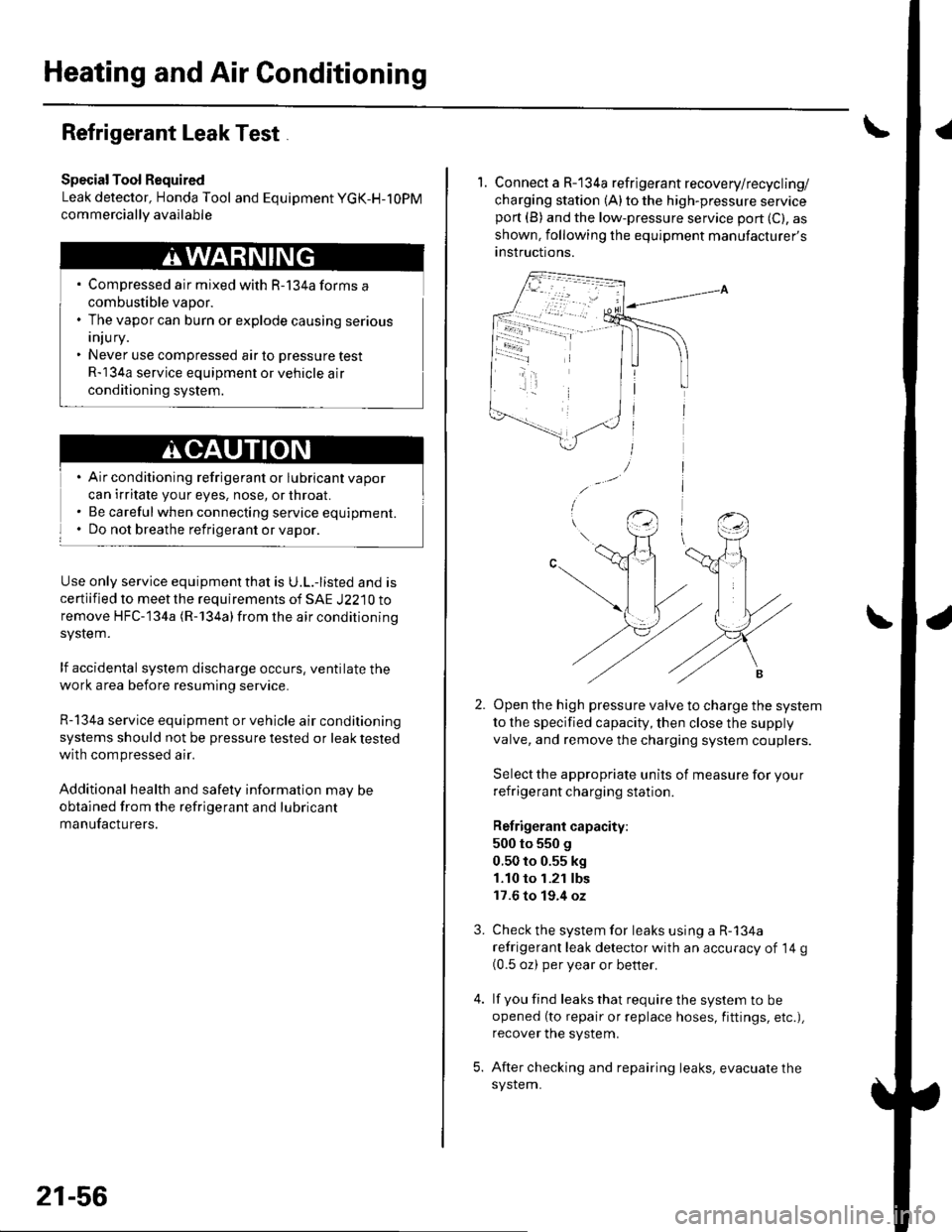
1. Connect a R-134a refrigerant recovery/recycling/
charging station (A) to the high-pressure serviceport (B) and the low-pressure service port (C), as
shown, following the equipment manufacturer's
anstructions.
Open the high pressure valve to charge the system
to the specified capacity, then close the supply
valve, and remove the charging system couplers.
Select the appropriate units of measure for your
refrigerant charging station.
Refrigerant capacity:
500 to 550 g
0.50 to 0.55 kg
1.10 to 1.21 lbs
17.6 to 19.4 oz
Check the system for leaks using a R-134a
refrigerant leak detector with an accuracy of 14 g(0.5 oz) per year or better.
lf you find leaks that require the system to be
opened (to repair or replace hoses, fittings, etc.),
recover the system.
After checking and repairing leaks, evacuate the
system.
3.
Page 829 of 1139
Heating and Air Conditioning
A/C System Tests (cont'd)
1.
Performance Test
Air conditioning refrigerant or lubricant vapor
can irritate your eyes, nose, or throar.
Be carefulwhen connecting service equipment.
Do not breathe refrigerant or vapor.
The performance test will help determine if the air
conditioner system is operating within specifications.
Use only service equipment that is U.L.-listed and is
cenified to meet the requirements of SAE J2210 toremove HFC-134a (R-134alfrom the air conditioning
system.
lf accidental system discharge occurs, ventilate the
work area before resuming service
R-134a service equipment or vehicle air conditioning
systems should not be pressure tested or leak testedwith compressed air.
Additional health and safety information may be
obtained from the refrigerant and lubricant
manufacturers.
Connect a R-134a refrigerant recover/recycling/
charging station to the high-pressure service port
and the low-pressure service port, following the
equipment manufacturer's instructions.
Determine the relative humidity and air
Iemperaru re.
' Compressed air mixed with R-134a forms a
combustible vapor.. The vapor can burn or explode causing serious
Injury.. Never use compressed air to pressure test
R-134a service equipment or vehicle air
conditioning systems.
21-58
4.
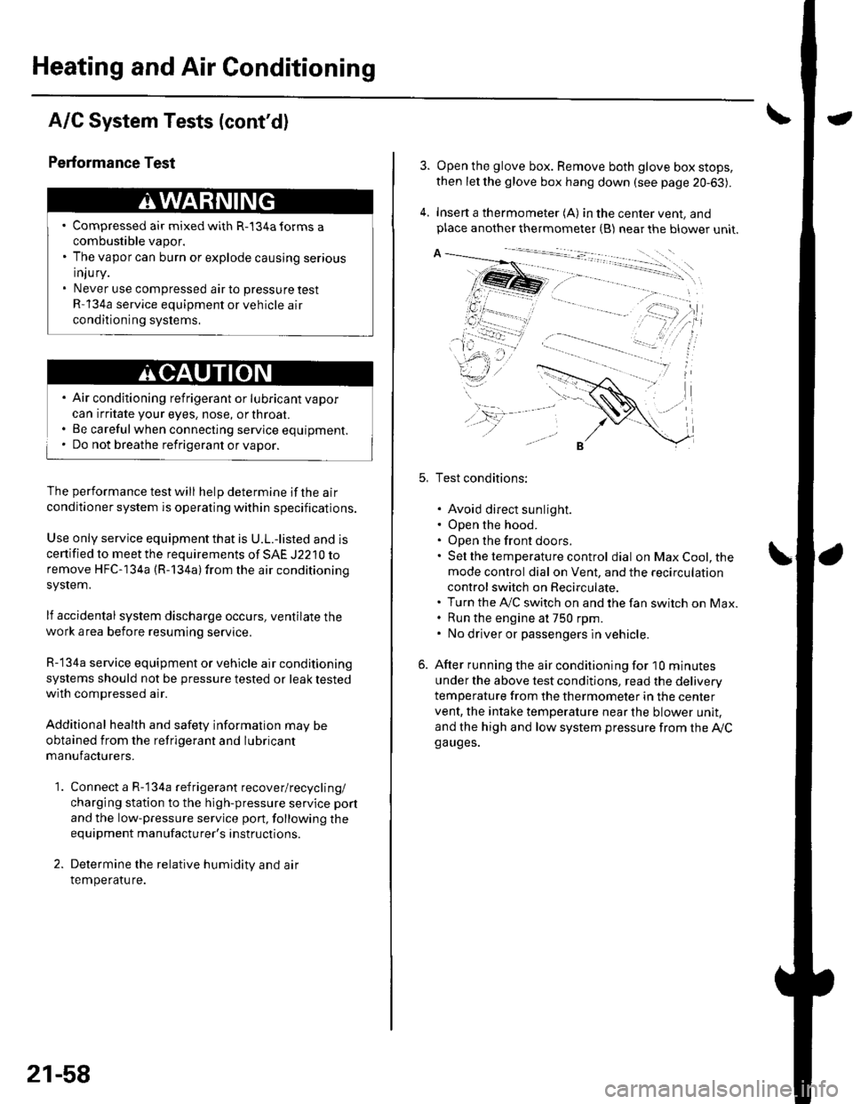
Open the glove box. Remove both glove box stops,
then let the glove box hang down (see page 20-63).
Insert a thermometer (A) in the center vent, andplace another thermometer {B) near the blower unit.
Test conditions:
. Avoid direct sunlight.. Open the hood.. Open the front doors.. Sel the temperature control dial on Max Cool, the
mode control dial on Vent, and the recirculation
control switch on Recirculate.. Turn the A,/C switch on and the fan switch on Max.. Run the engine at 750 rpm.. No driver or passengers in vehicle.
After running the air conditioning for I0 minutes
under the above test conditjons, read the delivery
temperature from the thermometer in the center
vent, the intake temperature near the blower unit,
and the high and low system pressure from the Ay'Cga uges.
Page 1036 of 1139
IJ
lr
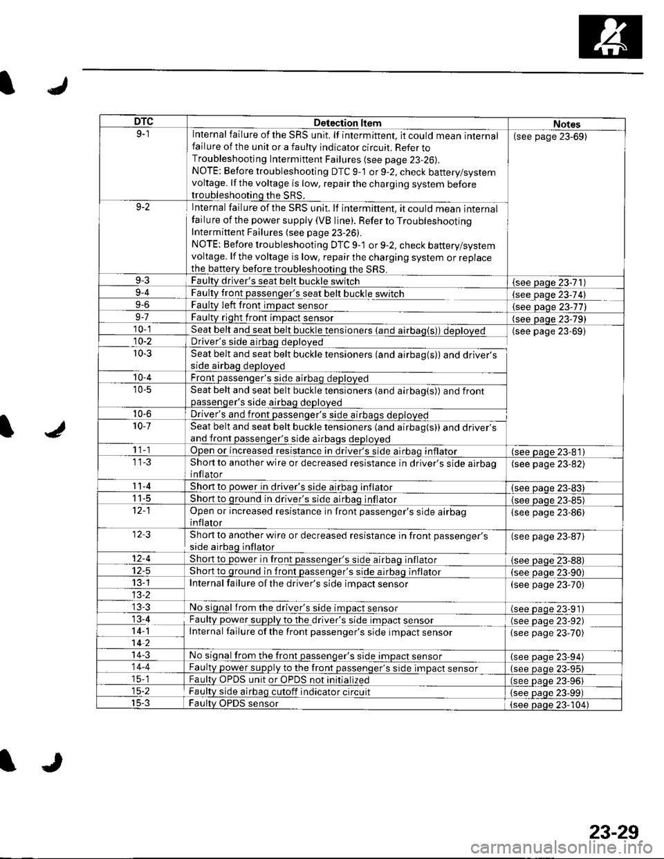
DTCDetection ltemNotes9-1Internal failure of the SRS unit. lf intermittent, it could mean internalfailure of the unit or a faulty indicator circuit. Refer toTroubleshooting Intermittent Failures (see page 23-26).
NOTE: Before troubleshooting DTC 9-1 or 9-2, check battery/systemvoltage. lf the voltage is low, repair the charging system beforetroubleshooting the SRS.
(see page 23-69)
9-2Internal failure of the SRS unit. lf intermittent, it could mean internalfailu re of the power supply (VB line). Refer to TroubleshootingIntermittent Failures (see page 23-26).
NOTE: Before troubleshooting DTC 9-1 or 9-2, check battery/systemvoltage. lf the voltage is low, repair the charging system or replacethe b€ttery before troubleshooting the SRS.
9-3Faulty driver's seat belt buckle switch(see Daqe 23-71)9-4
9-6
FaultLtglt passenger's seat belt buckle switch
Faulty Ieft front imDact sensorlgqgfage 23-74)
{see Daqe 23-77)9-7Faulty right front impact sensor(see paqe 23-79)10-1Seat belt and seat belt buckle tensioners (and airbag(s)) deployedDriver's side airbag deployed
Seat belt and seat belt buckle tensioners (and airbag(s)) and driver'sside airbag deployed
Front passenqer's side airbao deDloved
(see page 23-69)10-2
r0-3
'10-4
'10-5Seat belt and seat belt buckle tensioners (and airbag(s)) and frontpassenqer's side airbaq deDloved
10-6Driver's and front passenqer's side al10-7Seat belt and seat belt buckle tensioners (and airbag(s)) and driver'sand front passenger's side airbags deployed
1 1-1Open or increased resistance in driver's side airbao inflator(see paqe 23-81)Short to another wire or decreased resistance in driver's side airbaoinflator
(see page 23-82)
11-4Short to power in driver's side airbaq inflator(see oaqe 23-83)I t-5Short to ground in driver's side airbaq inflator{see paqe 23-85)Open or increased resistance in front passenger's side airbaginflator
(see page 23-86)
Short to another wire or decreased resistance in front passenger's
side airbag inflator
(see page 23-87)
12-4Short to power in front passenqer's side airbaq inflator{see Daqe zJ-uu}I z-5Short to ground in front passenger's side airbaq inflator(see oaqe 23-90)13-1Internal failure of the driver's side impact sensor(see page 23-70)
No signal from the driver's side impact sensor(see paqe 23-91)13-4
14-1-7ii,
Faulty power supply to the df,rglllug t Opact s9I99LInternal failure ofthe front passenger's side impact sensor
(see page 23-92)(see page 23-70)
14-3No signal from the front passenger's side impact sensor(see paqe 23-94)14-4Faulty power supply to the front passenqer's side impact sensor(see page 23-95)15-1Faultv OPDS unit or OPDS not initialized(see paqe 23-96115-2Faulty side airbag cutoff indicator circuit(see Daqe 23-99)15-3Faulty OPDS sensor(see oaoe 23-104)
IJ
23-29
Page 1076 of 1139
I
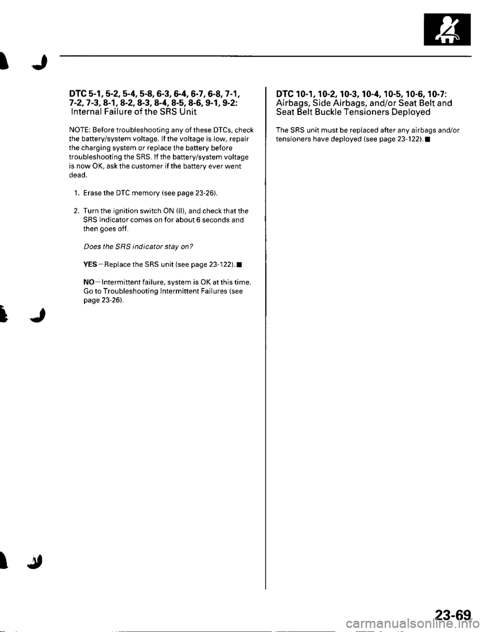
DTC s-1, 5-2, 5-4, s-8, 6-3, 6-4,6-7,6-8,7-1,
7-2,7-3, A-1,4-2, 8-3, 8-4, 8-5, 8-6, 9-1, 9-2:
Internal Failure of the SRS Unit
NOTE: Before troubleshooting any of these DTCs, check
the battery/system voltage. lf the voltage is low, repair
the charging system or replace the battery before
troubleshooting the SRS. lf the battery/system voltage
is now OK, ask the customer if the battery ever went
oeao,
1. Erase the DTC memory (see page 23-26).
2. Turn the ignition switch ON (ll), and check that the
SRS indicator comes on for about 6 seconds and
then goes off.
Does the SRS indicatot stay on?
YES Replace the SRS unit (see page 23-122).1
NO Intermittent failure, system is OK at this time.
Go to Troubleshooting lntermittent Failures (see
page 23-26).
l
I
DTC 10-1, 10-2, 10-3, 10-4, 10-s, 10-6, 10-7:
Airbags, Side Airbags, and/or Seat Belt and
Seat Belt Buckle Tensioners Deployed
The SRS unit must be replaced after any airbags and/or
tensioners have deployed (see page 23-122). !
23-69
Page 1134 of 1139
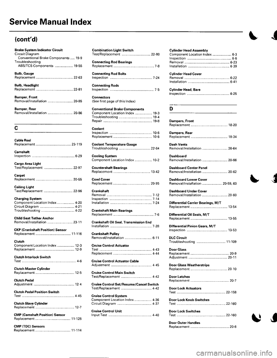
Service Manual Index
(cont'dl
Brake System Indicator CircuitCircuit DiagramConventional Brake Components..... 19-9TroubleshootingABS/TCS Components .... ....... ...... 19-55
Bulb, GeugeRep|acemenl................ .. ............2263
Bulb, HeadlightReplacement ......................................... 22-A1
Bumper, FrontRemoval/1nsra11ation ............................ 20 85
Bumper, RearRemoval/lnstallation... ... . .....20.86
Combination Light SwilchTesVReplacement ..............................22 80
Connecting Rod BearingsRep|acement...................... .......-....7-8
Connecting Rod Boltsf nspection ....................-.-.-.-.................... 7 -24
Connecting RodsInspection ........,,.,.,...,.,.,.,.,,,,.,,,.,.,.,.,.,.,.,.. 7 5
Connectors(See first page of this Index)
Conventional Brake Component3Component Location Index ................... 19'3Troub1eshootin9 ..................................... 19-4
Cylinder Head AssemblyComponent Location Index ..................... 6-3Inspection ................................................. 6 6Removal ..........&�23Insta11alion .............................................. 6 39
Cylinder Head Cover8emova1 ..............-.-................................. 6-22Installation ..............................................6-41
Cylinder Head, BareInspecton..,.....,.
D
c
Cable ReelReplacement....................................... 23-1 19
CamshaftInspection .......................-...-................... 6-29
Cargo Area LightTesVRep1acement ................................ 22-97
CarpetReplacement.....-...-..... ... ......-.20-55
Ceiling Light-estrReplacement ................................ 22.96
Charging SystemComponent Location Index................... 4-20Circuit Diagram ...................................... 4-21
19-8
CoolantInspection .................. ..... .. 106Replacement................. ... . .. 10 6
Coolant Temperature Gat|geTroub1eshootin9................................... 22 64
Cooling SyslemComponent Location Index................... 10-2
Countershaft BearingsReplacement............... ..................... 13-42
Cowl CoverReplacement............... .. ..... ....20-95
CrankshaftRemoval .................................................. 7 -12
Repair ..................
Inspec(on,,,,,........1 14
Dampers. FrontReplacement................ ..................... 18 20
Oampers, RearRep1acement......................................... 18-34
Dash VentsBemoval/lnstallation .-.......................... 20-64
DashboardBemoval/1nsta11ation ............................ 20-66
Oashboard Center PanelRemoval/1nstaf 1ation ............................ 20 62
Dashboard Lower CoverRemoval/lnstallation ...................... 20-59, 63
Dashboard Under CoverRemoval/lnstallation ............................ 20 60
Diff erential Carrier Bearings, M/TRep1acement,,......,...,...,.,.,,,.,.,,,........,.,. 13-54
Ditferential Oil Seals, M/T8ep1acement......................................... 13-55
Differential Pinion Gears, M/TInspection .,....-,.,,,.,..,.-,.,.........,.,.,,, 13 53
OLC CircuitTroubleshooting ................................ 1 1-109
Door GlassRep1acement.,.,,,,,,,,,,,.,,,,,,,,,,.,.,.,.,.,,,,,,.,, 20-9Adjustment. .. .....................20-11
Door Glass WeathelstripsReplacement .............-.. . . . ..........-......20 10
Door LatchesReplacement ..........-.-.............................. 20-7
Door Lock ActuatorsTest ...................................................... 22-154
Door Lock Knob SwitchesTest -......... . . . - . . . . . . . . ......22-160
Door Lock SwitchesTest ........... ............................ ............. 22-160
Door Outer HandlesRep1acemen1 ........................................... 20-6
3
Child Seat Tether AnchorRemoval/lnstaf lat;on .. ........................ 23 11
CKP (Crankshaft Position) SonsorReplacement....................................... 1 1-116
ClutchComponentLocation 1ndex................... 12-3Rep1acemen1........................................... 12-9
Clutch InteYlock SwitchTest.....-........-...-............. ...---.-.......4-6
Clutch Master CylinderReplacement........................................... 12 5
clutch PedalAdjustment ............................................. 12 4
Clutch Pedal Position SwitchTest.,.,,,,,.,,,.,.,,,,,,.,.,,,,,,,,,.,,,,,.. ......445
lnstallation.................. . ..... .....1-24
Crankshalt Main BearingsReplacement........-.-.................................. 7-6
CrankshaftOil Seal,Transmission End1nstanation .............................................. 7 28
Crankshafl PulleyRemoval/lnstallation -..................-.......... 6-1 1
Cruise Control Actuator
Troubleshooting
Clutch Slave CylindorBeplacemeit...
...................... 4-43
.......4-22
Test
12-1
RepIacement........................................... 4-44
Cruise Control Actuator CableAdjustment ............................................. 4 45
Cruise Control Main SwitchTesVRep1acement .................................. 4 42
Cruise Control Set/Resume/Cancel SwitchTesVRep1acement .................................. 4 42
Cruise Control SystomComponent Localion Inde\................... 4-36Circuit Diagram ....-................................. 4 37
Cruise Control UnitInputTest.............................. .. ...4,40CMP {Camshaft Positionl Senso]Replacement....-...-.............................. 1 1-128
CMP (TDC) SensorsReplacement............-.......................... 1 1 1 14