fuel pressure sensor HONDA CIVIC 2002 7.G Owner's Manual
[x] Cancel search | Manufacturer: HONDA, Model Year: 2002, Model line: CIVIC, Model: HONDA CIVIC 2002 7.GPages: 1139, PDF Size: 28.19 MB
Page 379 of 1139
EVAP System
DTC Troubleshooting (cont'd)
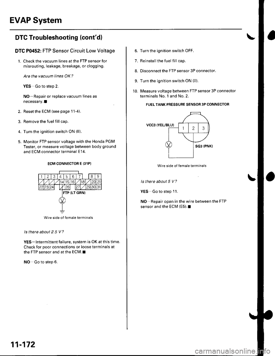
DTC P0452: FTP Sensor Circuit Low Voltage
1. Check the vacuum lines at the FTP sensor for
misrouting, leakage. breakage, or clogging.
Are the vacuum lines OK?
YES Go to step 2.
NO Repair or replace vacuum lines as
necessary. I
2. Reset the ECM (see page 11-4).
3. Remove the fuelfill cap.
4. Turn the ignition switch ON (ll)
5. Monitor FTP sensor voltage with the Honda PGM
Tester, or measure voltage between body ground
and ECM connector terminal E14.
ECM CONNECTOR E 131PI
1 2t3t45o/89
././114tc61./182C21
22123241 t26271/ 2931
TP (LT GRN)
Wire side of female terminals
ls thete about 2.5 V?
YES- Intermittent failure, system is OK at this time.
Check for poor connections or loose terminals at
the FTP sensor and at the ECrM.l
NO Go to step 6.
11-172
6. Turn the ignition switch OFF.
7. Reinstallthe fuel fill cap.
8. Disconnect the FTP sensor 3P connector.
9. Turn the ignition switch ON (ll)
10. Measure voltage between FTP sensor 3P connector
terminals No. 1 and No.2.
FUEL TANK PRESSURE SENSOR 3P CONNECTOR
VCgl {YEL/BLU}
Wire side of female terminals
ls there about 5 V?
YES Go to step 1 '1.
NO-Repair open in the wire between the FTP
sensor and the ECM {E5).1
Page 386 of 1139
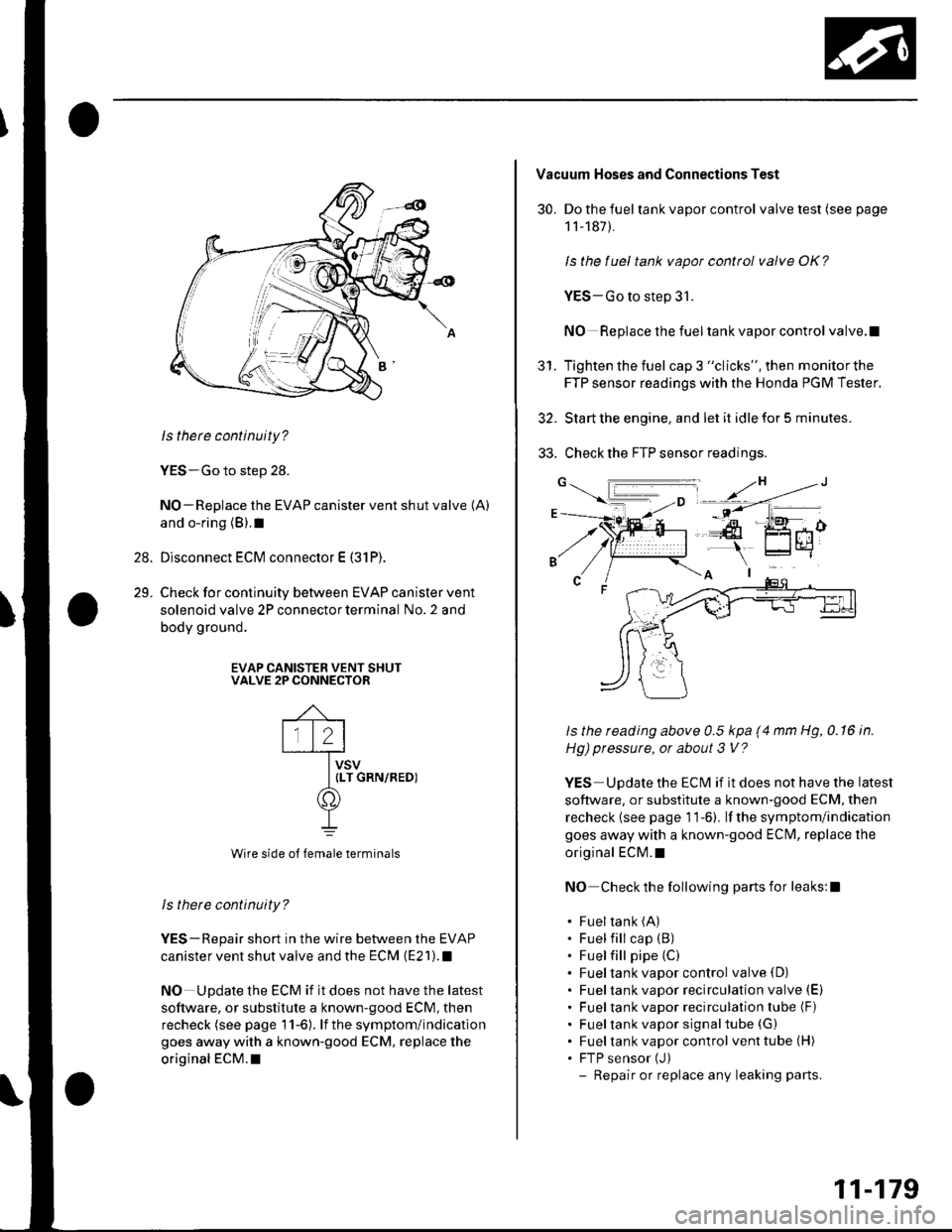
28.
29.
ls thete continuity?
YES-Go to step 28.
NO-Replace the EVAP canister vent shut valve (A)
and o-ring (B).1
Disconnect ECM connector E (31P).
Check for continuity between EVAP canister vent
solenoid valve 2P connector terminal No. 2 and
body ground.
EVAP CANISTER VENT SHUTVALVE 2P CONNECTOR
Wire side o{ female terminals
ls there continuity?
YES-Repair short in the wire between the EVAP
canister vent shut valve and the ECM (E21).1
NO Update the ECM if it does not have the latest
soflware, or substitute a known-good ECM, then
recheck (see page 11-6). lf the symptom/indication
goes away with a known-good ECM, replace the
original ECM.I
30.
Vacuum Hoses and Connections Test
Do the fuel tank vapor control valve test (see page
1 1-187).
ls the fuel tank vapot control valve OK?
YES-Go to step 31.
NO Replace the fueltank vapor control valve.l
Tighten the fuel cap 3 "clicks", then monitorthe
FTP sensor readings with the Honda PGM Tester.
Start the engine. and let it idle for 5 minutes.
Check the FTP sensor readings.
ls the reading above 0.5 kpa (4 mm Hg, 0.16 in.
Hg) pressure, or about 3 V?
YES Update the ECM if it does not have the latest
software, or substitute a known-good ECM, then
recheck {see page 1 1-6). lf the symptom/indication
goes away with a known-good ECfvl, replace the
original ECM.t
NO Check the following parts for leaks:l
. Fueltank (A)
. Fuel fill cap (B)
. Fuel fill pipe (C)
. Fueltank vapor control valve(D). Fueltank vapor recirculation valve (E)
. Fueltank vapor recirculation tube (F)
. Fueltank vapor signaltube (G)
. Fueltank vapor control venttube(H). FTP sensor (J)
- Repair or replace any leaking parts.
5t.
11-179
Page 867 of 1139
Gonnectors and Harnesses
a
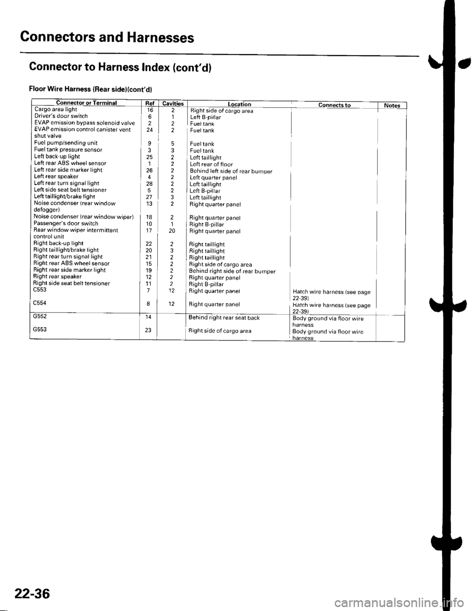
Floor Wire Harness {Rear side}(cont'dl
Cargo areaDriver's door switchEVAP emission bypass solenoid valveEVAP emission control canister ventshut valveFuel pump/sending unitFuel tank pressure sensorLeft back-up lightLeft rear ABS wheel sensorLeft rear side marker lightLeft rear speakerLeft rear turn signal lightLeft side seat belt tensionerLeft taillighVbrake lightNoise condenser (rear windowdefogger)Noise condenser (rear window wiper)Passenger's door switchRear window wiper intermiftentcontrolunitRight back-up lightRight taillighvbrake tightRight rear turn signal lightBight rear ABS wheel sensorRight rear side marker lightRight rear speakerRight side seat belt tensioner
c554
Fueltank
FueltankFueltankLeft taillightLeft rear offloorBehind left side of rear bumperLeft quarter panelLefttaillightLeft B-pillarLeft taillightRight quarter panel
Right quarter panelRight B pillarRight q uarter panel
Right tai ightRight taillightRight taillightRight side of cargo area
side of cargo areaLeft B pillarFueltank
Right quaner panel
6224
I32512642A527'13
181011
222021151912117
I
2122
5322222232
232222212
12
2120
Behind right side of rear bumperRight quaner panelRight B-pillarRight quaner panelHatch wire harness (see page22 39)Hatch wire harness (see page
rear seal bdcl Bodv ground vta
Right side of cargo area Body ground via floor wire
Connector to Harness Index (cont'dl
22-36
Page 879 of 1139
Ground Distribution
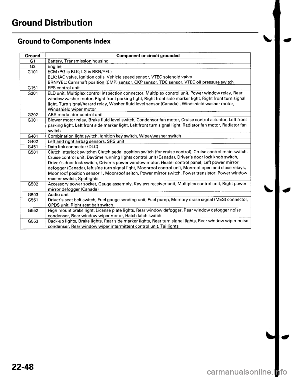
Ground to Components Index
GroundComponent or circuit qrounded
Batterv, Transmission housinq
E ngine
G 101ECM (PG is BLK; LG is BRN/YEL)
BLK: IAC valve, lgnition coils, Vehicle speed sensor, VTEC solenoid valve
BRNA/EL: Camshaft oosition (CMP) sensor. CKP sensor, TDC sensor. VTEC oil pressure switch
G 15'�]EPS control unit
G201ELD unit. Multiplex control inspection connector, Multiplex control unit, Power window relay, Rear
window washer motor, Right front parking light, Right front side marker light, Right front turn signal
light, Turn signal/hazard relay, Washer fluid level sensor (Canada) , Windshield washer motor,
Windshield wiDer motor
G202ABS modulator-control unit
G301
G401
Blower motor relay, Brake fluid level switch, Condensor fan motor, Cruise control actuator, Left front
parking light, Left front side marker light, Left front turn signal light, Radiator fan motor, Radiator fan
swrtcn
Combination liqht switch, lqnitlon kev srvitch, Wiper/wasfrer sr,virch
G402Left and riqht airbaq sensors, SRS unit
G 451Data link connector (DLC)
G501Clutch interlock switchm Clutch pedal position switch (for cruise control), Cruise control main switch,
Cruise control unit, Daytime running lights control unit (Canada), Driver's door lock knob switch,
Driver's door lock switch, Driver's power window motor, Heater control panel, Left power mirror
defogger (Canada), left side turn signal light, Moonroof control unit, Monroof open and close relays,
Moonroof position sensor '1, Moonroof seitch, Power mirror switch, Power transistor, Power window
master switch. SDotliqhts
G502Accessory power socket, Gauge assembly, Keyless receiver unit, lvlultiplex control unit, Right power
mirror defogger {Canada)
G503Audio unit
G551Driver's seat belt switch, Fuel gauge sending unit, Fuel pump, Memory erase signal (IMES) connector,
OPDS unit. Rioht seat belt switch
G552High mount brake light, License plate lights, Rear window defogger, Rear window defogger noise
condenser. Rear window wioer motor, Hatch latch switch
Back-up lights, Brake lights, Rear side marker lights, Rear turn signal lights, Rear window wiper noise
condenser, Rear window wiper intermittent control unit, Taillights
22-48
Page 885 of 1139
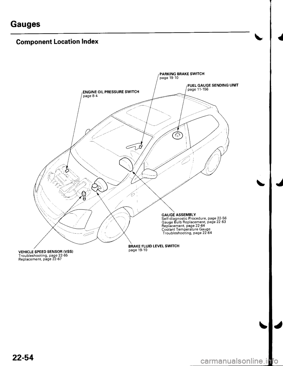
Gauges
\-Component Location Index
PARKING BRAKE SWITCHpage 19-10
FUEL GAUGE SENDINGpage 11-156ENGINE OIL PRESSURE SWITCHpage 8-4
GAUGE ASSEMBLYSelJ-diaqnostic Procedure, page 22-56Gauqe dulb Replacement, page 22 63Rep6cement, page 22-64Coolant Temperature GaugeTroLrbleshooting, page 22'64
BRAKE FLUID LEVEL SWITCHpage 19-10VEHICLE SPEED SENSOR {VSS)Troubleshooting, page 22-65Beplacement, page 22-67
22-54
\
Page 1133 of 1139
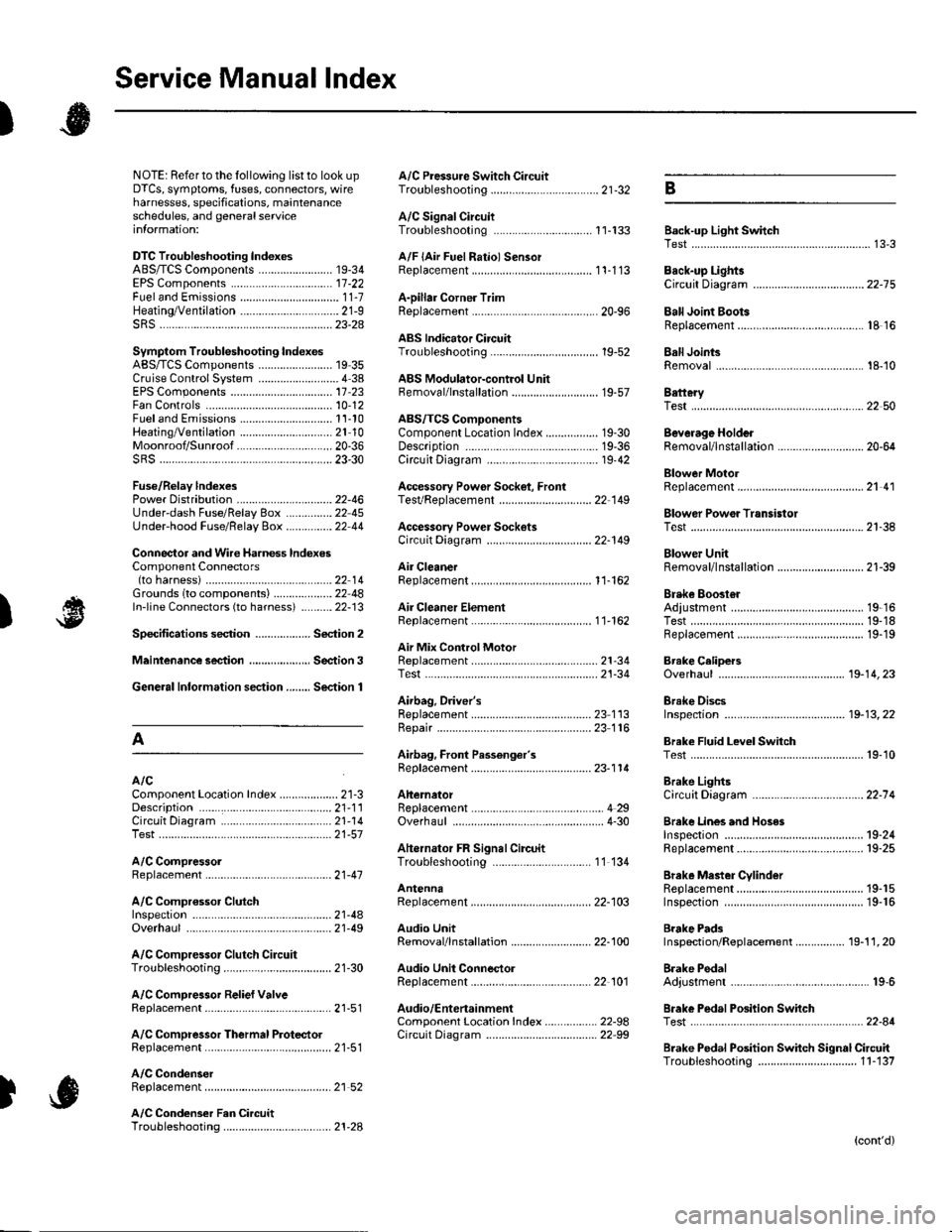
Service Manual lndex
)s
NOTE: Referto the lollowing listto look up A/C Pressure Switch CircuitDTCS, symptoms, fuses, connectors, wire Troubleshooting ......... ...-.-....-...-.-.-....-..21-32 Bharnesses, specifications, maintenanceschedules, and general serviceinlormation:
DTC Troubleshooting Indexes
A/C Signal CircuitTroubleshooting.........................-...... 11-'133 Back-up Light SwitchTest .......................................................... 13'3A/F lAir Fuel Ratiol SensorABS/TCS Components ........................ 19-34 Replacement ....................................... 1 1-113 Back-up Li9ht3EPS Components ................................. '17-22 Circuit DiagramFueland Emissions11-i A-Dillar Corner Trim
ABS Indicator Circuit
Heating/Ventilation ................................ 21-9 Replacement ...............-.....-..............-.... 20,96 Ball Joint BootssRS ........................................................ 23-28Replacement ......
... 19-52 Ball Joints
22-75
18 16
Remova1.............-.......... . ...........18-10Symptom Troubleshooting Indexes TroubleshootingABS/TCSComponents........................ 19 35Cruise Control System ..........................4 38 ABS Modulator-contml UnitEPS Components ................................. 17-23 Bemoval/lnstallation ............................ 19-57 BettervFan Controls10,12
Accessory Powor Socket Front
Blowor Pow€r Transistor
.......22 50
Blower UnitRemoval/lnstallation ............................ 21-39
Fuel and Em issions .............................. 11-10 ABS/TCS ComoonentsHeating/Ventilation..............................21 10 Component Location Index ................. 19-30 Beverage Holder
SRS ........................................................ 23'30 CircuitDiaqram.......................... 19'42Blower MotorReplacement .....21 41
21-38
Power 0istribution ...............................22-46 TesVReplacement .............................. 22'149Under-dash Fuse/Relay Box ............... 22 45Under-hood Fuse/Belay Box ...............22 44 Accessory Power Sockets
Fuse/Relay lndexes
(to harness)
Connector and Wire Harness lndexesComponent Connectors
Circuit Oiagram .................................. 22-149
Air Cleaner......2214 Rep1acemen1.....................................11-162
Air MixControl MotorMeintenence section .................... Section 3 Replacement ......................................... 21'34 Brake CelipersTest......................21-34 Overhaul19-14,23Gene.al lnlormation section........ Section 1
21.57
Airbag. Driver's
Ahernator FR Signal CircuitTroubleshooting .... .........-..........11 134
AntennaReplacement
Inspection ............................................. 19-24Rep|acement................. .................... 19-25
Bieke Meder Cylinder
Irake Discs
A
Replacement ....................................... 23 1 'l3 Inspection .................... ................... 19-13,22Repair ...........-...................................... 23 1 16Brake Fluid Level SwitchAirbag. Front Passenger's TestBeplacement....................................... 23-1 14AIC Brake LightsComponent Location fndex ...................21-3 Altemator CircuitDiagram....................................22-74Description.....................................-....21'1'l Beplacement ................ ........................... 4 29CircuitDiagram....................................21-14 Overhaul .................................................4-30 Brake Lines and Hoses
19.10
A/C CompressolReplacement .......-...-............................. 21 -41
A/C Compr€ssor ClulchRep1acement......................................... 19-15.........22-103 Inspection ............................................. 19-16Inspecton........Overhaul ..........
A/C CondenserReplacement,.,
21-442l-49 Audio Unit
Replacement
Brake PadsRemoval/lnstallation .. ........................22-100 Inspection/Rep1acement................ 19-11,20A/C Compressor Clutch CircuitTroubleshooting ................................... 21-30 Audio Unit Connector Brake Pedal22101 Adjustment..............19,6ArfC Comoressor Relief ValvcReplacement ..........-...-.......................... 21-51 Audio/Entertainment
A/C Compr$sor Thermal Protector Circuit DiagramReplacement............-............................ 21-51
Component Location In dex .................22-9A Test .......-.............. 22-84Breke Pedal Posilion Switch
Brake Pedal Position Switch Signal Clrcuit11-137
.....21 52
A/C Condenser Fan CircuitTroubleshooting ................... . . . . . .....21-28
)s
Troubleshooting
(cont'd)
Page 1135 of 1139
)
Orive BehInspecaron................ 4-26
Door PanelsRemoval/lnstallation -............................. 20-4
Door Sash TrimRep1acement......................................... 20 10
Door StrikersAdiustment ........................................... 20-13
Door Weatherst psBeplacement...........-............................. 20 1 1
EPS Conirol UnitRemoval/1nsta11ation ..................-......... 17-67
EPS Indicator CircuitTroubleshooting ................................... 17 -47
EPS MotorRemoval/lnstallation .-.......................... 17-49
EVAP CanisterRep1acement......................... ......... 11,189
EVAP Control Syst€mComponentLocation Index ..............'11-170
EVAP Two-Wey ValveTest ..........-.............-............................ 11 186
Evaporetor CoreRep1acement........................ . ... 21-42
Evaporator Tomperature SensorReplacement......................................... 21 -37Test..................................... ..........2137
EvaporrtoFHeater UnitReplacement........................................ 21 43
Exhaust ManifoldRemoval/1nsta11ation ................................ I 7
Exhaust Pipe8ep|acement............................................. 9-8
Front SpeakersRep|acement....................................... 22-102
Front SuspensionComponentLocation Index................... 18-3
Fueland EmissionsDescription ........................................... 11-12
Fuel Fill DoorAdjustment ..........-................................ 20 93
Fuel Fill Door OpenetBeplacement........................ . ............ 20.109
Fuel Fill Door Opener CableReplacement....................................... 20- lO7
Fuel FilterReplacement....................................... 1 1-152
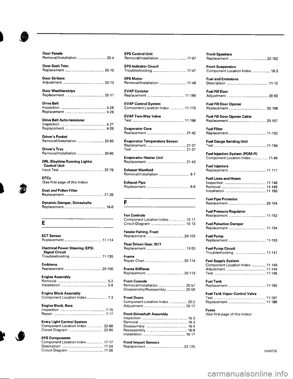
Fuel Gauge Sending UnitTest ......................-.-..........-.................. 11'156
Fuel Injection Syslem (PGM"FIlComponent Location 1ndex................. 11-49
Fuel IniectorsRep1acemen1....................................... 1 1 1 1 l
Fuel Lines and HosesInspection .......................................... 1 1'146Removal ....................... . .. . .... 11-149Insta|1ation .......................................... 1 1 150
FuelPipe ProtectolReplacement....................................... 20-104
Fuel Pressure RegulatotReplacement....................................... 1 1-152
Fuel Pulsation DamperReplacemenl................................... 11 154
Fuel PumpReplacement,,,,,.,.,.,,,.,,,,,,,,,,,,.,.,.,,,..,.. 11-153
Fuel Pump CircuitTroubleshooting -.......-....................... 1 1-141
FuelSupply SystemComponent Location lndex .............. 11 140Adjustment................................... 11-144Test........-...-................. ... ............- 11-145
FuelTankBeplacemenl.............. . ..... .. 11 155
Fuel Tank Vapor ControlValveTest ......................-....... ... . . 11-187Replacement,,.,,...,.,,,.,.,,,,... .. .. 11 189
Fuses{See first page ofthis Index)
)
Rep|acement................. ..................... 4 26
Drive Belt Auto-tensionellnspection ............................................... 4 21Rep1acement.................................... ..4-28
Driver's PocketRemoval/lnstallation -........................... 20-60
Driver's TrayRemoval/lnstallation .........................-.- 20-65
DRL {Daytime Running LightslControl Unitlnput Test .................... ........ . . . ......22-16
DTCs(See first page olthis Index)
Dust and Pollen FillerReplacement......................................... 21-39
Dynamic Damper, DriveshaftsReplacement........................................... 16-8
ECT SensorReplacement.,.,,,.,.,,,,,,,,,,,,,,................ 1 1-1 14
El€ctrical Power Steering IEPS)Signal CircuitTroubleshooting ........ ... .. 11-135
EmblemsReplacement......................-................ 20-100
Engine AssemblyRemova1 .................................................... 5 2Installation ............._.................................. 5-9
Engine Block AssemblyComponent Location Inder ..................... 7.3
Engine Block, BareInspect|onRepair
Fan ControlsComponent Location Index................. 10'l 1Circuit Diagram .. ..... . .. . .................. 10 13
Fender Fairing, FrontReplacement...-................................... 20-103
Final Driven Gear. M/TReplacement.... . . ................................ 13-53
FrameRepair Chan............ ... ....................... 20 11 4
Frame StiffenelReplacement......-................................ 20- J'13
Front ConsoleRemoval/lnstallation ............................ 20 5lDisassembJy/Reassemb|y ................... 20 58
Front DoorsComponent Location Index................... 20-2Adiustment ........................................... 20.12
Front Driveshaft AssemblyInspeclion .................... ... ....16 3Remova1...................-...... ... .....16-3Disassembly ............................... .....165Resassemb|y ................................-......... 16-9Insta11arion ........................ ...... ............ l6 17
Front lmpact SensorsRep1acement............................ ...23 125
................7-15................1 11
)
Entry Light Control SystemComponent Location Index ...............-. 22-89Circuit Dia9ram .................................... 22 90
EPS ComponentsComponent Location 1ndex..........-...... 17-!7Description ........................ ...... ..17-24Circuit Diagram11 26(cont'd)