fuse diagram HONDA CIVIC 2002 7.G Owner's Manual
[x] Cancel search | Manufacturer: HONDA, Model Year: 2002, Model line: CIVIC, Model: HONDA CIVIC 2002 7.GPages: 1139, PDF Size: 28.19 MB
Page 983 of 1139
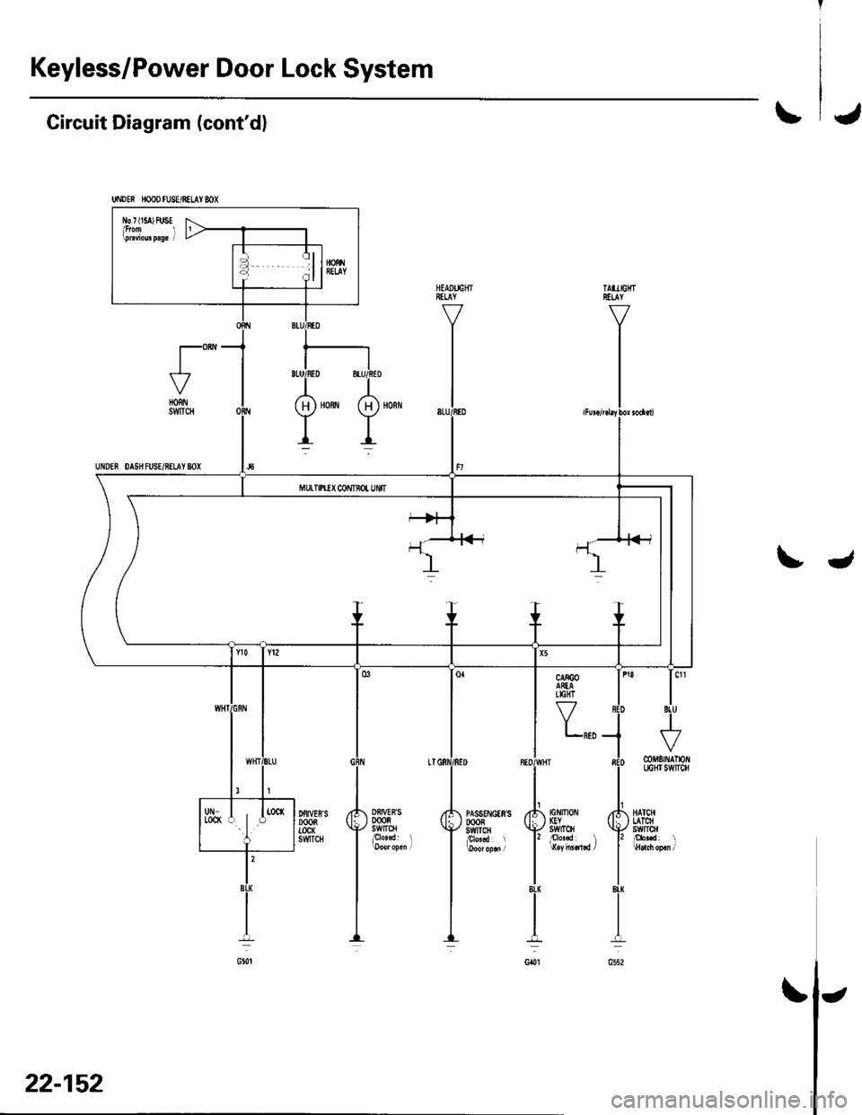
Keyless/Power Door Lock System
UNDEN HOOD FU8E/BELAY MX
l\b r t15a) FUSE
Circuit Diagram (cont'dl\J
t"-HORNSWTCH
UNDEN DAS}I FUSE/8ELAY 8OX
tJ
Y,,,
Df,IVEB'S0008swtrcHplo'.d l
DFIVES'SDOOBTOCK6WTCH
tG tltot IGYstvrTcH
mMErNAlloflLIGHI SWITCH
HATCHLATCHswlrol
22-152
\
Page 995 of 1139
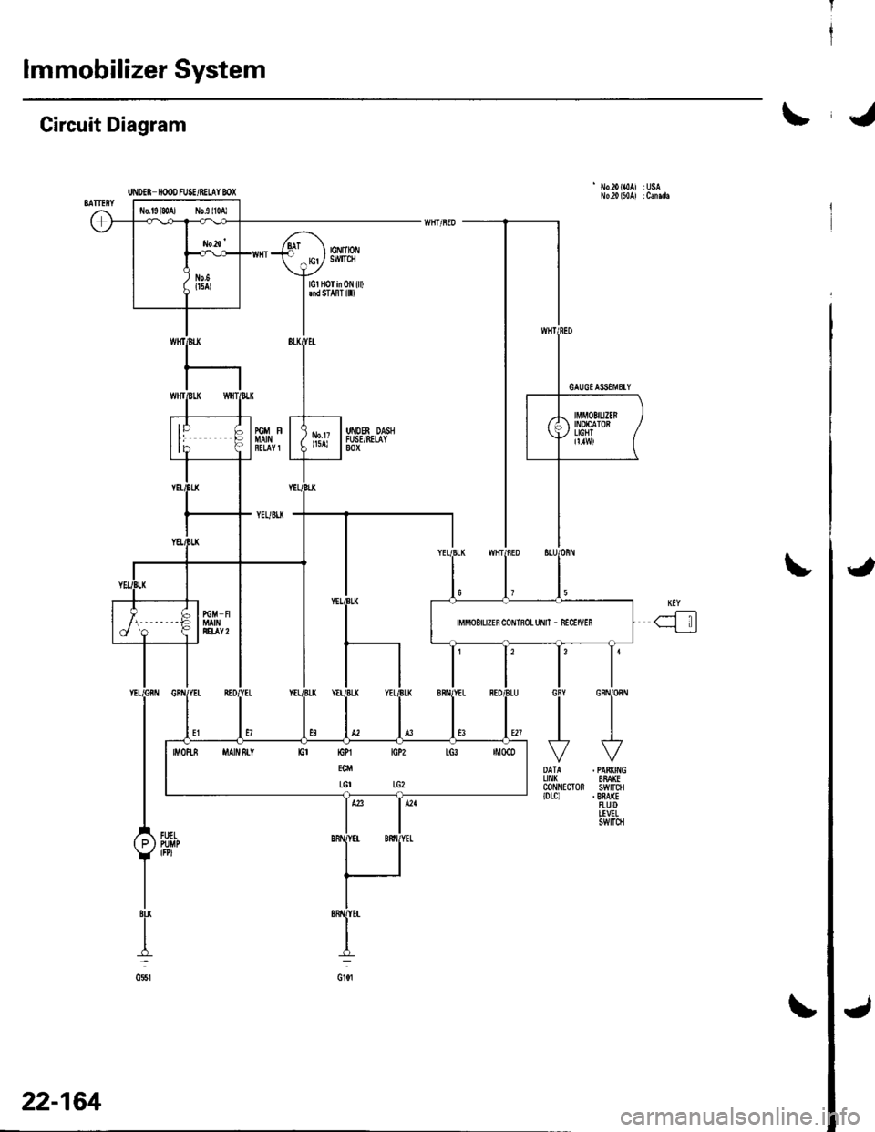
lmmobilizer System
J
I
UNDTR rcOD FUSE/RELAY 8OX
rGNtTt0i/swlrcH
lct HoT in 0N {ll).nd SIAnT l|l)
0R8 itAWStY tct tGPl tGPz LG3 |M0CD
EC
LGI LG2
t
' No20(LAl r USA
Circuit Diagram
FGN
8ELAY1
YEUBIJ(
t
DATA . PA8(II'IGLIN( SMIGCONNECIOR SWITCH{0Lcl .8nA{EFTUIDI!VELSWTfi
22-164
\J
Page 1000 of 1139

ICircuit Diagram
' I'10.20 {a0AJ :usAib.a)l50A) :C.nd.IGNITiON SWITCH
/ BAI \--_to oJ- BLI,'YEL tcl ./
J
G201
HAICIILATCHSWITCH
{cont'd)
UiIDM HOOD IUSE/NEUY BOX
MULTIPLEXc0NT80rtNsPECTror!CONNECIOF
UNDEf, DASHFUSE/NEUYBOX
22-169
Page 1133 of 1139
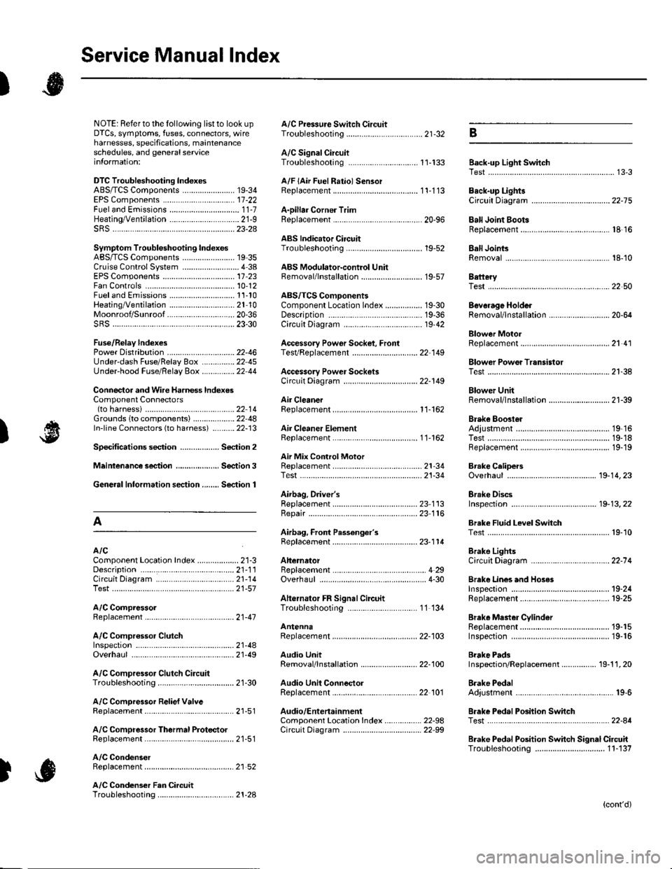
Service Manual lndex
)s
NOTE: Referto the lollowing listto look up A/C Pressure Switch CircuitDTCS, symptoms, fuses, connectors, wire Troubleshooting ......... ...-.-....-...-.-.-....-..21-32 Bharnesses, specifications, maintenanceschedules, and general serviceinlormation:
DTC Troubleshooting Indexes
A/C Signal CircuitTroubleshooting.........................-...... 11-'133 Back-up Light SwitchTest .......................................................... 13'3A/F lAir Fuel Ratiol SensorABS/TCS Components ........................ 19-34 Replacement ....................................... 1 1-113 Back-up Li9ht3EPS Components ................................. '17-22 Circuit DiagramFueland Emissions11-i A-Dillar Corner Trim
ABS Indicator Circuit
Heating/Ventilation ................................ 21-9 Replacement ...............-.....-..............-.... 20,96 Ball Joint BootssRS ........................................................ 23-28Replacement ......
... 19-52 Ball Joints
22-75
18 16
Remova1.............-.......... . ...........18-10Symptom Troubleshooting Indexes TroubleshootingABS/TCSComponents........................ 19 35Cruise Control System ..........................4 38 ABS Modulator-contml UnitEPS Components ................................. 17-23 Bemoval/lnstallation ............................ 19-57 BettervFan Controls10,12
Accessory Powor Socket Front
Blowor Pow€r Transistor
.......22 50
Blower UnitRemoval/lnstallation ............................ 21-39
Fuel and Em issions .............................. 11-10 ABS/TCS ComoonentsHeating/Ventilation..............................21 10 Component Location Index ................. 19-30 Beverage Holder
SRS ........................................................ 23'30 CircuitDiaqram.......................... 19'42Blower MotorReplacement .....21 41
21-38
Power 0istribution ...............................22-46 TesVReplacement .............................. 22'149Under-dash Fuse/Relay Box ............... 22 45Under-hood Fuse/Belay Box ...............22 44 Accessory Power Sockets
Fuse/Relay lndexes
(to harness)
Connector and Wire Harness lndexesComponent Connectors
Circuit Oiagram .................................. 22-149
Air Cleaner......2214 Rep1acemen1.....................................11-162
Air MixControl MotorMeintenence section .................... Section 3 Replacement ......................................... 21'34 Brake CelipersTest......................21-34 Overhaul19-14,23Gene.al lnlormation section........ Section 1
21.57
Airbag. Driver's
Ahernator FR Signal CircuitTroubleshooting .... .........-..........11 134
AntennaReplacement
Inspection ............................................. 19-24Rep|acement................. .................... 19-25
Bieke Meder Cylinder
Irake Discs
A
Replacement ....................................... 23 1 'l3 Inspection .................... ................... 19-13,22Repair ...........-...................................... 23 1 16Brake Fluid Level SwitchAirbag. Front Passenger's TestBeplacement....................................... 23-1 14AIC Brake LightsComponent Location fndex ...................21-3 Altemator CircuitDiagram....................................22-74Description.....................................-....21'1'l Beplacement ................ ........................... 4 29CircuitDiagram....................................21-14 Overhaul .................................................4-30 Brake Lines and Hoses
19.10
A/C CompressolReplacement .......-...-............................. 21 -41
A/C Compr€ssor ClulchRep1acement......................................... 19-15.........22-103 Inspection ............................................. 19-16Inspecton........Overhaul ..........
A/C CondenserReplacement,.,
21-442l-49 Audio Unit
Replacement
Brake PadsRemoval/lnstallation .. ........................22-100 Inspection/Rep1acement................ 19-11,20A/C Compressor Clutch CircuitTroubleshooting ................................... 21-30 Audio Unit Connector Brake Pedal22101 Adjustment..............19,6ArfC Comoressor Relief ValvcReplacement ..........-...-.......................... 21-51 Audio/Entertainment
A/C Compr$sor Thermal Protector Circuit DiagramReplacement............-............................ 21-51
Component Location In dex .................22-9A Test .......-.............. 22-84Breke Pedal Posilion Switch
Brake Pedal Position Switch Signal Clrcuit11-137
.....21 52
A/C Condenser Fan CircuitTroubleshooting ................... . . . . . .....21-28
)s
Troubleshooting
(cont'd)
Page 1135 of 1139
)
Orive BehInspecaron................ 4-26
Door PanelsRemoval/lnstallation -............................. 20-4
Door Sash TrimRep1acement......................................... 20 10
Door StrikersAdiustment ........................................... 20-13
Door Weatherst psBeplacement...........-............................. 20 1 1
EPS Conirol UnitRemoval/1nsta11ation ..................-......... 17-67
EPS Indicator CircuitTroubleshooting ................................... 17 -47
EPS MotorRemoval/lnstallation .-.......................... 17-49
EVAP CanisterRep1acement......................... ......... 11,189
EVAP Control Syst€mComponentLocation Index ..............'11-170
EVAP Two-Wey ValveTest ..........-.............-............................ 11 186
Evaporetor CoreRep1acement........................ . ... 21-42
Evaporator Tomperature SensorReplacement......................................... 21 -37Test..................................... ..........2137
EvaporrtoFHeater UnitReplacement........................................ 21 43
Exhaust ManifoldRemoval/1nsta11ation ................................ I 7
Exhaust Pipe8ep|acement............................................. 9-8
Front SpeakersRep|acement....................................... 22-102
Front SuspensionComponentLocation Index................... 18-3
Fueland EmissionsDescription ........................................... 11-12
Fuel Fill DoorAdjustment ..........-................................ 20 93
Fuel Fill Door OpenetBeplacement........................ . ............ 20.109
Fuel Fill Door Opener CableReplacement....................................... 20- lO7
Fuel FilterReplacement....................................... 1 1-152
Fuel Gauge Sending UnitTest ......................-.-..........-.................. 11'156
Fuel Injection Syslem (PGM"FIlComponent Location 1ndex................. 11-49
Fuel IniectorsRep1acemen1....................................... 1 1 1 1 l
Fuel Lines and HosesInspection .......................................... 1 1'146Removal ....................... . .. . .... 11-149Insta|1ation .......................................... 1 1 150
FuelPipe ProtectolReplacement....................................... 20-104
Fuel Pressure RegulatotReplacement....................................... 1 1-152
Fuel Pulsation DamperReplacemenl................................... 11 154
Fuel PumpReplacement,,,,,.,.,.,,,.,,,,,,,,,,,,.,.,.,,,..,.. 11-153
Fuel Pump CircuitTroubleshooting -.......-....................... 1 1-141
FuelSupply SystemComponent Location lndex .............. 11 140Adjustment................................... 11-144Test........-...-................. ... ............- 11-145
FuelTankBeplacemenl.............. . ..... .. 11 155
Fuel Tank Vapor ControlValveTest ......................-....... ... . . 11-187Replacement,,.,,...,.,,,.,.,,,,... .. .. 11 189
Fuses{See first page ofthis Index)
)
Rep|acement................. ..................... 4 26
Drive Belt Auto-tensionellnspection ............................................... 4 21Rep1acement.................................... ..4-28
Driver's PocketRemoval/lnstallation -........................... 20-60
Driver's TrayRemoval/lnstallation .........................-.- 20-65
DRL {Daytime Running LightslControl Unitlnput Test .................... ........ . . . ......22-16
DTCs(See first page olthis Index)
Dust and Pollen FillerReplacement......................................... 21-39
Dynamic Damper, DriveshaftsReplacement........................................... 16-8
ECT SensorReplacement.,.,,,.,.,,,,,,,,,,,,,,................ 1 1-1 14
El€ctrical Power Steering IEPS)Signal CircuitTroubleshooting ........ ... .. 11-135
EmblemsReplacement......................-................ 20-100
Engine AssemblyRemova1 .................................................... 5 2Installation ............._.................................. 5-9
Engine Block AssemblyComponent Location Inder ..................... 7.3
Engine Block, BareInspect|onRepair
Fan ControlsComponent Location Index................. 10'l 1Circuit Diagram .. ..... . .. . .................. 10 13
Fender Fairing, FrontReplacement...-................................... 20-103
Final Driven Gear. M/TReplacement.... . . ................................ 13-53
FrameRepair Chan............ ... ....................... 20 11 4
Frame StiffenelReplacement......-................................ 20- J'13
Front ConsoleRemoval/lnstallation ............................ 20 5lDisassembJy/Reassemb|y ................... 20 58
Front DoorsComponent Location Index................... 20-2Adiustment ........................................... 20.12
Front Driveshaft AssemblyInspeclion .................... ... ....16 3Remova1...................-...... ... .....16-3Disassembly ............................... .....165Resassemb|y ................................-......... 16-9Insta11arion ........................ ...... ............ l6 17
Front lmpact SensorsRep1acement............................ ...23 125
................7-15................1 11
)
Entry Light Control SystemComponent Location Index ...............-. 22-89Circuit Dia9ram .................................... 22 90
EPS ComponentsComponent Location 1ndex..........-...... 17-!7Description ........................ ...... ..17-24Circuit Diagram11 26(cont'd)
Page 1139 of 1139
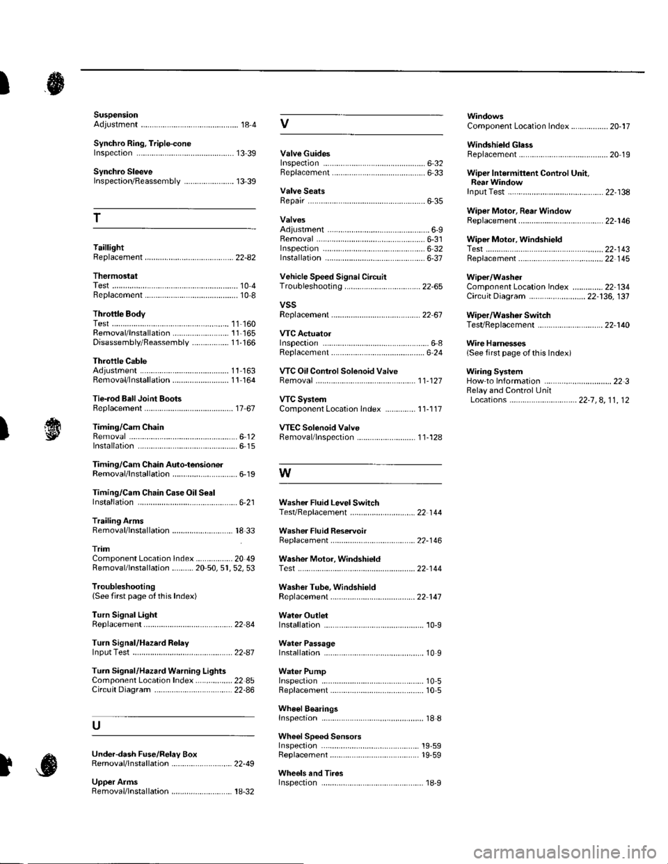
SuspensionAdjustment................-............................184 VComponent Location Index................. 20-17
Windshield GlessReplacement............-..............-............. 20 19
Synchro Ring, Triple-coneInspection...............-..........................1339 ValveGuides
Synchro SleeveInspectaon/Reassemb1y ....................... 13 39
Inspection ............-.-................................ 6 32Beplacement ..........-................................ 6 33 Wiper Intermittent Control Unit,Rear WindowInput Test
T
Valve SeatsRepair ...................................................... 6 35.....22-134
WiDer Motor, Rear WindowRep1acement....................................... 22-1 46Adjustment .-.-.......Removal ...-...-......................................-... 6-31 WiDer Motor, windshield6-9
.....6-32 Test.......-..........-.....-.............................22-143Taillight
ThermostaiTest ........................
Inspec!on
Vehicle Speed Signal Circuit
VTC System
Wiper/WasheI
Wi.ing System
10 4 Troubleshooting .....-... ..........................22-65 Component Location In dex ..............22-134Replacement.....-...-....... ...................... 10 IvssThrottle BodyTest ..................Removal/lnstallation .. . . . . . .. ... 11-'165 VTC ActuatorDisassembly/Feassemb|y................-11-166 Inspection
Circuit Diagram .......................... 22-136, 131
Replacement -.............. ............ .............22 61 Wiper/Washor SwitchTesVReplacement .............................. 22-1 40
.................68 WireHarnesses
11-160
Replacement ........................................... 6 24 (Seefirstpageofthislndex)Throttle CableAdjustment ...... ...-.................... 11163 VTC Oil ConlrolSolenoid ValveRemoval/1nsta11ation..........................11164 Removal....-...-... |1-127 HowtoIn{ormation ...............................223Belay and Control UnitLocations .-....-.............. -.-.-....- 22-7, 4, 1 1, 12Beplacement.........-............................... 1767 ComponentLocationlndex.............. 11-117Tie-rod Ball Joint Boots
lnstallation
Replacement
Turn Signal/Hazard Relay
tsTiming/Cam ChainVTEC Solenoid Valve...612 Femoval/lnspection....-......................11-128................ 6 15
Timing/Cam Chain Auto-tensionelRemoval/1nsta11ation..............................6-19 W
Troubleshooting{See first page ot this Index)
Turn Signal Light
Timing/Cam Chain CaseOil SealInstallation......................-......................6,21 Washer Fluid Level SwitchTesVReplacement .............................. 22 1 44Trailing ArmsRemoval/lnstallation .............. . . . . ..... 18 33 Washer Fluid ReservoirReplacement ....................................... 22-1 46tnmComponent Location lndex ................- 20 49 Washer Motor, WindshieldRemoval/lnstallation ..-.......20 50,51,52,53 Test -..............-.............. ........................22 144
Washer Tube, WindshieldReplacement......-...-............................ 22 1 47
W.ter Outlet.........22 A4 Installation ..................-........................... '10-9
InputTest........22-87 lnstallation................ 10IWeter Passage
Wheels andTires
Turn Signal/Hazard Warning Lights Water PumpComponent Location In dex .................22 85 Inspection ........................... .. . . . ....... 10 5Circu it Diagram ................-................... 22-86 Replacement .-......................................... 10 5
U
WheelBearingsInspec|ion ....................................... ....... 18 8
Wheel Speed SensorsInspection ..-..,.,.,,.,,,,,.,.,,,...................... 19-59Replac€ment ........-....... . . . . . . .. -.... 19-59UndeFdash Fuse/R€lay BoxRemoval/lnstaf lation ............................ 22-49
Upper ArmsRemoval/|nsta11ation................. ... 18-32
],sInspect|on