steering wheel HONDA CIVIC 2002 7.G Owner's Guide
[x] Cancel search | Manufacturer: HONDA, Model Year: 2002, Model line: CIVIC, Model: HONDA CIVIC 2002 7.GPages: 1139, PDF Size: 28.19 MB
Page 557 of 1139
EPS Components
4
17.
18.
Steering Gearbox Installation (cont'dl
Install the motor on the steering gearbox (see page
17-49).
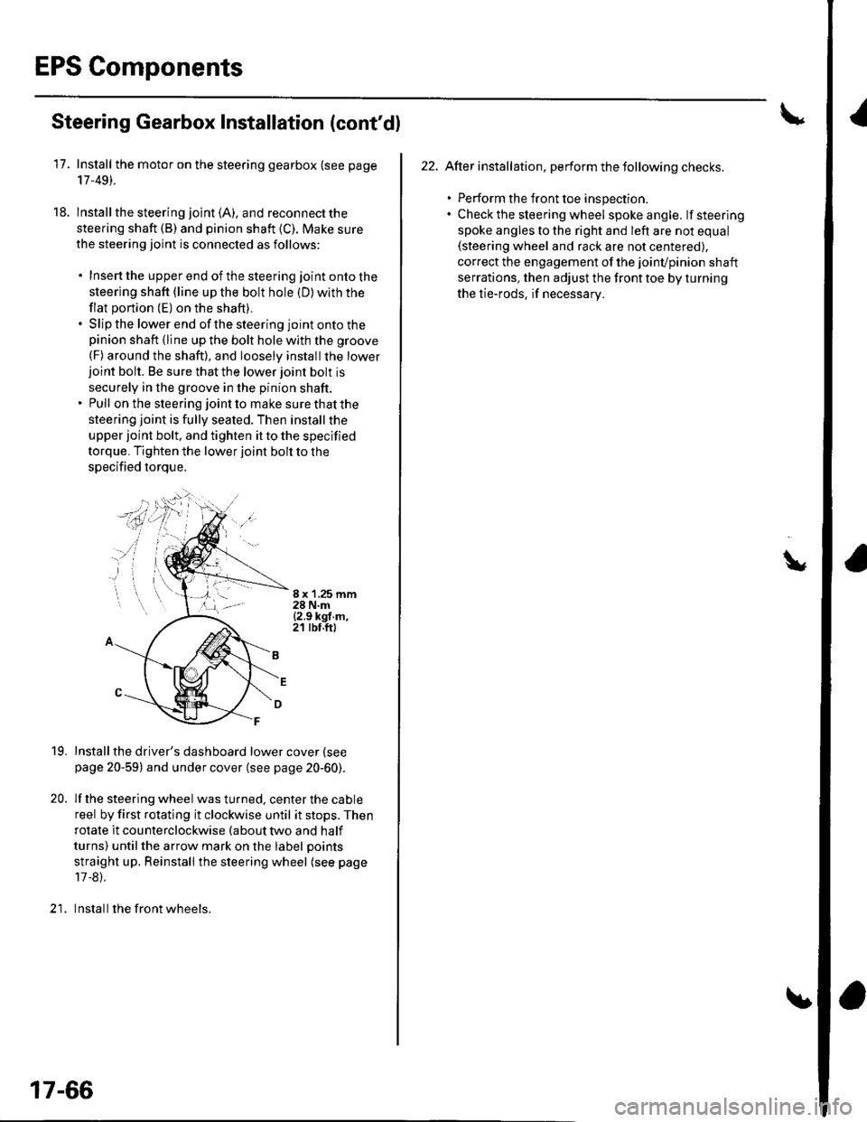
lnstall the steering joint (A). and reconnect the
steering shaft (B) and pinion shaft (C). Make sure
the steering joint is connected as follows:
. Insertthe upperend of thesteering jointontothe
steering shaft (line up the bolt hole (D) with the
flat portion (E) on the shaft).. Slip the lower end of the steering joint onto thepinion shaft (line up the bolt hole with the groove
(F) around the shaft), and loosely installthe lowerjoint bolt. Be sure that the lower joint bolt is
securely in the groove in the pinion shaft.. Pull on the steering joint to make sure that the
steering joint is fully seated. Then install the
upper joint bolt, and tighten it to the specified
torque. Tighten the lower joint bolt to the
specified torque.
8 x '1.25 mm28 N.m{2.9 kgf.m,21 tbt.ft)
19.
20.
Installthe driver's dashboard lower cover (see
page 20-59) and under cover (see page 20-60).
lf the steering wheel was turned, center the cable
reel by first rotating it clockwise until it stops. Then
rotate it counterclockwise (about two and half
turns) untilthe arrow mark on the label points
straight up. Reinstall the steering wheel (see page
17 -8).
Install the front wheels.)1
17-66
22. After installation, perform the following checks.
. Perform the front toe inspection.. Check the steering wheel spokeangle. lfsteering
spoke angles to the right and left are not equal(steering wheel and rack are not centered),
correct the engagement of the joinvpinion shaft
serrations, then adjust the front toe by turning
the tie-rods, if necessarv.
\
Page 558 of 1139
EPS Control Unit Removal/
Installation
1. Remove the passenger's under panel.
2. Turn up the floor carpel, remove lhe EPS control
untr.
Disconnect the EPS control unit connectors.
lnstallthe EPS control unit in the reverse order of
removal.
After installation, start the engine, and let it idle.
Turn the steering wheelfrom lock-to-lock several
times. Check that the EPS indicator does not come
on.
3.
E
Tie-rod Ball Joint Boot Replacement
Special Tool Required
Attachment, 42 mm 07OAD-P0A0100
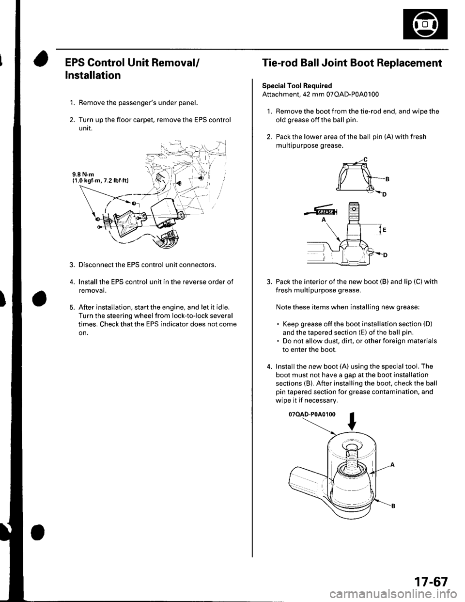
l. Remove the boot from the tie-rod end, and wipe the
old grease off the ball pin.
2. Pack the lower area of the ball pin(A)wilhfresh
mulr purpose grease.
3. Pack the interior of the new boot (B) and lip (C) with
fresh multipurpose grease.
Note these items when installing new grease;
. Keep grease offthe boot installation section (D)
and the tapered section (E) of the ball pin.
. Do not allow dust, dirt, or other foreign materials
to enter the boot.
4. Installthe new boot (A) using the specialtool. The
boot must not have a gap at the boot installation
sections (B). After installing the boot. check the ball
pin tapered section for grease contamination, and
wipe it if necessary.
07(lAD-P0A0100
*-4
r/ \-,d______i.l+_D
-6rA
17-67
Page 565 of 1139
Front Toe Inspection/Adjustment
Use commercially-available computerized four wheel
alignment equipment to measure wheel alignment(caster, camber, toe, and turning angle). Follow the
equipment manufacturer's instructions,
1. Center the steering wheel spokes.
2. Checkthetoe. lf it is not with in the specif ication, go
to step 3.
Front toe-in: 0 t 3 mm {0 t 0.12 in.)
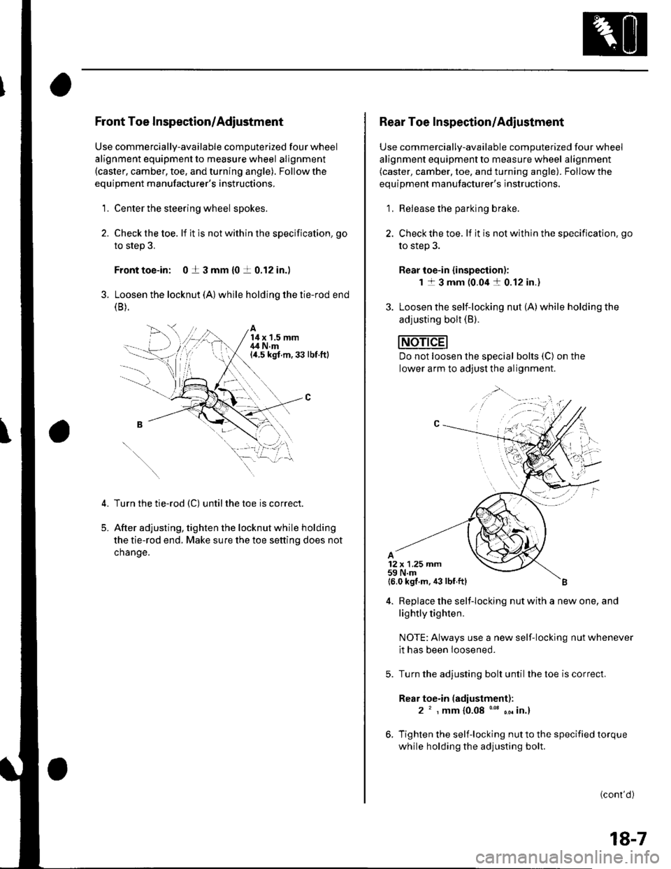
3. Loosen the locknut (A) while holding the tie-rod end(B ).
A14x 1.5 mm,14 N.m(a.5 kgt m,33 lbt.ftl
5.
Turn the tie-rod (C) untilthe toe is correct.
After adjusting, tighten the locknut while holding
the tie-rod end. Make sure the toe setting does not
change.
1,;
Rear Toe Inspection/Adiustment
Use commercially-available computerized four wheel
alignment equipment to measure wheel alignment(caster, camber, toe, and turning angle). Follow the
equipment manufacturer's instructions.
1, Release the parking brake.
2. Checkthe toe. lf it is not within the specification. go
to step 3.
Rear toe-in {inspection):
1 1 3 mm (0.04 a 0.12 in.)
3. Loosen the self-locking nut (A)while holding the
adjusting bolt (B).
Do not loosen lhe special bolts (C) on the
lower arm to adjust the alignment.
4. Replace the self-locking nut with a new one, and
lightly tighten.
NOTE: Always use a new self-locking nut whenever
it has been loosened.
Turn the adjusting bolt until the toe is correct.
Rear toe.in (adiustment):
2 ' , mm {0.08 "' ,. in.}
Tighten the self-locking nut to the specified torque
while holding the adjusting bolt.
(cont'd )
18-7
Page 566 of 1139
Front and Rear Suspension
Wheel Alignment (cont'dl
Turning Angle Inspection
Use commercially-available computerized four wheel
alignment equipment to measure wheel alignment(caster. camber, toe, and turning angle). Followthe
equiDment manufacturer's instructions.
1. Turn the steering wheel fullytotherightandleft
while applying the brake, and check the turning
angles of both front wheels, lf the turning angle is
not within the specification or the inward turning
angles differ between the right and left side, go to
steD 2.
Turning angle:
lnward: 34'00'+ 2'
Outward: 28'00' {reference)
Check the toe. lf it is correct, but the turning angle
is not within the specification, check ior bent or
damaged suspension components,
18-8
Wheel Bearing End Play Inspec'tion
1. Raise lhe vehicle, and support it with safety stands
in the proper location (see page 1-8). Remove the
wheels.
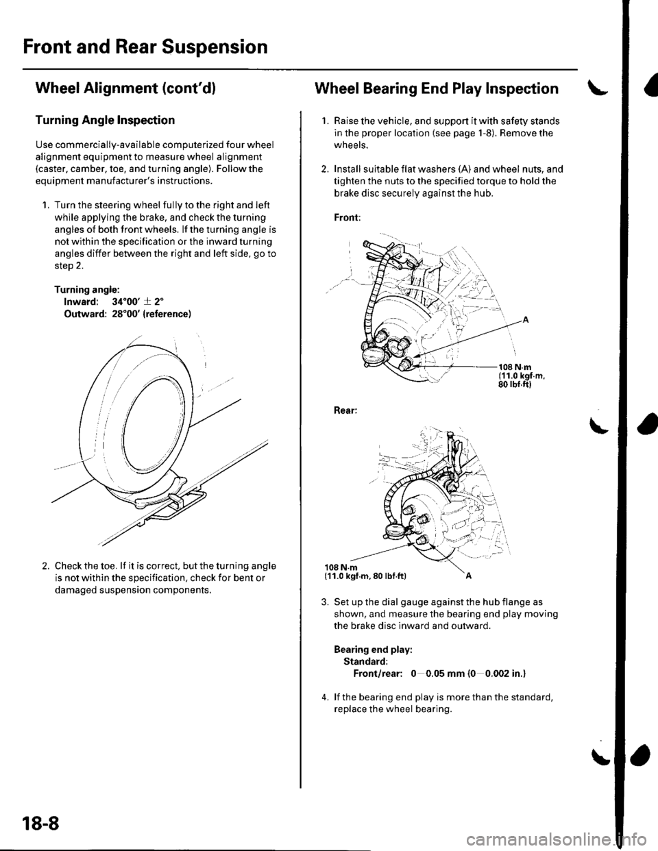
2. Install suita ble f lat washe rs (A) and wheel nuts, and
tighten the nuts to the specified torque to hold the
brake disc securely against the hub.
Front:
108 N.m(11.0 kgf.m,80 rbf.ft)
Rear:
108 N.m
3. Set up the dial gauge against the hub flange as
shown, and measure the bearing end play moving
the brake disc inward and outward.
Bearing end play:
Standard:
Front/rear: 0 0.05 mm {0 0.002 in.}
4. lf the bearing end play is more than the standard,
replace the wheel bearing.
\
(11.0 kgf.m,80 lbf.ft)
Page 579 of 1139
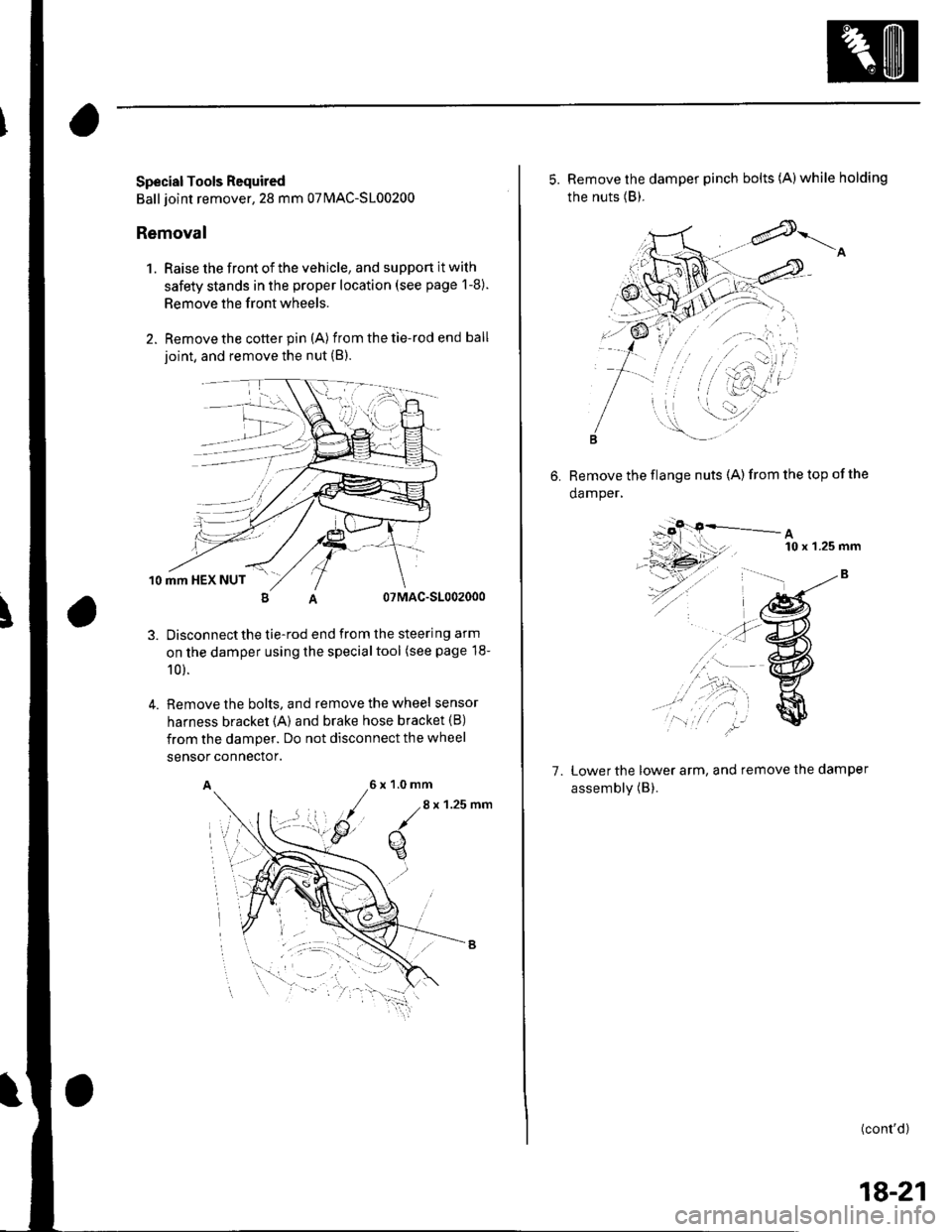
Special Tools Required
Ball joint remover,28 mm 07MAC-S100200
Removal
1. Raise the front of the vehicle, and support it with
safety stands in the proper location (see page 1-8).
Remove the front wheels.
Remove the cotter pin (A) from the tie-rod end ball
ioint, and remove the nut (B).
10 mm HEX NUT
07MAC-S1002000
Disconnectthe tie-rod end from the steering arm
on the damper using the specialtool (see page 18-
10 ).
Remove the bolts, and remove the wheel sensor
harness bracket {A) and brake hose bracket (B)
from the damper. Do not disconnect the wheel
4.
sensor connector.
A6x1.0mm
/.8
x 1.25 nm
q
5. Remove the damper pinch bolts (A)while holding
the nuts (B).
6. Remove the flange nuts (A)from the top ofthe
damper,
A10 x 'l.25 mm
7. Lower the lower arm, and remove the damper
assembly (B).
(cont'd)
18-21
Page 583 of 1139
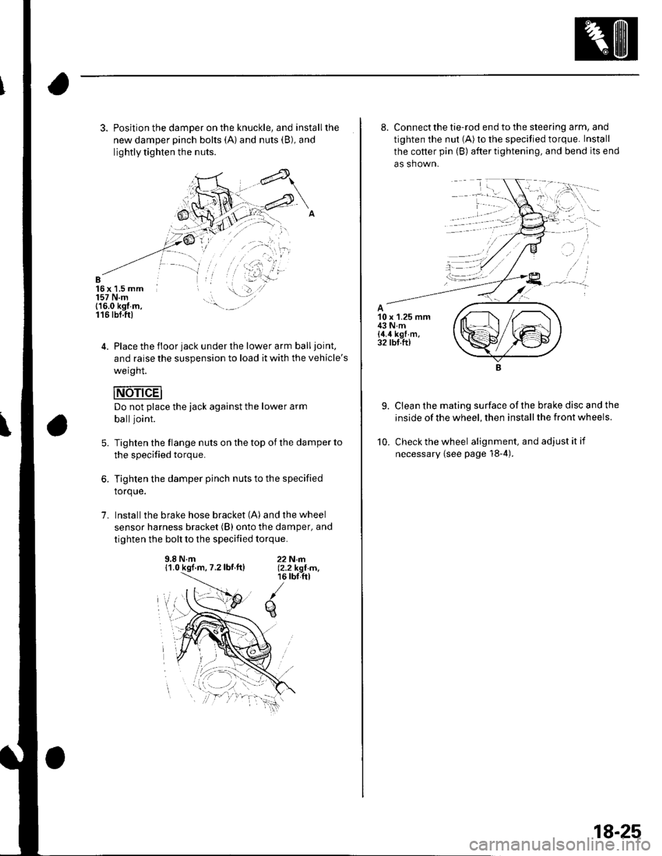
3. Position the damper on the knuckle, and installthe
new damper pinch bolts (A) and nuts (B), and
lightly tighten the nuts.
B16x 1,5 mm157 N.m(16.0 kgt m,116 tbt.ftl
4. Place the floor jack under the lower arm balljoint,
and raise the suspension to load it with the vehicle's
weight.
Do not place the jack against the lower arm
balljoint.
Tighten the flange nuts on the top of the damper to
the specified torque.
Tighten the damper pinch nuts to the specified
torque.
Install the brake hose bracket (A) and the wheel
sensor harness bracket (B) onto the damper, and
tighten the bolt to the specified torque.
5.
1.
9.8 N.m11.0 kgf.m, 7.2lbf.ftl22N|rl.12.2 kgI m,16 rbr,ftl
q
8. Connect the tie-rod end to the steering arm, and
tighten the nut (A) to the specified torque. Install
the cotter pin (B) after tightening, and bend lts end
as shown.
9. Clean the mating surface ofthe brake disc and the
inside of the wheel, then install the front wheels.
10. Check the wheel alignment, and adjustitif
necessary {see page 18-4).
18-25
Page 599 of 1139
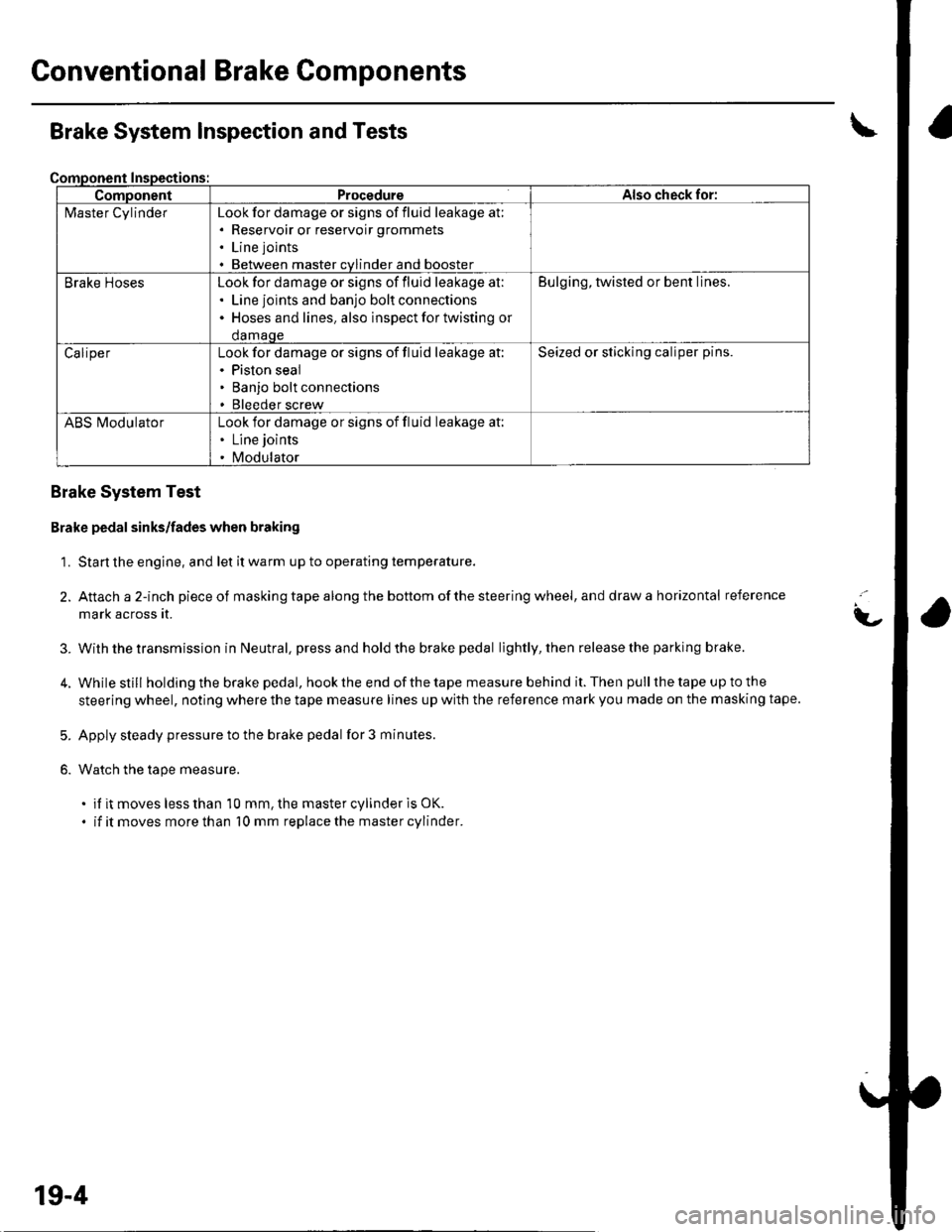
Gonventional Brake Components
ComponentProcedureAlso check for:
l\4aster CylinderLook for damage or signs of fluid leakage at;. Reservoir or reservoir grommets
. Line joints
. Between master cvlinder and booster
Brake HosesLook for damage or signs of fluid leakage at:. Line joints and banjo bolt connections. Hoses and lines. also inspect for twisting or
damaqe
Bulging, twisted or bent lines.
CaliperLook for damage or signs of fluid leakage at:. Piston seal. Banjo bolt connections. Bleeder screw
Seized or sticking caliper pins.
ABS l\ilodulatorLook for damage or signs of fluid leakage at:. Line joints
. Modulator
Brake System Inspection and Tests
Brake System Test
Brake pedal sinks/fades when braking
1. Start the engine, and let it warm up to operating temperature.
2. Attach a 2-inch pieceof masking tape along the bottom of the steering wheel, and draw a horizontal reference
mark across it.
With the transmission in Neutral, press and hold the brake pedal lightly, then release the parking brake.
While still holding the brake pedal, hook the end of the tape measure behind it. Then pull the tape up to the
steering wheel, noting where the tape measure lines up with the reference mark you made on the masking tape.
Apply steady pressure to the brake pedal for 3 minutes.
Watch the tape measure.
. if it moves less than 10 mm, the master cylinder is OK.
. if it moves more than 10 mm replace the master cylinder.
t-
3.
5.
6.
19-4
Page 954 of 1139
I
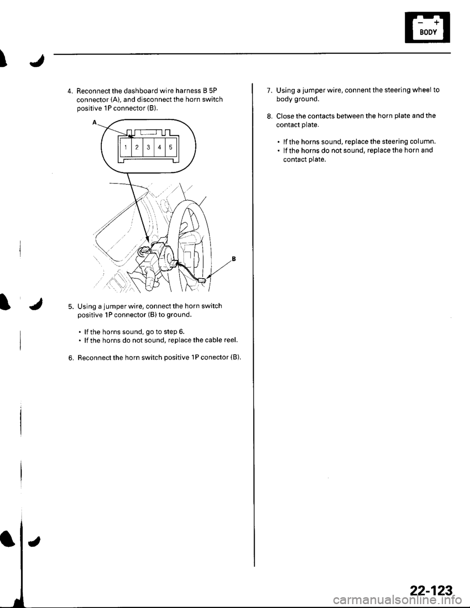
4. Reconnect the dashboard wire harness B 5P
connector {A), and disconnect the horn switch
positive 1P connector (B).
Using a jumperwire, connectthe horn switch
positive 1P connector (B) to ground
. lf the horns sound, go to step 6.. lf the horns do notsound, replacethecable reel.
Reconnect the horn switch positive 1P conector (B).6,
22-123
1.Using a jumper wire, connent the steering wheel to
body ground.
Close the contacts between the horn plate and the
contact plate.
. lf the horns sound, replacethe steering column.. lf the hornsdo notsound, replacethe horn and
contact plate.
8.
Page 1021 of 1139
sRs
Precautions and Procedures
General Precautions
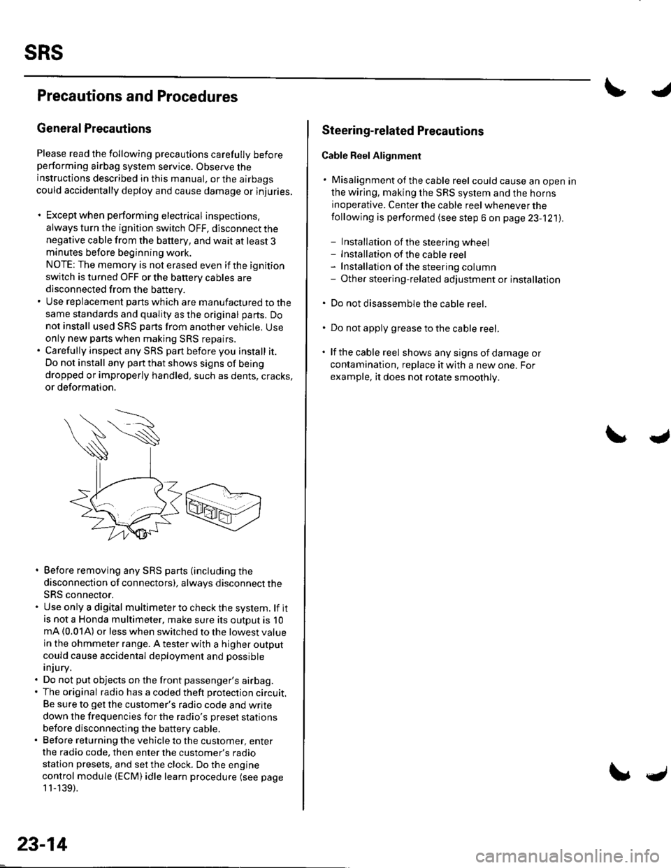
Please read the following precautions carefully beforeperforming airbag system service. Observe theinstructions described in this manual. or the airbags
could accidentally deploy and cause damage or injuries.
. Except when performing electrical inspections.
always turn the ignition switch OFF, disconnect the
negative cable from the battery, and wait at least 3minutes before beginning work.
NOTE: The memory is not erased even if the ignition
switch is turned OFF or the battery cables are
disconnected from the battery.. Use replacement pans which are manufactured to the
same standards and quality as the original parts. Do
not install used SRS parts from another vehicle. Useonly new pans when making SRS repairs.. Carefully inspect any SRS part before you install it.
Do not install any part that shows signs of being
dropped or improperly handled, such as dents, cracks,
or deformation.
. Before removing any SRS parts (including the
disconnection of connectors), always disconnect the
SRS connector.. Use only a digital multimeter to check the system. lf itis not a Honda multimeter, make sure its outout is 10mA (0.01A) or less when switched to the lowest value
in the ohmmeter range. A tester with a higher output
could cause accidental deployment and possible
injury.. Do not put objects on the front passenger's airbag.. The original radio has a coded theft protection circuit.
Be sure to get the customer's radio code and write
down the frequencies for the radio's preset stations
before disconnecting the battery cable.. Before returning the vehicle to the customer, enter
the radio code. then enter the customer's radio
station presets, and set the clock. Do the engine
control module (ECM) idle learn procedure (see page
11-139).
23-14
c
Steering-related Plecautions
Cable Reel Alignment
. Misalignment of the cable reel could cause an open in
the wiring, making the SRS system and the horns
inoperative. Center the cable reel whenever the
following is performed (see step 6 on page 23-121).
- Installation of the steering wheel- Installation of the cable reel- Installation ofthe steering column- Other steering-related adjustment or installation
. Do not disassemble the cable reel.
. Do not apply grease to the cable reel.
. lf the cable reel shows any signs of damage or
contamination. replace it with a new one. For
example, it does not rotate smoothly.
Page 1028 of 1139
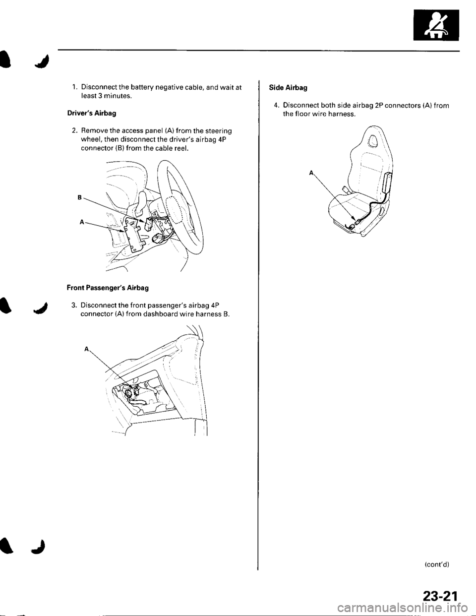
1. Disconnect the battery negative cable, and wait at
least 3 minutes.
Driver's Airbag
2. Remove the access panel (A) from the steering
wheel, then disconnecl the driver's airbag 4P
connector (B)from the cable reer.
Front Passenger's Airbag
3. Disconnect the front passenger's airbag 4P
connector (A)from dashboard wire harness B.
Side Airbag
4. Disconnect both side airbag 2P connectors (Alfrom
the floor wire harness.
(cont'd)
23-21