22-141 HONDA CIVIC 2002 7.G Workshop Manual
[x] Cancel search | Manufacturer: HONDA, Model Year: 2002, Model line: CIVIC, Model: HONDA CIVIC 2002 7.GPages: 1139, PDF Size: 28.19 MB
Page 832 of 1139

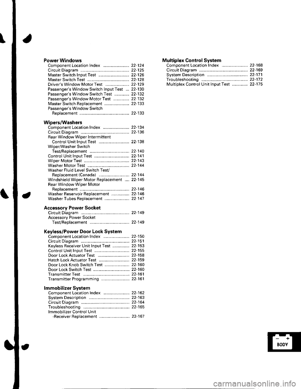
Power WindowsComponent Location Index ..........
circuit Diagram . .. ............... .........:.::::.::::.:Master Switch Input Test ...........................Master Switch TestDriver's Window Motor Test .....................
Passenger's Window Switch lnput Test ...Passenger's Window Switch Test .............
Passenger's Window Motor Test ..............
lMaster Switch Replacement ......................
Passenger's Window SwitchReplacement
Wipers/WashersComponent Location Index .......................
Circuit DiagramRear Window Wiper Intermiftent
Control Unit Input Test ...........................Wiper/Washer SwitchTesVReplacementControl Unit Input Test ...............................Wiper Motor Test
Washer Motor TestWasher Fluid Level Switch TesV
Replacement (Canadal ..........................
Windshield Wiper Motor Replacement ....
Rear Window Wiper MotorReplacementWasher Reservoir Replacement ................
Washer Tubes Beplacement ......................
Accessory Power SocketCircuit Diagram ......... 22-149
Accessory Power Socket
TesVReplacement ................................... 22-1 49
Keyless/Power Door Lock System
Component Location Index ....................... 22-150
Circuit Diagram ......... 22-151Keyless Receiver Unit InputTest ............... 22-153
Control Unit Input Test ............................... 22-155
Door LockActuatorTest .........,.......,..,.,..... 22-158Hatch LockActuatorTest ........................... 22-159
Door Lock Knob Switch Test ...................... 22-160
Door Lock Switch Test ................................ 22-160
Transmitter Test ....... 22-161
Transmitter Programming ......................... 22-161
Multiplex Control SystemComponent Location Index ...........
circuit Diagram ...... ........................::.:..:.::.:
Svstem DescriDtionTroubleshootingMultiolex Control Unit InDut Test .............
22 12422-12522-12622-12822-129
22- t30
22-13222 13222-133
22-133
22-134
22-138
22-14022-14122-14322-144
22-14422-145
22-14622-14622 147
22,16422-16922-17'l22,11222-175
lmmobilizer Systemcomponent Location Index ...........
System Description ....... ............. ..:..:..:.:...
Circuit DiagramTroubleshootinglmmobilizer Control Unit-Receiver Replacement ...........................
22-16222-16322-164
22-167
Page 972 of 1139

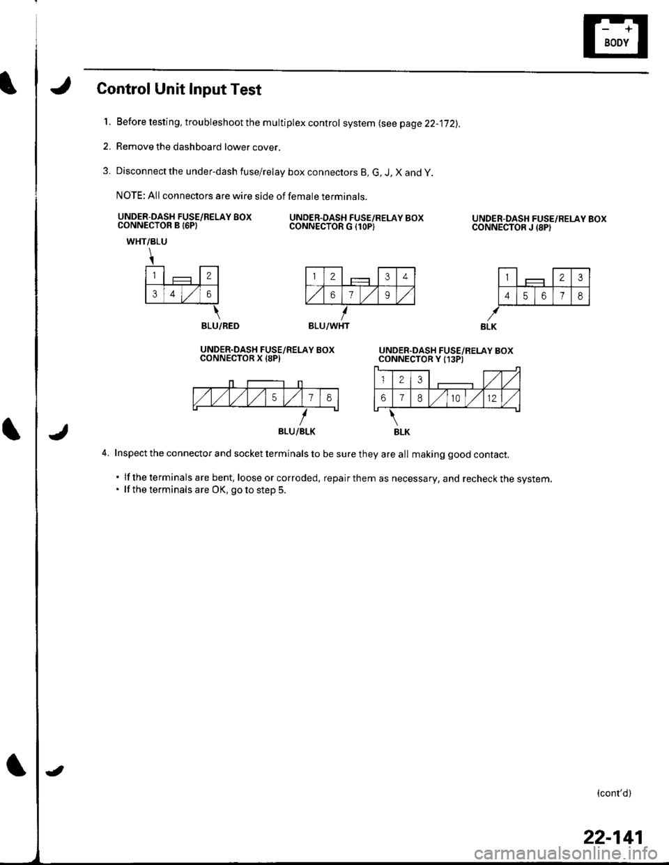
Control Unit Input Test
l.Before testing, troubleshoot the multiplex control system lsee page 22-jj2).
Remove the dashboard lower cover,
Disconnect the under-dash fuse/relay box connectors B, G, J, X and y
NOTE: All connectors are wire side of female terminals.
UNDER-DASH FUSE/RELAY BOXCONNECTOR B I6PIUNDER.DASH FUSE/RELAY BOXCONNECTOR G {1OP)
2.
3.
UNDER-DASH FUSE/RELAY BOXCONNECTOR J {8PI
l-,1 - llTtlF_j-JF-#
141516 7l8l
WHT/BLU
\
l-,1 - l-rl€ll
lslrlzlol
\BLU/RED
UNDER.DASH FUSE/RELAY BOXCONNECTOR X I8PI
4. Inspect the connector and socket terminals to be sure they are all making good contact.
. lf the terminals are bent, loose or corroded, repairthem as necessary, and recheckthe system.. lf the terminals are OK, goto step 5.
(cont'd)
BLU/WHT
BLU/BLK
22-141