Tdc sensor HONDA CIVIC 2002 7.G Workshop Manual
[x] Cancel search | Manufacturer: HONDA, Model Year: 2002, Model line: CIVIC, Model: HONDA CIVIC 2002 7.GPages: 1139, PDF Size: 28.19 MB
Page 99 of 1139
![HONDA CIVIC 2002 7.G Workshop Manual Cylinder Head
Component Location Index (contd)
CAMSHAFT POSITIONICMP} SENSOR
TOP DEAD CENTER(TDC) SENSOR
CAMSHAFTHOLDER
f\
fr
T
F]
Fg
Y
R
LI
CAM CHAINGUIDE B
/EEI
g----- -"-oowetew
EXHAUST CAMSHAFTSP HONDA CIVIC 2002 7.G Workshop Manual Cylinder Head
Component Location Index (contd)
CAMSHAFT POSITIONICMP} SENSOR
TOP DEAD CENTER(TDC) SENSOR
CAMSHAFTHOLDER
f\
fr
T
F]
Fg
Y
R
LI
CAM CHAINGUIDE B
/EEI
g----- -"-oowetew
EXHAUST CAMSHAFTSP](/img/13/5744/w960_5744-98.png)
Cylinder Head
Component Location Index (cont'd)
CAMSHAFT POSITIONICMP} SENSOR
TOP DEAD CENTER(TDC) SENSOR
CAMSHAFTHOLDER
f\
fr
T
F]
Fg
Y
R
LI
CAM CHAINGUIDE B
/EEI
g----- -"-oowetew
EXHAUST CAMSHAFTSPROCKETRemoval, page 6 24Installation, page 6-25
EXHAUST CAMSHAFT
ROCKER ARMASSEMBLYOverhaul, page 6 27Inspection, page 6-28
6-4
Page 118 of 1139
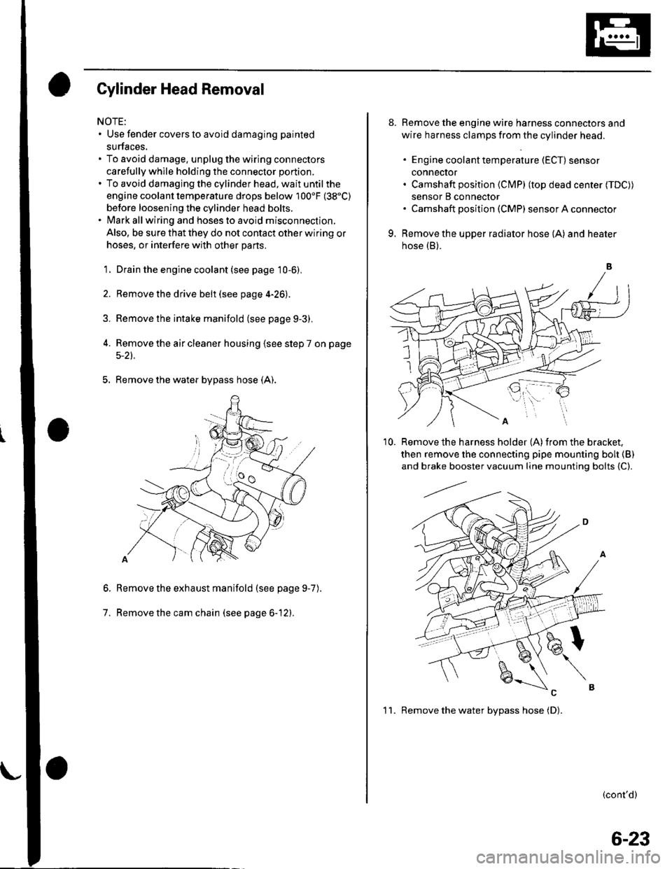
Gylinder Head Removal
NOTE:. Use fender covers to avoid damaging painted
surfaces.
To avoid damage, unplug the wiring connectors
carefully whlle holding the connector portion.
To avoid damaging the cylinder head, wait until the
engine coolant temperature drops below 100'F (38"C)
betore loosening the cylinder head bolts.
Mark all wiring and hoses to avoid misconnection.
Also, be sure that they do not contact other wiring or
hoses, or interfere with other parts.
'1.
2.
3.
Drain the engine coolant (see page 10-6).
Remove the drive belt (see page 4-26).
Remove the intake manifold {see page 9-3).
Remove the air cleaner housing (see step 7 on page
5-2t.
5. Remove the water bypass hose (A).
Remove the exhaust manifold (see page 9-7
Remove the cam chain (see page 6-12).
6.
7.
).
8. Remove the engine wire harness connectors and
wire harness clamps from the cylinder head.
. Engine coolant temperature (ECT) sensor
conneclor. Camshaft position (Cl\4P) (top dead center (TDC))
sensor B connector. Camshaft posilion (CMP) sensor A connector
9. Remove the upper radiator hose (A) and heater
hose (B).
'10. Remove the harness holder (A)from the bracket,
then remove the connecting pipe mounting boh {B)
and brake booster vacuum line mounting bolts {C).
(cont'd)
1 1. Remove the water bvpass hose (D).
6-23
Page 208 of 1139
Fuel and Emissions
Fuel and Emissions Systems
SpecialTools
General Troubleshooting
Information
DTC Troubleshooting lndex ....
Symptom Troubleshooting
1ndex...............
System Descriptions ................
Howto Set Readiness Codes ..
PGM-FlSystem
Component Location Index ....
DTC Troubleshooting ..............
MIL Circuit Troubleshooting ...
DLC Circuit Troubleshooting ..
Injector Replacement ...............
A,/F Sensor Replacement .........
Secondary HO2S
Replacement
ECT Sensor Reolacement .......
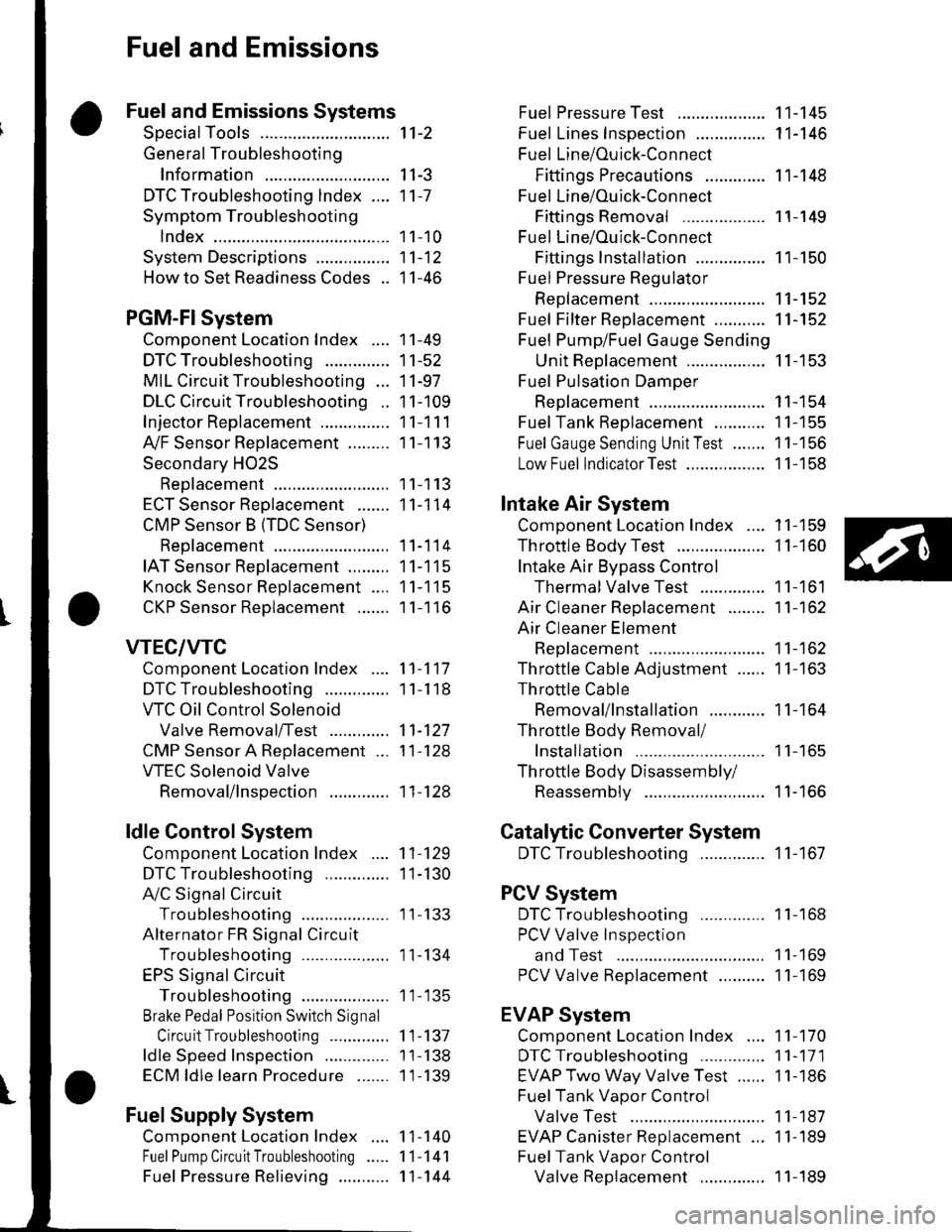
CMP Sensor B {TDC Sensor)
Replacement
IAT Sensor Replacement .........
Knock Sensor Replacement ....
CKP Sensor Reolacement .......
VTEC/VTC
Comoonent Location Index ....
DTC Troubleshooting ..............
VTC Oil Control Solenoid
Valve Removal/Test .............
CMP Sensor A Replacement ...
VTEC Solenoid Valve
Removal/lnsoection .............
ldle Control System
Component Location Index
DTC Troubleshooting ..............
A,/C Signal Circuit
TroubleshootinS ...................
Alternator FR Signal Circu it
TroubleshootinS ...................
EPS Signal Circuit
TroubleshootinS ...................
Brake Pedal Position Switch Signal
Circuit Troubleshooting .............
ldle Speed Inspection
ECM ldle learn Procedure .......
Fuel Supply System
Component Location Index
Fuel Pump Circuit Troubleshooting
1't-2
I I-J
11-7
1 1-10
11-12
11-46
11-49
11-52
11-97
11-109
11-111
11-113
11-113
11-114
11-114
11-115
11-115
11-116
11-117
1 1-1 18
11-127
11-128
11-128
11-129
1I-130
I t- t55
11-134
1 1- 135
1 1-137
1 1-138
1 1-139
1 1-140
11-141
11-144
Fuel PressureTest ................... 11-145
Fuel Lines Inspection ............... 11-146
Fuel Line/Ouick-Connect
Fittings Precautions ............. 1 1-148
Fuel Line/Ou ick-Con nect
Fittings Removal .................. 1 1-149
Fuel Line/Ou ick-Con nect
Fittings lnstallation ............... 11-150
Fuel Pressure Regu lator
Replacement ......................... 11-152
Fuel Fifter Replacement ........... 11-152
Fuel Pump/Fuel Gauge Sending
UnitReDlacement ................. 11-153
Fuel Pulsation Damoer
Rep1acement ......................... 11-154
Fuel Tank Reolacement ........... 11-155
Fuel GaugeSending UnitTest ....... 11-156
Low Fuel lndicatorTest ................. 1 1-158
Intake Air System
Comoonent Location Index .... 11-159
Throttle BodyTest ................... 11-160
Intake Air Bypass Control
Thermal Valve Test .............. 11-161
Air Cleaner Reolacement ........ 11-162
Air Cleaner Element
Reolacement ......................... 11-162
Throttle Cable Adjustment ...... 11-163
Th rottle Cable
Removal/lnstallation ............ 1 1-164
Th rottle Body Removal/
Installation .. 11-165
Th rottle Body Disassembly/
Reassemblv .......................... 11-166
Catalytic Converter System
DTC Troubleshooting .............. 1 1-167
PCV System
DTC Troubleshooting .............. 1 1-168
PCV Valve InsDection
and Test ...... 1 1- 169
PCV Valve Reolacement .......... 11-169
EVAP System
Component Location Index .... 11-170
DTCTroubleshooting .............. 11-171
EVAP Two Way Valve Test ...... 11-186
Fuel Tank Vaoor Control
Valve Test ... 11-187
EVAP Canister Replacement ... 11-189
Fuel Tank Vaoor Control
Valve Reolacement .............. 1 1-189Fuel Pressu re Relieving ...........
Page 216 of 1139
DTC
{MlL indication*l
Temporary DTCDetection ltemPage
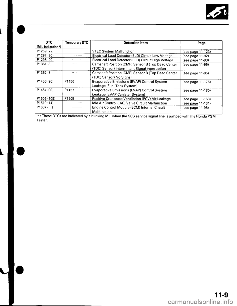
P1259 t22JVTEC System l\4alfunction(see Daqe 11-123)P1291 t20\Electrical Load Detector (ELD) Circuit Low Voltaqe(see Daqe l1-92)P1298 (20)Electrical Load Detector (ELD) Circuit Hiqh Voltaqe(see oaoe 11-93)P1361 (8)Camshaft Position (CMP) Sensor B (Top Dead Center(TDC) Sensor) Intermittent Sional InterruDtion
(see page 11-95)
P1362 (8)Camshaft Position (CMP) Sensor B (Top Dead Center(TDC) Sensor) No Siqnal
(see page 11-95)
P'r456 (90)P1456Evaporative Emissions (EVAP) Control System
Leakaqe (Fuel Tank Svstem)
(see page 11-175)
P14s7 (90)P1457Evaporative Emissions (EVAP) Control System
Leakaqe (EVAP Canister Svstem)
(see page 1'l-180)
P1505 (109)P1505Positive Crankcase Ventilation (PCV) Air Leakaqe(see oaqe 11-1681
P1519 (14)ldle Air Control (lAC) Valve Circuit Malfunction{see paqe 11-131)P1607 ( )Engine Control Module (ECM) Internal Circuit
Malfunction
(see page 1 1-96)
" : These DTCS are indicated by a blinking MIL when the SCS service signal line is jumped with the Honda PGM
Tester.
11-9
Page 223 of 1139
![HONDA CIVIC 2002 7.G Workshop Manual Fuel and Emissions Systems
aSystem Descriptions (contdl
ECM Electrical Connections
\
No. INJECTOR
No,2INJECTOR
No.3 INJEC]OB
No./tINJECTOF
MAPSENSON
TPSENSOR
IATSENSOR
ECTSENSOB
\
CMP SENSOR B(TDC S HONDA CIVIC 2002 7.G Workshop Manual Fuel and Emissions Systems
aSystem Descriptions (contdl
ECM Electrical Connections
\
No. INJECTOR
No,2INJECTOR
No.3 INJEC]OB
No./tINJECTOF
MAPSENSON
TPSENSOR
IATSENSOR
ECTSENSOB
\
CMP SENSOR B(TDC S](/img/13/5744/w960_5744-222.png)
Fuel and Emissions Systems
aSystem Descriptions (cont'dl
ECM Electrical Connections
\
No. INJECTOR
No,2INJECTOR
No.3 INJEC]OB
No./tINJECTOF
MAPSENSON
TPSENSOR
IATSENSOR
ECTSENSOB
\'
CMP SENSOR B(TDC SENSOSJ
CKPSENSOR
11-16
F€VERSE LOCKSOLENOIDVAIVE
\-
Page 227 of 1139
![HONDA CIVIC 2002 7.G Workshop Manual Fuel and Emissions Systems
System Descriptions {contd)
ECM Inputs and Outputs at Connector A (31P)
\. il
Wire side of female terminals
\.
1AFS]TC2
GP2
3IGPl4PG25PG.16AFS+1
CKP
IKS
10SG211sG1
12IACV
HONDA CIVIC 2002 7.G Workshop Manual Fuel and Emissions Systems
System Descriptions {contd)
ECM Inputs and Outputs at Connector A (31P)
\. il
Wire side of female terminals
\.
1AFS]TC2
GP2
3IGPl4PG25PG.16AFS+1
CKP
IKS
10SG211sG1
12IACV](/img/13/5744/w960_5744-226.png)
Fuel and Emissions Systems
System Descriptions {cont'd)
ECM Inputs and Outputs at Connector A (31P)
\. il
Wire side of female terminals
\.
1AFS]TC2
GP2
3IGPl4PG25PG.16AFS+1
CKP
IKS
10SG211sG1
12IACV
'15
TPS16AFS_18
VSS
19IVAP20vcc221vccl
22AFSHTC+
23LG225
Ct\.4PA
26CMPB(rDc)
27IGPLS428IGPLS329IGPLS230IGPLS,I
NOTE: Standard battery voltage is 12 V.
JorminalnumberWirecolor[€rminal namoDescriptionSignal
19GRN/REDMAP (MANIFOLDABSOLUTE PRESSURESENSOR)
Detects MAP sensor signalWith ignition switch ON (ll):about3 VAt idle: about 1.0 V (depending on enginespeed)
20YEUBLUVCC2 (SENSOR VOLTAGE)Provides sensor voltageWith ignition switch ON {ll): about 5 VWith ionition switch OFF: about0V21YEUREDVCC] (SENSOB VOLTAGE)Provides sensor voltageWith ignition switch ON {ll): about 5 VWith ionition switch OFF: about0V22AFSHTC - (AIR FUELRATIO (A"iFiSENSORHEATER CONTROL + SIDE)
Detects a,/F sensor heatervoltageWith ign;tion switch ON lll): banery voltage
23BRN?ryE LLG2 (LOGIC GROUNDround for the ECM circuLessthan 1.0 V at alltimes24BRN?ryE L1(Lround for the ECM circuLess than '1.0 V at alltimes25B LU,^/VHTCMP A (CAMSHAFT
POSITION SENSOR A)Detects CMP sensor AstonalWith engine running: pulses
26GRNCMP B CAMSHAFTPOSITION (CMP)SENSOBB (TDC (TOP DEAD CENTERSENSORi)
Detects CMP sensor 8 (TDc
sensor)With engine running: pulses
27BRNIGPLS4 {No. 4IGNITIONCOIL PULSE)Drives No, 4 ignition coiWith ignition switch ON (ll)r about 0 vWith engine running: pulses28WHT/BLUIGPLS3 {No.3IGNITIONCOIL PULSE)Orives No.3 rgnition coi
29BLU/REDlGPLS2lNo.2 IGNITIONCOIL PTJLSE)Drives No.2 ignition coil
30YEUGRNIGPLSI (No. 1 IGNITIONco
PlltsF)Drives No. I ignition coil
11-20
\.
a
a
Page 232 of 1139
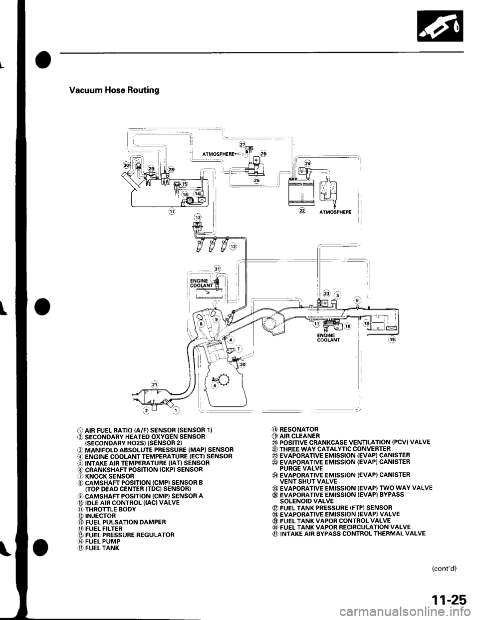
Vacuum Hose Routing
I
O AIR FUEL RATIO IA/F) SENSOR {SENSOR 1}O SECONDARY HEATED OXYGEN SENSORISECONDARY HO2S} {SENSOR 2}
O MANIFOLD ABSOLUTE PRESSURE (MAPI SENSORO ENGINE COOLANT TEMPERATURE {ECT) SENSORO INTAKE AIR TEMPERATURE (IAT) SENSORO CRANKSHAFT POSITION (CKP) SENSORO KNOCK SENSORO CAMSHAFT POSITION (CMPI SENSOR BITOP DEAD CENTER ITDC) SENSOR)
O CAMSHAFT POSITION ICMPI SENSOR A@ IDLE AIR CONTROL (IACI VALVEO THRONLE BODY.O INJECTOR@ FUEL PULSATION OAMPER[I FUEL FILTER@ FUEL PRESSURE REGULATOR@ FUEL PUMP@ FUEL TANK
@ RESONATOR(9 AIR CLEANER@ POSITIVE CRANKCASE VENTILATION {PCVI VALVE@ THREE WAY CATALYTIC CONVERTER@ EVAPORATIVE EMISSION {EVAPI CANISTER@ EVAPORATIVE EMISSION {EVAP) CANISTERPURGE VALVE{} EVAPORATIVE EMISSION (EVAPI CANISTERVENT SHUT VALVE{' EVAPORATIVE EMISSION {EVAP) TWO WAY VALVE@ EVAPORATIVE EMISSION IEVAPI BYPASSSOLENOID VALVE@ FUEL TANK PRESSURE (FTP) SENSOR@ EVAPORATIVE EMISSION IEVAP} VALVE@ FUEL TANK VAPOR CONTROL VALVE60) FUEL TANK VAPOR RECIRCULATION VALVEO INTAKE AIR BYPASS CONTROL THERMAL VALVE
(cont'd)
11-25
Page 233 of 1139
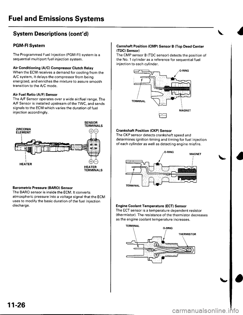
Fuel and Emissions Systems
System Descriptions (cont'd)
PGM-FI System
The Programmed Fuel Injection (PGM-Fl) system is a
sequential multiport fuel injection system.
Air Conditioning {A/C) Compressor Glutch Relay
When the ECfM receives a demand for cooling from the
Ay'C system, it delays the compressor from being
energized, and enriches the mixture to assure smooth
transition to the AVC mode.
Air Fuel Ratio lA/Fl Sensor
The Ay'F Sensor operates over a wide airlfuel range. The
Ay'F Sensor is installed upstream of the TWC, and sends
signals to the ECM which varies the duration of fuel
injection accordingly.
SENSORTERMINALS
HEATERTERMINALS
Barometric Pressure {BAROI Sensor
The BARO sensor is inside the ECM. lt convens
atmospheric pressure into a voltage signal that the ECM
uses to modify the basic duration of the fuel injection
discharge.
ztRcoNtaELEMENT
HEATER
11-26
\,
Camshaft Position (CMPI Sensor B (Top Dead Center(TDCI Sensor)
The CMP sensor B (TDC sensor) detects the position of
the No. 1 cylinder as a reference for sequential fuel
injection to each cylinder.
Crankshaft Position (CKPI Sensor
The CKP sensor detects crankshaft soeed and
determines ignition timing and timing for fuel injection
of each cylinder as well as detecting engine misfire.
Engine Coolant Temperature (ECT) Sensor
The ECT sensor is a temperature dependent resistor(thermistor). The resistance of the thermistor decreases
as the engine coolant temperature increases.
MAGNET
TERMINAL
Page 245 of 1139
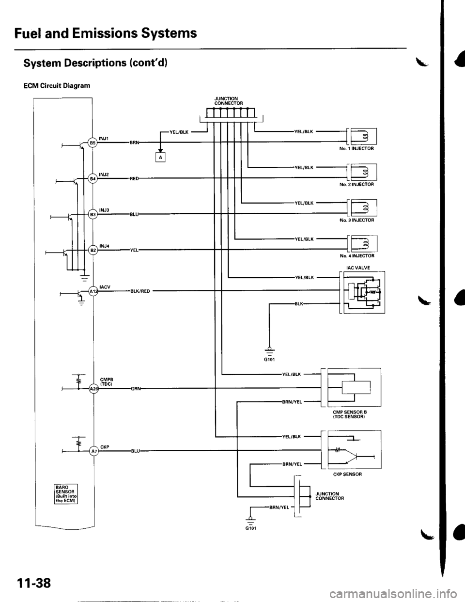
Fuel and Emissions Systems
I
a
a
System Descriptions (cont'd)
ECM Circuit Diagram
CONNECTOi
mrrrrn
CMP SENSOR B(TDC SENSOn)
I-BRN/YEr-
11-38
\,
Page 256 of 1139
![HONDA CIVIC 2002 7.G Workshop Manual PGM-FI System
Component Location Index
CAMSHAFT POS]TION {CMP) SENSOR B(TOP DEAD CENTER (TDC}SENSORITroubleshootina. oaoe 1 1-95Replacement, p;ge 1-1.1 14
ELECTRICAL LOADDETECTOR {ELDITroubleshooting, HONDA CIVIC 2002 7.G Workshop Manual PGM-FI System
Component Location Index
CAMSHAFT POS]TION {CMP) SENSOR B(TOP DEAD CENTER (TDC}SENSORITroubleshootina. oaoe 1 1-95Replacement, p;ge 1-1.1 14
ELECTRICAL LOADDETECTOR {ELDITroubleshooting,](/img/13/5744/w960_5744-255.png)
PGM-FI System
Component Location Index
CAMSHAFT POS]TION {CMP) SENSOR B(TOP DEAD CENTER (TDC}SENSORITroubleshootina. oaoe 1 1-95Replacement, p;ge 1-1.1 14
ELECTRICAL LOADDETECTOR {ELDITroubleshooting,page 1'l -92
INTAKE AIR TEMPERATURE{IATI SENSORTroubleshooting,page 'l'l-55
Replacement, page 11-'l 15
f- \
rl
KNOCK SENSORTroubleshooting, page 1 1-77Beplacement, page 11 115
ENGINE COOLANT TEMPERATURE(ECTI SENSORTroubleshooting, page 1 1-57Replacement, page 11 114
MANIFOLD ABSOLUTE PRESSURE(MAP) SENSORTroubleshooting, page 1 1-52
THROTTLE POSITIONITP} SENSORTroubleshooting, page 11-60CRANKSHAFT POSITIONICKPISENSORTroubleshooting, page'l 1-78Beplacement, page 1 1-'l 16
AIR FUEL RATIO {A/F)SENSOR ISENSOR 1}Trorrbleshooting, page 1 1-84Replacement, page 11- 1 13
{cont'd)
ii'- r'1
.I11 ---:,I''.!,i(..,.?:fir-J-
.....,..:--.
11-49