engine electrical HONDA CIVIC 2002 7.G Workshop Manual
[x] Cancel search | Manufacturer: HONDA, Model Year: 2002, Model line: CIVIC, Model: HONDA CIVIC 2002 7.GPages: 1139, PDF Size: 28.19 MB
Page 14 of 1139
ne
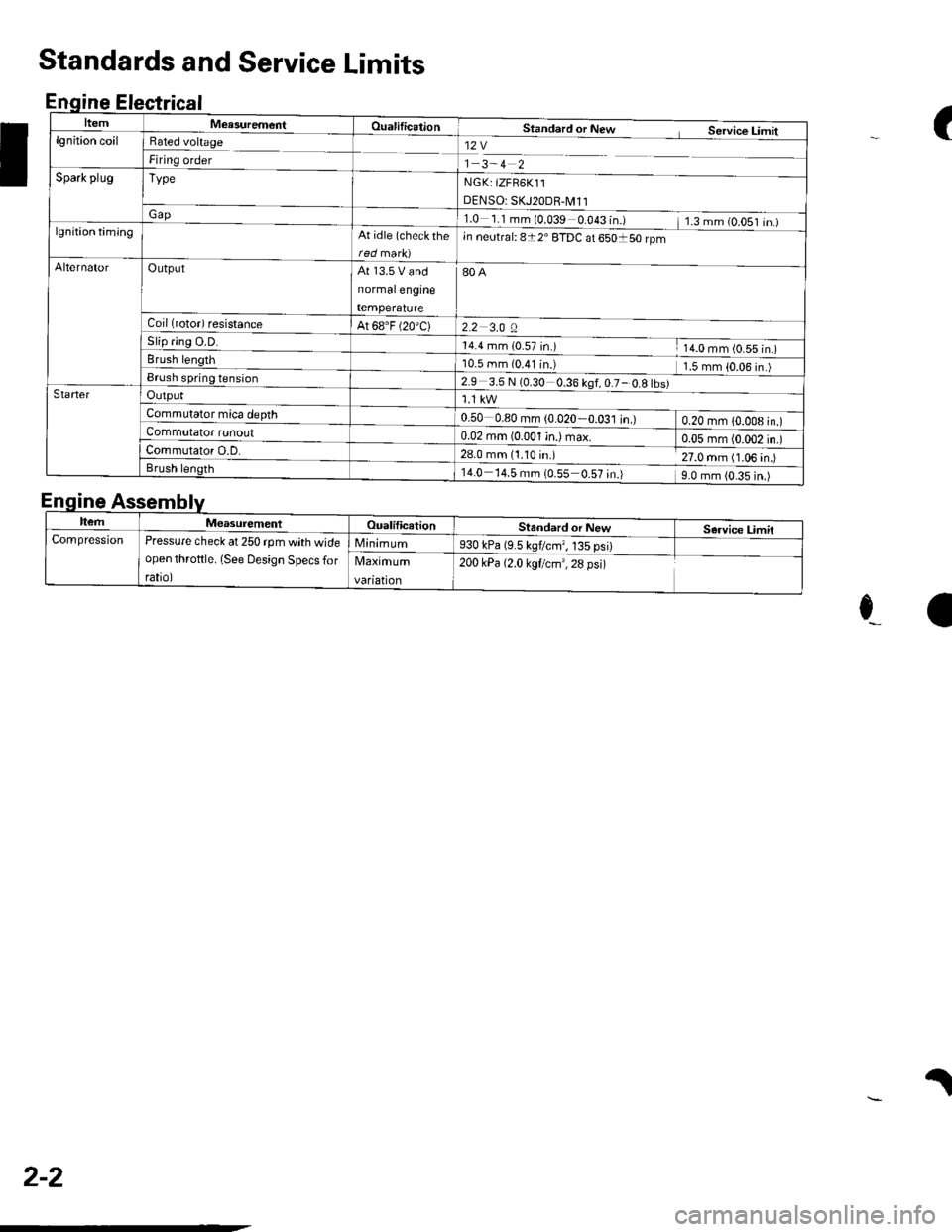
ItemMeasurementOualificationStandard or New Service Limitlgnition coilRated voltage
Firing order12V
1 3-4 2
NGK: tZFB6K11
DENSO: SKJ20DR-M11
1.0 1.1mm(0.039 0.043 in.) 1.3mm(O.OS1 in.)
Spark plugType
Gap
lgnition timingAt idle (check rhein neutral: 8t2' ETDC at 650150 rpm
AlternatorOutputAt 13.5 V and
normalengine
temperature
80A
2.2 3.0 ACoil lrotor) resistanceAt 68.F (20'C)
5|lp flng u.u.14.4 mm {0_57 in.) 14.0 mm (0.55 in.)Brush length10.5 mm (0.41 in.l 1.5 mm {0.06 in.)Brush spring tension2.9 3.5 N (0.30 0.36 kgf,0.7-0.8 tbs)StarterOutput
Commutator mica depth0.50 0.80 mm (0.020-0.031 in.) 0.20 mm 1O.OO8 in.)Commutator tunouto:BlalqryL4i) max o.o5 mm (0.002 in.)Commutator O.D.28.0 mm (1.10 in.) 27.0 mm (1.06 in.)Brush length14.0 14.5 mm {0.55 0.57 in.) 9.0 mm {0.35 in.)
(
I
Standards and Service Limits
Enqine Electrical
E
e_a
.l
nqtne
ItemMeasurementOualificationStandard or NewService LimitCompressionPressure check at 250 rpm with wide
open throftle. (See Design Specs for
rato,
Minimum930 kPa (9.5 kgflcmr, 135 psi)
Maximum
vanatton
200 kPa {2.0 kgf/cm',28 psi)
2-2
Page 36 of 1139
\.
Engine Electrical
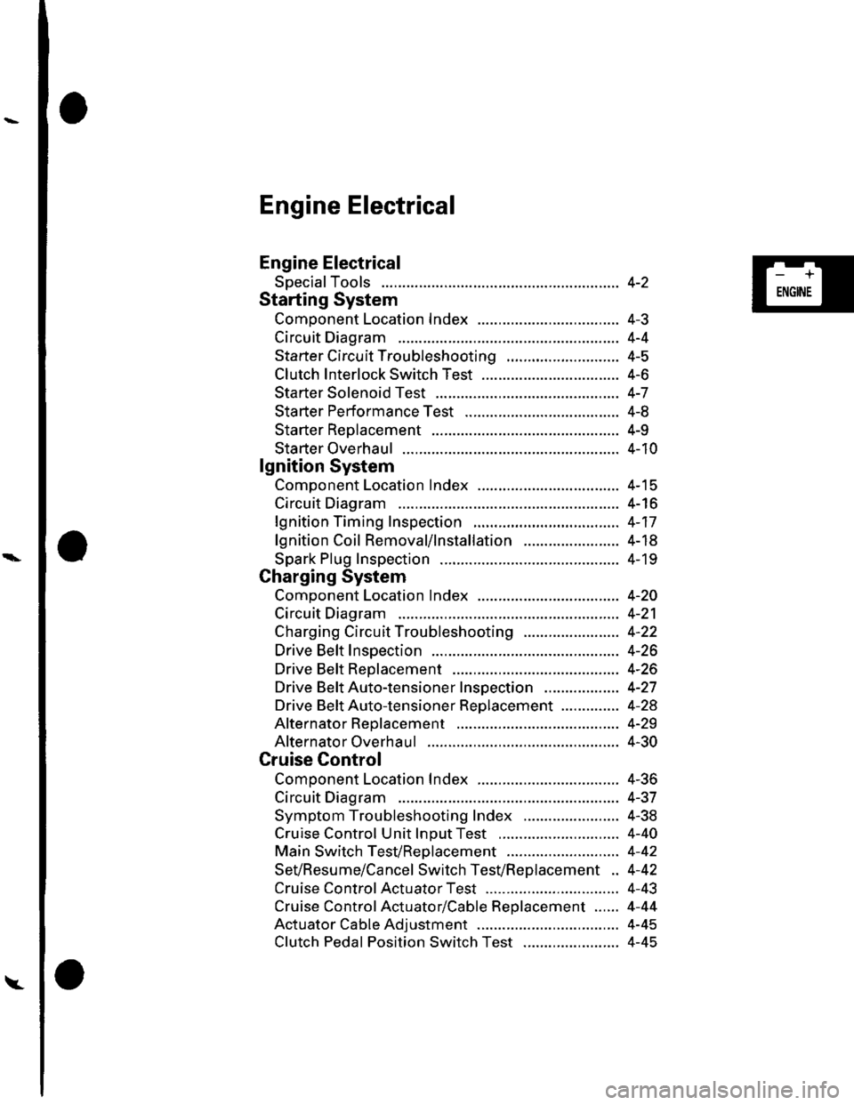
Engine Electrical
SpecialTools
Starting System
Comoonent Location Index ...............
Circuit Diagram
Starter Circu it Troubleshooting
Clutch Interlock Switch Test
Starter Solenoid Test ..............
Sta rter Performance Test
Starter Reolacement ...............
Starter Overhaul .......................
lgnition System
Component Location Index ...............
Circuit Diagram
lgnition Timing Inspection
lgnition Coil Removal/1nsta11ation .......................
Spark Plug Inspection
Charging System
Component Location Index .................................. 4-2O
Circuit Diagram ........................... 4-21
Charging Circuit Troubleshooting ....................... 4-22
Drive Belt Inspection ................... 4-26
Drive Beft Replacement .............. 4-26
Drive BeftAuto-tensioner Inspection .................. 4-27
Drive Beft Auto-tensioner Replacement .............. 4-28
Alternator Reolacement ............. 4-29
Alternator Overhaul ................ .... 4-30
Cruise Control
Component Location Index .................................. 4-36
Circuit Diagram ........................... 4-37
Symptom Troubleshooting Index ....................... 4-38
Cruise Control Unit lnDut Test ............................. 4-40
Main Switch TesVReolacement ........................... 4-42
SeVResume/Cancel Switch TesVReplacement .. 4-42
Cruise Control Actuator Test ...... 4-43
Cruise Control Actuator/Cable Replacement ...... 4-44
Actuator Cable Adjustment .................................. 4-45
Clutch Pedal Position Switch Test ....................... 4-45
4-2
4-J
4-4
4-5
4-6
4-7
4-8
4-9
4-10
4-15
4-16
4-17
4-18
4- 19
-+
ENGINE
Page 37 of 1139
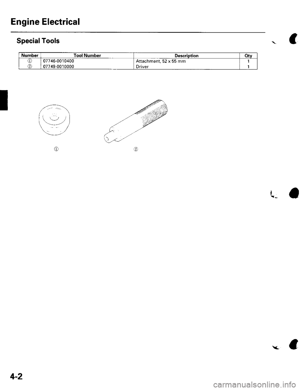
Engine Electrical
SpecialTools
I
NumberTool NumberDescriptionotv
o
@
07746-0010400
07749-0010000
Attachment, 52 x 55 mm
Driver
1
1
\C
4-2
(a
Page 40 of 1139
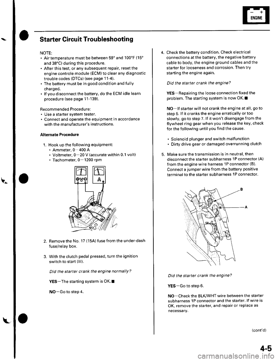
Starter Circuit Troubleshooting
NOTE:. Airtemperature must be between 59'and 100'F (15'
and 38'C) during this procedure.
. After this test, or any subsequent repair, reset the
engine controle module (ECM) to clear any diagnostlc
trouble codes (DTCS) {see page 11-4).. The battery must be in good condition and fully
charged.. lf you disconnect the baftery, do the ECM idle learn
procedure (see page 11-139).
Recommended Procedure:. Use a starter system tester.. Connect and operate the equipment in accordance
with the manuf acturer's instructions.
Alternate Procedure
1. Hook up the following equipment:. Ammeter, 0 400 A. Voltmeter, 0 20 V (accurate within 0.1 volt). Tachometer,0 1200 rpm
2.Remove the No. 17 (15A) fuse from the under-dash
fuse/relay box.
With the clutch pedal pressed, turn the ignition
switch to start (lll).
Did the starter crank the engine normally?
YES-The starting system is OK.I
NO-Go to step 4.
3.
L
4-5
4. Check the battery condition. Check electrical
connections at the battery, the negative baftery
cable to body, the engine ground cables and the
starter for looseness and corrosion. Then try
starting the engine again.
Did the statter crank the engine?
YES Repairing the loose connection fixed the
problem. The starting system is now OK.!
NO lf starterwill notcranktheengine atall, goto
step 5. lf it cranks the engine erratically or too
slowly, go to step 7. lf it won't disengage from the
flywheel ring gear when you release the key, check
for the following until you find the cause.
. Solenoid plunger and switch malfunction. Dirty drive gear or damaged overrunning clutch
5. Make sure the transmission is in neutral, then
disconnect the starter subharness 1P connector (A)
from the engine wire harness 'lP connector (B).
Connect a jumper wire from the battery positive
terminal to the starter subharness 'l P connector.
Did the starter crank the engine?
YES-Go to step 6.
NO Check the BLK,ANHT wire between the starter
subharness 1P connector and the starter. lf wire is
OK, remove the starter, and repair or replace as
necessary.
(cont'd)
Page 59 of 1139
Gharging System
Charging Circuit Troubleshooting (cont'd)
6. Start the engine. Hold the engine at 3,000 rpm with
no load (in Neutral) until the radiator fan comes on,
then let it idle.
7. Raise the engine speed to 2,000 rpm, and hold it
there.
8. Turn the headlights (high beam) on, and measure
voltage at the under-hood fuse/relay box terminal.
ls the voltage between 13.9 and 15.1 v?
YES-Go to step 9.
NO Repair or replace the alternator components
(see page 4-30).1
9. Read the amperage at '13.5 V.
NOTE: Adjust the voltage by turning the blower
motor, rear window defogger, brake lights. etc. ON.
ls the amperage 604 ot morc?
YES-Alternator/regulator operation is OK. I
NO Repair or replace the alternator components(see page 4-30).1
4-24
\,
Alternator Control System Test
NOTE: After troubleshooting, perform the engine
control module (ECM) idle learn procedure (see page
11-139).
1 . Check for proper operation of the electrical load
detector (ELD) by checking the malfunction
indicator lamp (MlL) (see page 1 l-3). lf a DTC is
present, diagnose and repair the cause before
continuing with this test.
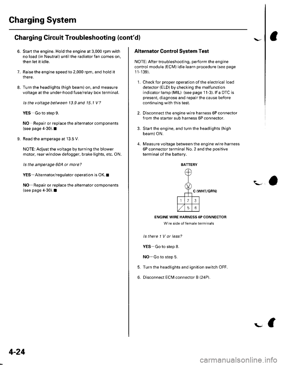
2. Disconnect the engine wire harness 6P connector
from the starter sub harness 6P connector.
3. Start the engine, and turn the headlights (high
beam) ON,
4. Measure voltage between the engine wire harness
6P connector terminal No. 2 and the positive
terminal of lhe battery.
C {WHT/GRN)
ENGINE WIRE HARNESS 6P CONNECTOR
Wire side of female terminals
ls there 1 V or less?
YES Go to step 8.
NO-Go to step 5.
Turn the headlights and ignition switch OFF.
Disconnect ECM connector B (24P).
5.
6.
BATTERY
Page 88 of 1139
Engine Assembly
Engine Removal (cont'd)
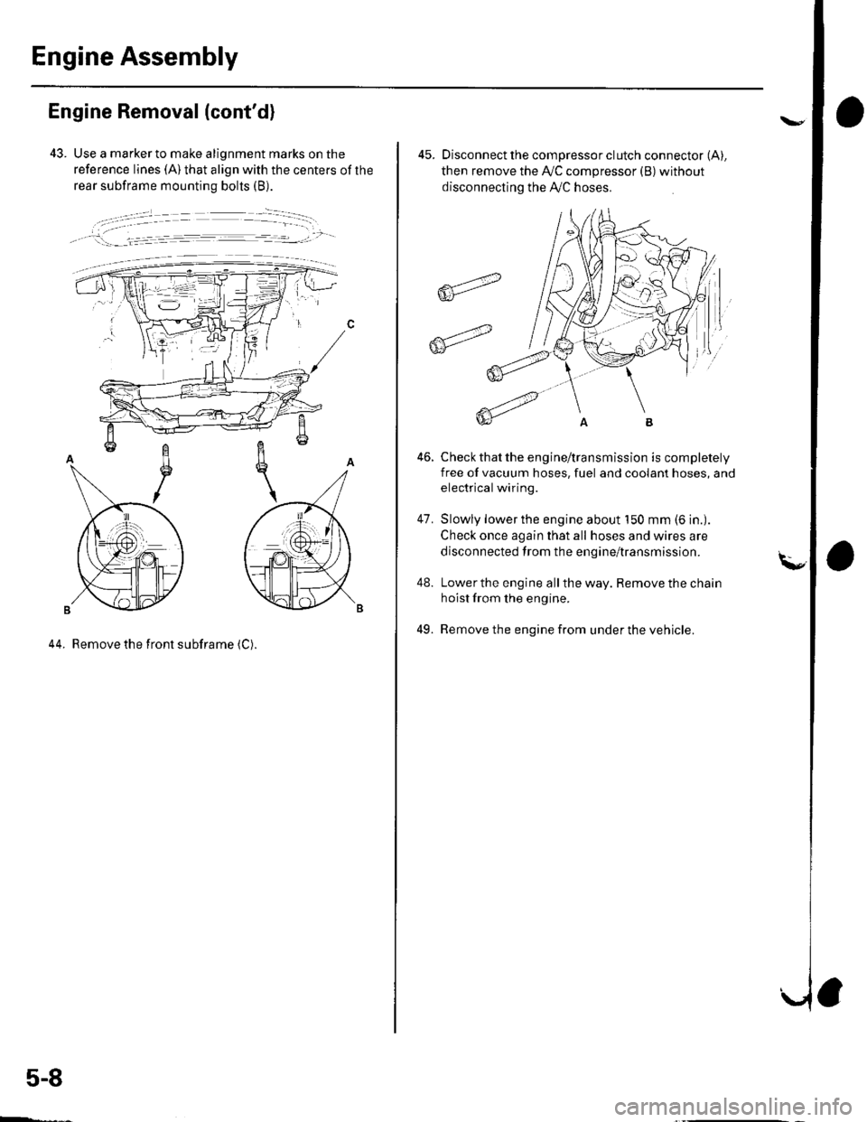
43. Use a marker to make alignment marks on the
reference lines (A) that align with the centers of the
rear subframe mounting bolts (B).
, !:_- _l.= :r -- ---.-','- -
44. Remove the front subframe (C).
5-8
ffi4
ffit'"
45. Disconnect the compressor clutch connector (A),
then remove the Ay'C compressor (B)without
disconnecting the A'./C hoses.
Check that the engine/transmission is completely
free of vacuum hoses, fuel and coolant hoses, and
electrical wiring.
Slowly lower the engine about 150 mm (6 in.).
Check once again that all hoses and wires are
disconnected trom the engine/transmission.
Lower the engine all the way. Remove the chain
hoist from the engine.
Remove the engine from under the vehicle.
46.
47.
48.
49.
Page 210 of 1139
General Troubleshooting Information
Intermittent Failures
The term "intermittent failure" means a svstem mav
have had a failure. but it checks OK now. lf the
Malfunction Indicator Lamp (MlL) on the dash does not
come on, check for Door connections or loose terminals
at all connectors related to the circuit that Vou are
troubleshooting.
Opens and Shorts
"Ooen" and "Short" are common electrical terms. An
open is a break in a wire or at a connection. A short is
an accidental connection of a wire to ground or to
another wire. In simple electronics, this usually means
something won't work at all. With complex electronics(such as ECMs)this can sometimes mean something
works, but not the way it's supposed to.
How to Use the PGM Tester or a Scan Tool
lf the MIL {Malfunction Indicator Lamp} has come on
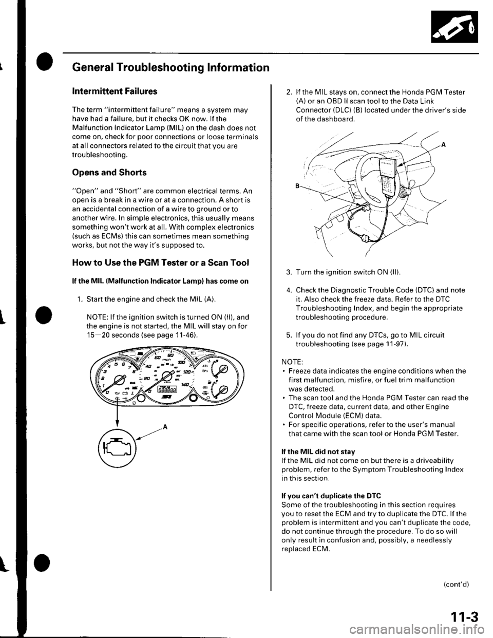
'1. Start the engine and check the MIL {A).
NOTE: lf the ignition switch is turned ON (ll), and
the engine is not started, the MIL will stay on for
15 20 seconds (see page 11-46).
K-> ;"PN/.- -::: - -d V-: !
w:ix&K#
2. lf the MIL stays on, connect the Honda PGM Tester(A) or an OBD ll scan tool to the Data Link
Connector {DLC) (B) located under the driver's side
of the dashboard.
3.
5.
Turn the ignition switch ON (ll).
Check the Diagnostic Trouble Code (DTC) and note
it. Also check the freeze data. Refer to the DTC
Troubleshooting Index, and begin the appropriate
troubleshooting procedure.
lf you do not find any DTCS, go to MIL circuit
troubleshooting (see page 11-97).
NOTE:. Freeze data indicates the engine conditions when the
first malfunction, misfire, or fuel trim malfunction
was detected.. The scan tool and the Honda PGM Tester can read the
DTC, freeze data, current data, and other Engine
Control l\4odule {EClvl) data.. For specific operations, refer to the user's manual
that came with the scan tool or Honda PG l\4 Tester.
lf the MIL did not stay
lf the MIL did not come on but there is a driveability
problem, refer to the Symptom Troubleshooting Index
in this section.
lf you can't duplicate the DTC
Some of the troubleshooting in this section requires
you to reset the ECM and try to duplicate the DTC. lf rhe
problem is intermittent and you can't duplicate the code,
do not continue through the procedure. To do so will
only result in confusion and, possibly, a needlessly
replaced ECM.
(cont'd)
11-3
Page 213 of 1139
Fuel and Emissions Systems
General Troubleshooting Information (cont'd)
ECM Updating and Substitution for Testing
Special Tools Bequired
Honda Interface Module (HlM) EOS05435570
Use this procedure when you have to substitute a
known-good ECM in a troubleshooting procedure.
U pdate the ECM only if the ECN4 does not already have
the latest software loaded,
NOTE;. lMake sure the battery is fully charged before you
update the ECN4.. To prevent ECM damage during the update, do not
turn the ignition switch OFF, and do not use any of
the vehicle's electrical devices (light, horn, radio, etc. ).
How to Update the ECM
1. Turn the ignition switch ON (ll). Do not startthe
eng Ine.
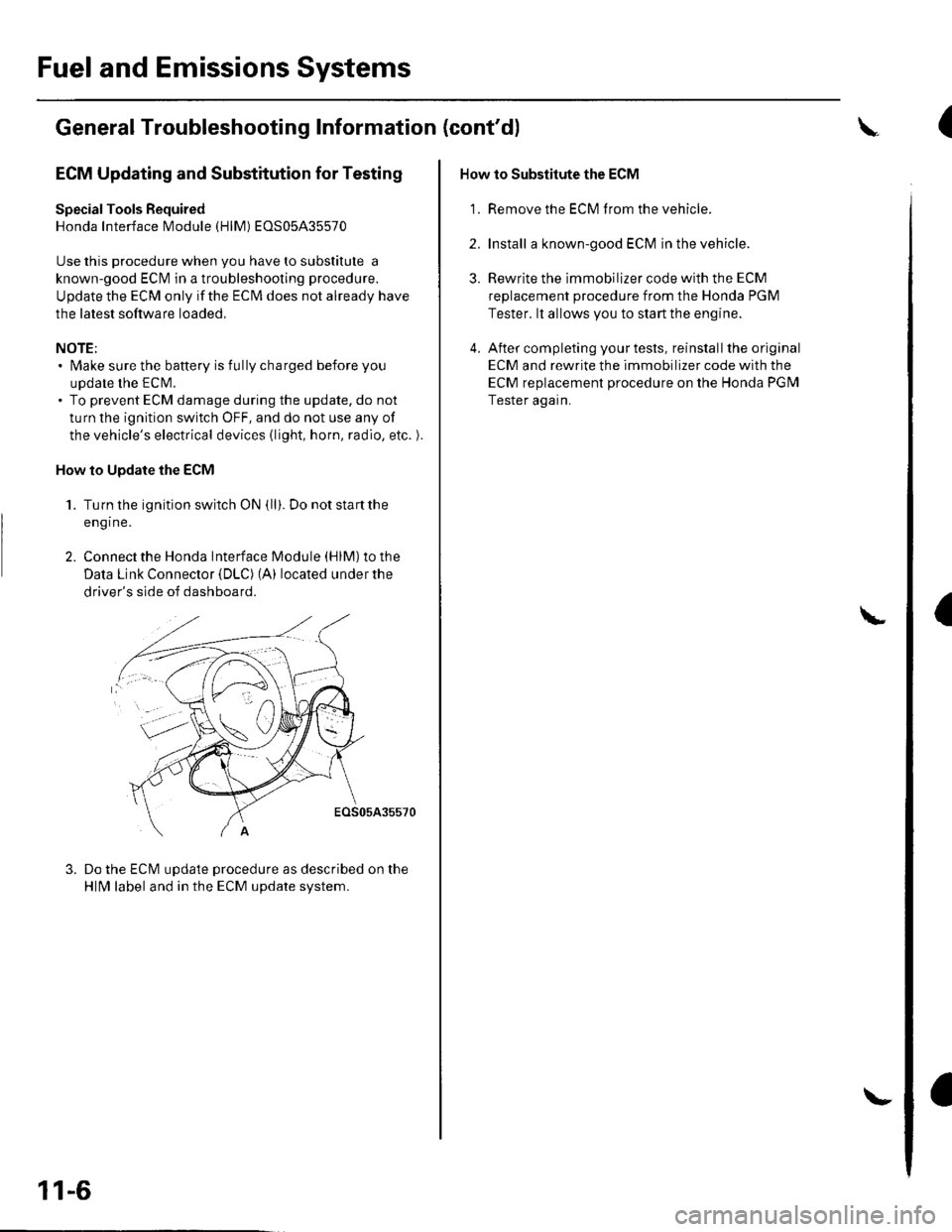
2. Connect the Honda lnterface Module (HlM) to the
Data Link Connector {DLC) (A) located under the
driver's side of dashboard.
EOS05A35570
Do the ECM update procedure as described on the
HlN4 label and in the ECM update system.
11-6
\-
How to Substitute the ECM
'1. Remove the ECM f rom the vehicle.
2. Install a known-good ECM in the vehicle.
3. Rewrite the immobilizer code with the ECM
replacement procedure from the Honda PGM
Tester. lt allows you to start the engine.
4. After completing your tests, reinstall the original
ECM and rewrite the immobilizer code with the
ECM replacement procedure on the Honda PGM
Tester again.
L
(
I
Page 216 of 1139
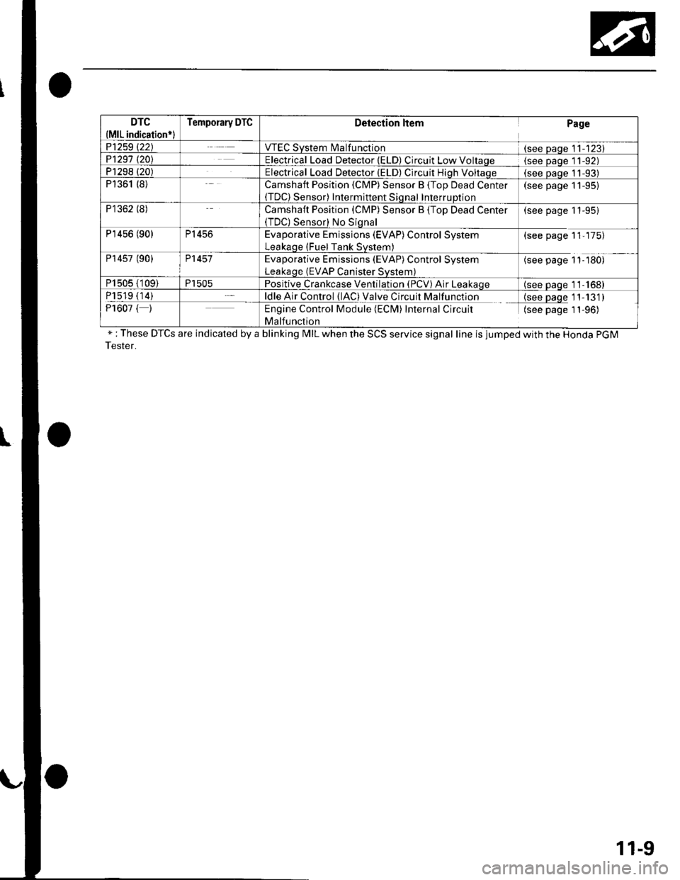
DTC
{MlL indication*l
Temporary DTCDetection ltemPage
P1259 t22JVTEC System l\4alfunction(see Daqe 11-123)P1291 t20\Electrical Load Detector (ELD) Circuit Low Voltaqe(see Daqe l1-92)P1298 (20)Electrical Load Detector (ELD) Circuit Hiqh Voltaqe(see oaoe 11-93)P1361 (8)Camshaft Position (CMP) Sensor B (Top Dead Center(TDC) Sensor) Intermittent Sional InterruDtion
(see page 11-95)
P1362 (8)Camshaft Position (CMP) Sensor B (Top Dead Center(TDC) Sensor) No Siqnal
(see page 11-95)
P'r456 (90)P1456Evaporative Emissions (EVAP) Control System
Leakaqe (Fuel Tank Svstem)
(see page 11-175)
P14s7 (90)P1457Evaporative Emissions (EVAP) Control System
Leakaqe (EVAP Canister Svstem)
(see page 1'l-180)
P1505 (109)P1505Positive Crankcase Ventilation (PCV) Air Leakaqe(see oaqe 11-1681
P1519 (14)ldle Air Control (lAC) Valve Circuit Malfunction{see paqe 11-131)P1607 ( )Engine Control Module (ECM) Internal Circuit
Malfunction
(see page 1 1-96)
" : These DTCS are indicated by a blinking MIL when the SCS service signal line is jumped with the Honda PGM
Tester.
11-9
Page 220 of 1139
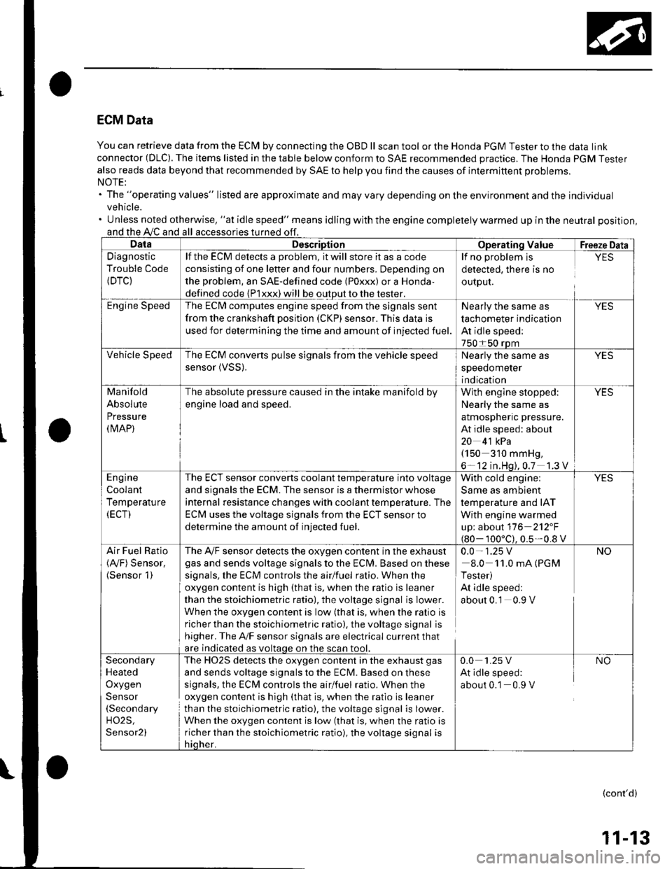
ECM Data
You can retrieve data from the ECI\4 by connecting the OBD ll scan tool or the Honda PGM Tester to the data link
connector (DLC). The items listed in the table below conform to SAE recommended practice. The Honda PGM Tester
also reads data beyond that recommended by SAE to help you find the causes of intermittent problems.
The "operating values" listed are approximate and may vary depending on the environment and the individual
vehicle.
Unless noted otherwise, "at idle speed" means idling with the engine completely warmed up in the neutral position,
and the A,/C and all
Diagnostic
Trouble Code(DTC}
lf the ECM delects a problem, it will store it as a code
consisting of one letter and four numbers. Depending on
the problem, an SAE-defined code (Poxxx) or a Honda,
defined code {P1xxx) will be output to the tester.
The ECI\4 computes engine speed from the signals sent
from the crankshaft position (CKP) sensor. This data is
used for determining the time and amount of injected fuel.
detected, there is no
ourpul.
lf no problem is YES
Nearly the same as
tachometer indication
At idle speed;
The ECM converts pulse signals from the vehicle speed
sensor (VSS).Nearly the same as
speedometer
indication
Manifold
Absolute
Pressure(MAP)
The absolute pressure caused in the intake manifold by
engine load and speed.
With engine stopped: YES
Nearly the same as
almospnenc pressure.
At idle speed: about
20 4'1 kPa(150 310 mmHg,
6- 12 in.Hq).0.7 1.3 V
The ECT sensor converts coolant temperature into voltage
and signals the ECM. The sensor is a thermistor whose
internal resistance changes with coolant tempetature. The
ECM uses the voltage signals from the ECT sensor to
determine the amount of injected fuel.
With cold engine:
Same as ambient
temperature and IAT
With engine warmed
up; about 116 2'12"F
100'c).0.5-0.8 v
Air Fuel Ratio The A,/F sensor detects the oxygen content in the exha ust 0.0 - 1 .25 V(Ay'F) Sensor. gas and sends voltage signals to the Eclvl, Basedonthese 8.0 11.0mA(PGM(Sensor 1) signals, the ECM controls the airlfuel ratio. When the I Tester)
oxygen content is high (that is, when the ratio is leaner At idle speed:
than the stoichiometric ratio), the voltage signal is Iower. about 0.1 0.9 V
When the oxygen content is low (that is, when the ralio is
richer than the stoichiometric ratio). the voltage signal is
higher. The A'lF sensor signals are electrical current that
are indicated as voltaqe on the
The HO2S detects the oxygen content in the exhaust gas
and sends voltage signals to the ECM. Based on these
signals, the ECM controls the airlfuel ratio. When the
oxygen content is high (that is, when the ratio is leaner
than the stoichiometric ratio), the voltage signal is lower.
When the oxygen content is low (that is, when the ratio is
richer than the stoichiometric ratio), the voltage signal is
Secondary
Heated
Oxygen
Sensor(Secondary
H02S,
Sensor2)
0.0 1.25 V NO
At idle speed:
about 0.1 0.9 V
(cont'd)
11-13