fuses HONDA CIVIC 2002 7.G Workshop Manual
[x] Cancel search | Manufacturer: HONDA, Model Year: 2002, Model line: CIVIC, Model: HONDA CIVIC 2002 7.GPages: 1139, PDF Size: 28.19 MB
Page 25 of 1139
t
v
2-13
o
o
a
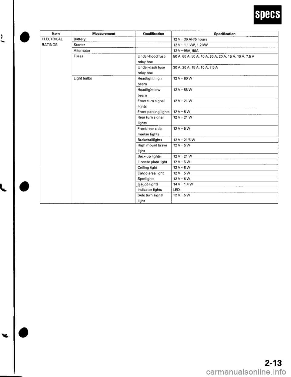
ItemMeasurementOualilicationSpecitication
ELECTRICAL
RATINGS
Battery12V 36 AH/5 hours
Sta rter12 V-.1.1 kW, 1.2 kW
Alternator12V 95A,90A
FusesUnder-hood fuse80 A, 60 A, 50 A, 40 A, 30 A, 20 A, 15 A, 10 A, 7.5 A
Under'dash Iuse30 4,20 a, 15 A, 10 A,7.5 A
Light bulbsHeadlight high
beam
'12 v.' 60 w
Headlight low
beam
12V 55W
Frontturn signal
liqhts
12V 21W
Front parlinq lights12V 5W
Bear turn signal
lights
12V " 21W
FronVrear side
marker lights
12V 5W
Brale/taillighls12V 21/5W
High moLrnt brake
light
12V 5W
Back up lights12V 21W
License plate light12V 5W
Ceiling light'12 v'.8 w
Cargo area light12V 5W
Spotlights12V 5W
Gauge lights
Indicator lightsLED
Side turn signal
light
12V 5W
Page 73 of 1139
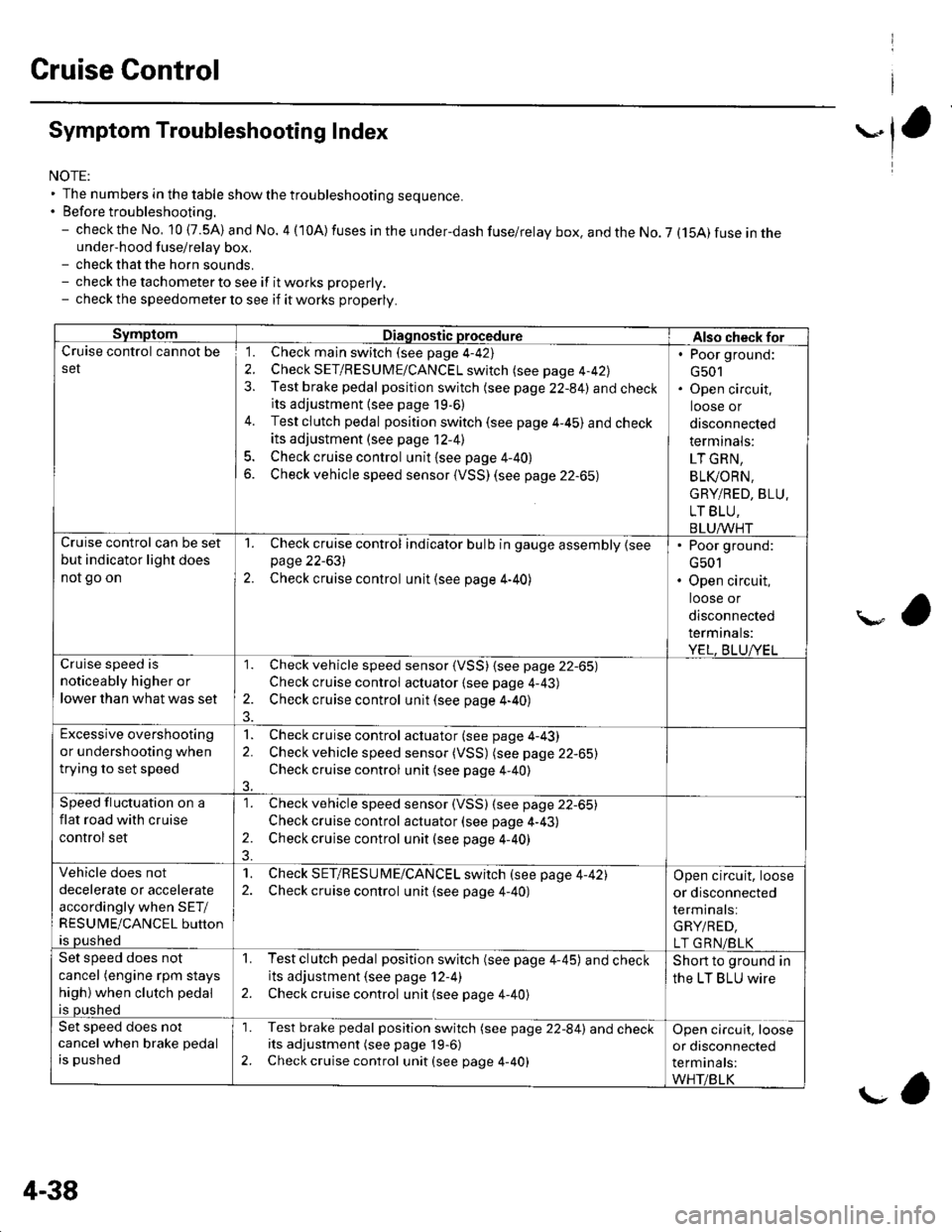
Cruise Control
Symptom Troubleshooting Index
NOTE:' The numbers in the table showthetroubleshooting sequence.. Before troubleshooting.- check the No, 10 (7.5A) and No. 4 (10A) fuses in the under-dash fuse/relay box. and the No. 7 (15A) fuse in theunder-hood fuse/relay box,- check that the horn sounds.- check the tachometer to see if it works properly.- check the speedometer lo see if it works properly.
SymptomDiagnostic procedureAlso check forCruise control cannot be
set
1. Check main switch (see page 4-42)
2. Check SET/RESUME/CANCEL switch (see page 4-42)
3. Test brake pedal position switch (see page 22-84) and checkits adjustment {see page 19,6)
4. Test clutch pedal position switch (see page 4-45) and check
its adjustment (see page 12-41
5. Check cruise control unit {see page 4-40}
6. Check vehicle speed sensor (VSS) (see page 22-65)
. Poor ground:
G501. Open circuit,
loose or
disconnected
term inals:
LT GRN,
BLI(ORN.
GRY/RED, BLU.
LT BLU,
BLUAA/HTCruise control can be set
but indicator light does
not go on
1. Check cruise control indicator bulb in gauge assembly {seepage 22-631
2. Check cruise control unit (see page 4-40)
. Poor ground:
G501. Open circuit,
loose or
disconnected
termrnats:
YEL, BLUA/ELar, 'i.a c^aa.l ic
noticeably higher or
lower than what was set
1. Check vehicle speed sensor (VSS) {see page 22-65)
Check cruise control actuator {see page 4-43)
2. Check cruise control unit (see page 4-40)
Excessive overshooting
or undershooting when
trying to set speed
1. Check cruise control actuator (see page 4-43)
2. Check vehicle speed sensor (VSS) (see page 22-65)
Check cruise control unit (see page 4-40)
3.
Speed fluctuation on a
flat road with cruise
control set
1. Check vehicle speed sensor (VSS) (see page 22-65)
Check cruise control actuator (see page 4-43)
2. Check cruise control unit (see page 4-40)
Vehicle does not
decelerate or accelerate
accordingly when SET/
RESUME/CANCEL button
is pushed
1. Check SET/RESU ME/CANCEL switch (see page 4-42)2. Check cruise control unit {see page 4-40)
Open circuit, loose
or disconnected
terminals:
GRY/RED,
LT GRN/BLKSet speed does not
cancel (engine rpm stays
high) when clutch pedal
is pushed
1. Testclutch pedal position switch (see page 4-45) and checkits adjustment (see page 12-4)
2. Check cruise control unit (see page 4-40)
Short to ground in
the LT BLU wire
Set speed does not
cancel when brake pedal
is pushed
'1. Test brake pedal position switch (see page 22-84) and checkits adjustment (see page 19-6)
2. Check cruise control unit (see page 4-40)
Open circuit, loose
or disconnected
terminals:
WHT/BLK
4-38
g,
Page 202 of 1139
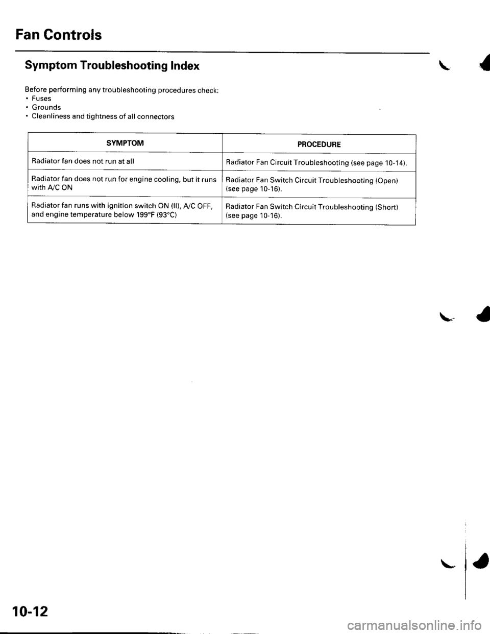
Fan Controls
Symptom Troubleshooting Index
Before performing any troubleshooting procedures check:. Fuses. Grounds. Cleanliness and tightness of all connectors
\{
\,4
SYMPTOMPROCEDURE
Radiator fan does not run at allRadiator Fan Circuil Troubleshooting (see page 1O-14).
Radiator fan does not run for engine cooling, but it runswith A,/C ON
Radiator Fan Switch Circuit Troubleshooting (Open)
(see page 10-16).
Radiator fan runs with ignition switch ON (ll), Ay'C OFF,
and engine temperature below 199"F (93"C)Radiator Fan Switch Circuit Troubleshooting (Short)
(see page 10-'16).
10-12
\-
Page 296 of 1139
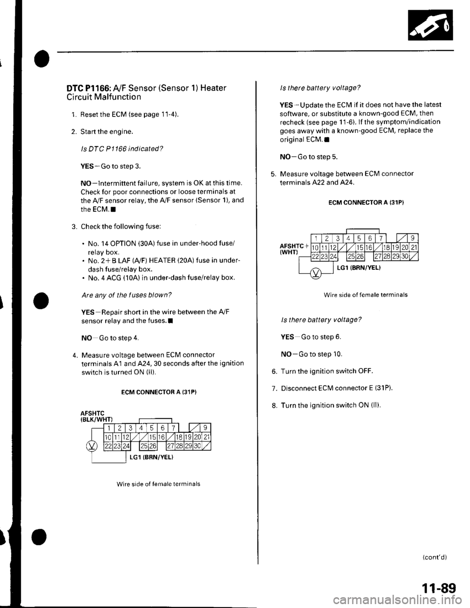
DTC Pl166: Ay'F Sensor (Sensor 1) Heater
Circuit Malfunction
1. Resetthe ECM (see page 11-4).
2. Start the engine.
ls DTC P1166 indicated?
YES-Go to step 3.
NO-lntermittent failure, system is OK at this lime.
Check for poor connections or loose terminals at
the Ay'F sensor relay, the A,/F sensor (Sensor 1), and
the EcM. !
3. Check the following fuse:
. No. 14 OPTION (30A)fuse in under-hood fuse/
reray Dox.. No. 2*B LAF (Ay'F) HEATER (20A) fuse in under-
dash fuse/relay box.. No. 4 ACG (10A) in underdash fuse/relay box.
Are any of the fuses blown?
YES Repair short in the wire between the Ay'F
sensor relay and the fuses.I
NO Go to step 4.
4. Measure voltage between ECM connector
terminals A1 and A24. 30 seconds after the ignition
switch is turned ON (ll).
ECM CONNECTOR A I31P)
Wire srde of lemale terminals
Is therc battery voltage?
YES-Update the ECM if it does not have the latest
soflware, or substitute a known-good ECM. then
recheck (see page 1 1-6). lf the symptom/indication
goes away with a known-good ECM, replace the
original ECM.I
NO-Go to step 5.
5. Measure voltage between ECM connector
terminals A22 and A24.
ECM CONNECTOR A {31P}
Wire side of female terminals
ls there battery voltage?
YES Go to step 6.
NO-Go to step 10.
6. Turn the ignition switch OFF.
7. Disconnect ECM connector E (31P).
8. Turn the ignition switch ON {ll).
(cont'd)
11-89
Page 297 of 1139
PGM-FI System
DTC Troubleshooting (cont'dl
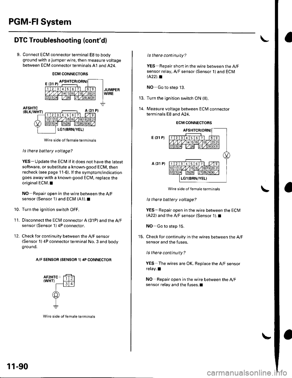
9. Connect ECM connector terminal EStobodyground with a jumper wire, then measure voltage
between ECM connector terminals A1 and 424.
ECM CONNECTORS
Wire side of female terminals
ls there battery voltage?
YES- Update the ECM if it does not have the latest
soflware, or substitute a known-good ECM, then
recheck (see page 1 1-6). lf the symptom/indication
goes away with a known-good ECM, replace the
original ECM. t
NO Repair open in the wire between the Ay'F
sensor (Sensor 1) and ECM (A1). t
Turn the ignition switch OFF.
Disconnecl the ECfM connector A (31P) and the Ay'F
sensor (Sensor 1) 4P connector.
Check for continuity between the Ay'F sensor(Sensor 1) 4P connector terminal No. 3 and bodyground.
A/F SENSOR (SENSOR 1) 4P CONNECTOR
10.
11.
12.
11-90
Wire side ot Iemale terminals
t5.
14.
ls there continuity?
YES Repair short in the wire between the A|/F
sensor relay, A,/F sensor {Sensor 1) and ECM
lA22J.a
NO Go to step 13.
Turn the ignition switch ON (ll).
Measure voltage between ECM connector
terminals E8 and A24.
ECM CONNECTORS
E {31 P)
a {31 P)
Wire side of female terminals
ls there battety voltage?
YES-Repair open in the wire between the ECM(A22) and the IVF sensor (Sensor 1). I
NO-Go to step 15.
Check for continuity in the wires between the Ay'F
sensor and the fuses.
ls there continuity?
YES-The wires are OK. Replace the A,/F sensor
relay.l
NO Repair open in the wire between the Ay'F
sensor relay and the fuses.l
Page 800 of 1139
9.
10.
Disconnect the condenser fan 2P connector,
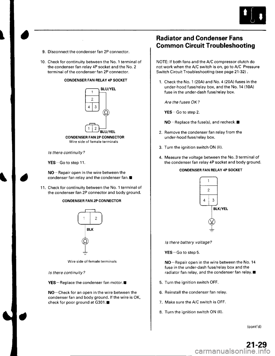
Check for continuity between the No. 1 terminal of
the condenser fan relay 4P socket and the No. 2
terminal of the condenser fan 2P connector.
CONDENSER FAN RELAY 4P SOCKET
CONDENSER FAN 2P CONNECTORWire side of female terminals
Is there continuity?
YES Go to step 1 1.
NO- Repair open in the wire between the
condenser fan relay and the condenser fan,I
Check for continuity between the No. 1 terminal of
the condenser fan 2P connector and body ground.
CONDENSER FAN 2P CONNECTOR
12
BLK
o
Wire side of {emale terminals
ls there continuity?
YES- Replace the condenser fan motor.I
NO Check for an open in the wire between the
condenser fan and body ground. lf the wire is oK,
check for poor ground at G301.1
'11 .
Radiator and Condenser Fans
Common Circuit Troubleshooting
NOTE; lf both fans and the Ay'C compressor clutch do
not work when the Ay'C switch is on, go to Ay'C Pressure
Switch Circuit Troubleshooting (see page 21-32l, .
1. Check the No. 1 {20A} and No. 4 (20A) fuses in the
under-hood fuse/relay box, and the No. 14 (10A)
fuse in the under-dash fuse/relay box.
Are the tuses OK?
YES Go to steD 2.
NO Replace the fuse(s), and recheck.l
2. Remove the condenser fan relav from the
under-hood f use/relay box.
3. Turn the ignition switch ON (ll;.
4. Measure the voltage between the No. 3 terminal of
the condenser fan relay 4P socket and body ground.
ls there battery voltage?
YES Go to step 5.
NO Repair open in the wire between the No. 14
fuse in the under-dash fuse/relay box and the
radiator fan relay, and the condenser fan relay.l
5. Turn the ignition switch OFF.
6. Reinstall the condenser fan relay.
7. Make sure the IVC switch is OFF.
8. Turn the ignition switch ON (ll).
(cont'd)
CONDENSER FAN RELAY 4P SOCKET
r-,
-l
12lf---r---
l,l,l
lar-vver-
l
o
I
21-29
Page 834 of 1139
General Troubleshooting Information
Tips and Precautions
Bef ore Troubleshooting
1. Check applicable fuses in the appropriate fuse/relay
oox.
2. Check the battery for damage. state of charge, and
clean and tight connections.
. Do not quick-charge a battery unless the battery
ground cable has been disconnected, otherwise
you will damage the alternator diodes.. Do not attempt to crank the engine with the
battery ground cable loosely connected or you
will severely damage the wiring.
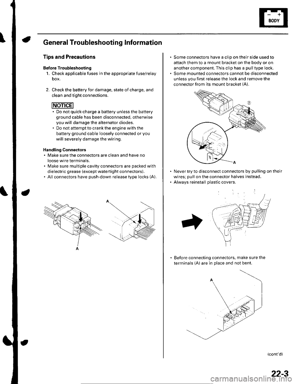
Handling Connectors. Make sure the connectors are clean and have no
loose wire terminals.. Make sure multiple cavity connectors are packed with
dielectric grease (except waterti ght connectors).. All connectors have push-down release type locks (A).
Some connectors have a clip on their side used to
attach them to a mount bracket on the body or on
another component. This clip has a pull type lock.
Some mounted connectors cannot be disconnected
unless you first release the lock and remove the
connector from its mount bracket (A).
Never try to disconnect connectors by pulling on their
wires; pull on the connector halves instead.
Alwavs reinstall Dlastic covers,
Before connecting connectors, make sure the
terminals (A) are in place and not bent.
(cont'd)
22-3
Page 877 of 1139
Power Distribution
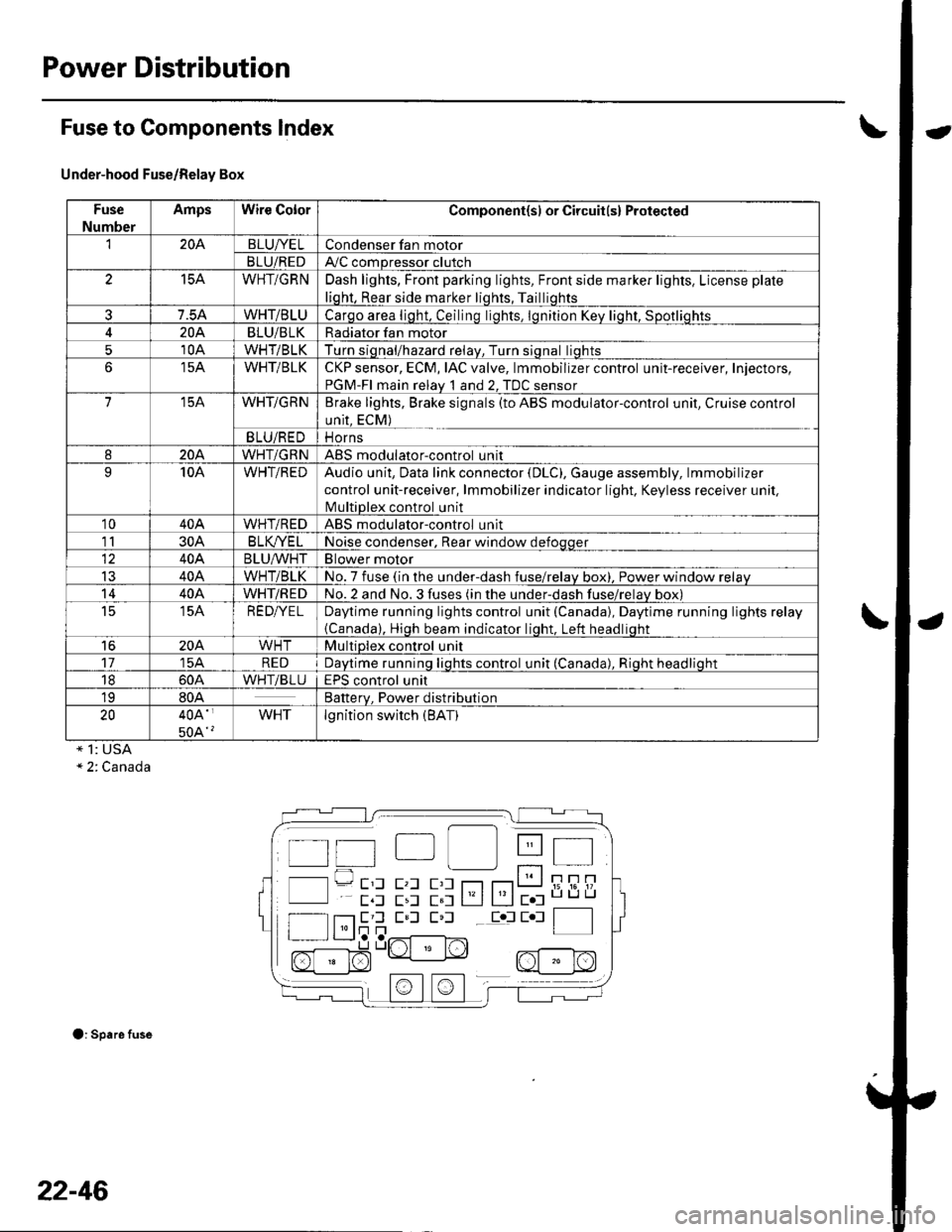
Fuse to Components lndex
Under-hood Fuse/Relay Box
Fuse
Number
AmpsWire ColorComponent(sl or Circuit(s) Protected
'I204BLUI/ELCondenser fan motor
BLU/REDAy'C compressor clutch
15AWHT/GRNDash lights, Front parking lights, Front side marker lights, License plate
liqht, Rear side marker liqhts, Tailliqhts
7.5AWHT/BLUCarqo area liqht, Ceilinq liqhts. lqnition Kev liqht. Sootliohts
204BLU/BLKRadiator fan motor
510AWHT/BLKTurn siqnal/hazard relav, Turn siqnal liqhts
15AWHT/BLKCKP sensor, ECM, IAC valve, lmmobilizer control unit-receiver, Injectors,
PGM-FI main relav 1 and 2. TDC sensor
715AWHT/GRNBrake lights, Brake signals (to ABS modulator-control unit, Cruise control
unit, ECM)
BLU/REDi1 Orns
820AWHT/GRNABS modulatorcontrol unit
910AWHT/REDAudio unit, Data link connector (DLC), Gauge assembly, lmmobilizer
control unit-receiver, lmmobilizer indicator light. Keyless receiver unil,
lvlultiDlex control unit
1040AWHT/REDABS modulator-control unit
1130AB LK/YE LNoise condenser, Rear window defoqqer
40ABLU^^/HTBlower motor
IJ40AWHT/BLKNo. 7 fuse (in the under-dash fuse/relav box), Power window relav
1440AWHT/REDNo.2 and No.3 fuses (in the under-dash fuse/relav box)
t515AREDI/ELDaytime running lights control unit (Canada), Daytime running lights relay
{Canada), Hioh beam indicator liqht. Left headliqht
16204WHTMultiplex control unit
1715AREDDavtime runninq liqhts control unit (Canada). Rioht headlioht
1860AWHTiBLUEPS control unit
1980ABatterv. Power distribution
2040A'
50A'?
WHTlgnition switch (BAT)
* 1: USA" 2. Canada
O: Spare fuse
t t"| lll Itt 4t I
l l---- E'l E,l E,l r--r r---r t__J i; i6'!/'
E,l E,l E,l Eol E l f__--lI l'lr]n | |I r L__J,a ,..r^{-------l^-,
n[:]$"Lrt " N2, nf - r^l
22-46
Page 896 of 1139
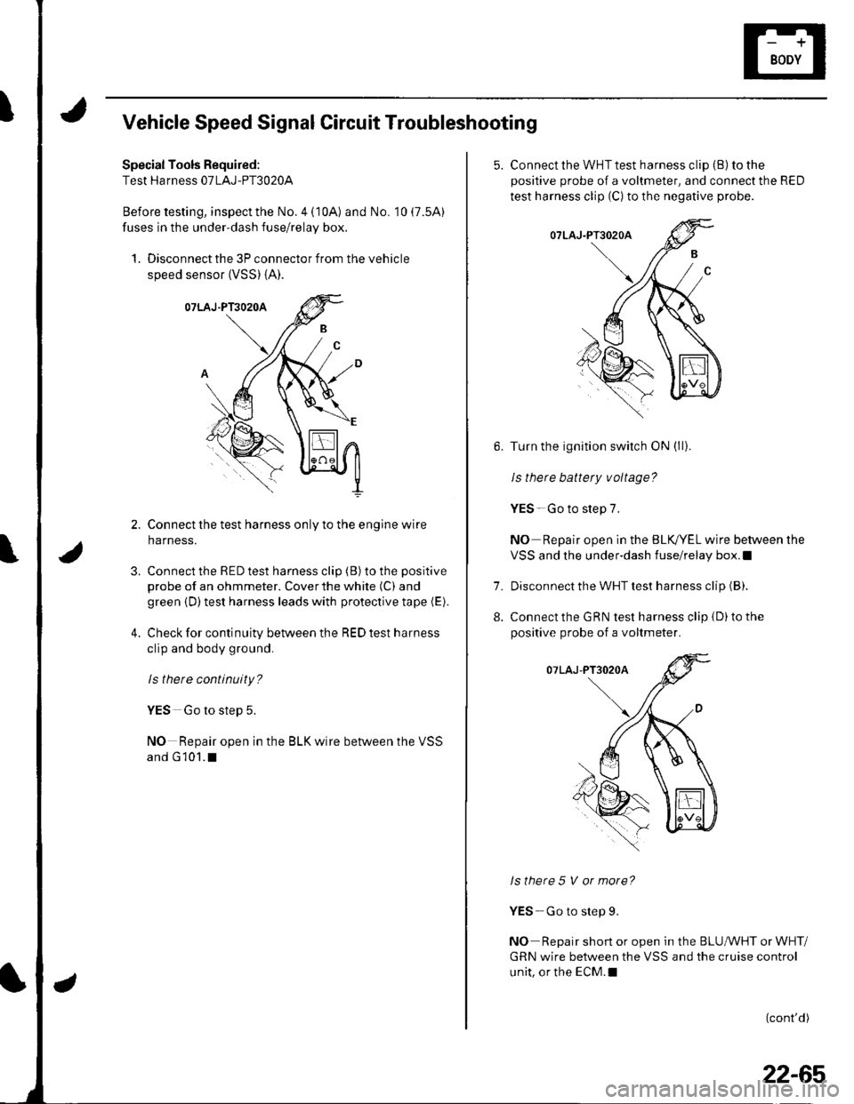
IVehicle Speed Signal Circuit Troubleshooting
Special Tools Required:
Test Harness 07LAJ-PT3020A
Before testing, inspect the No. 4 (10A) and No. 10 (7.5A)
fuses in the under-dash fuse/relay box.
1. Disconnect the 3P connector from the vehicle
speed sensor (VSS) {A).
Connect the test harness only to the engine wire
harness.
Connect the RED test harness clip (B) to the positive
probe of an ohmmeter. Cover the white (C) and
green {D) test harness leads with protective tape (E).
Check for continuity between the RED test harness
clip and body ground,
ls there continuity?
YES Go to step 5.
NO Repair open in the BLK wire between the VSS
and G 101.I
3.
4.
5. Connect the WHT test harness cliD (B) to the
positive probe of a voltmeter, and connect the RED
test harness clip (C) to the negative probe.
Turn the ignition switch ON (ll).
le thara h2ltarv v^ltada?
YES-Go to step 7.
NO Repair open in the BLK,/YEL wire between the
VSS and the under-dash fuse/relay box.l
Disconnect the WHT test harness clip (B).
Connect the GRN test harness clip {D) to the
positive probe of a voltmeter.
Is there 5 V or more?
YES- Go to step 9.
NO Repair short or open in the BLUMHT or WHT/
GRN wire between the VSS and the cruise control
unit, or the ECM.I
(cont'd)
7.
8.
22-65
Page 1003 of 1139
Multiplex Control System
Troubleshooting
Mode 1 Tset
1. Remove the driver's dashboard lower cover {see
page 20-59).
2. Check the No. 9 ( 10A) fuse in the under-hood fuse/
relay box and the No. 10 (7.5A) fuse in the under-
dash fuse/relay box.
Are the fuses OK?
YES-Go to step 2.
NO-Find and repairthe cause ofthe blown fuse.!
3. Turn the ignition switch ON (ll).lf the driver's
seatbelt is unbuckled the seat belt reminder will
chime 6 times.
4. Set the ceiling light to the center position and close
allthe doors.
5. Connect the specialtoolto the multiplex inspection
conneclor.
6. After about 5 seconds the spotlight and ceiling light
should come on for 2 seconds, go out, then blink on
for 0.2 second to show the system is now in mode
1.
Did the spotlight and ceiling light indicate mode
1?
YES-Go to step 8.
NO Go to step 7.
22-172
-
7. Check for continuity between terminal 4ofthe
under-dash fuse/relay box connector J and body
ground.
ls there continuity?
YES Replace the under-dash fuse/relay box.l
NO - Repair the open in the wire.lf the wire is ok,
repair G301.1
8. lf ther are any DTCS present, the spotlight and
ceiling light will blink to indicate the DTC(S). lf more
than one DTC is present, the DTCS will be displayed
in ascending order, lf there are no DTCS the
spotlight and ceiling light will not blink again after
the mode 1 indication.
Are there any DTCg?
YES Go to step 9.
NO Go to the Mode 2 test.
9. Troubleshoot the DTC(S) in the order indicated
using the following charts.
lf a faulty control unit is suspected, substitute it
with a known food part and recheck for DTCS,
. lf the DTC(s) isstill present. go to the next step
listed for the DTC.. lf the DTC(S) is no longer present replace the
original part.