performance test HONDA CIVIC 2002 7.G Workshop Manual
[x] Cancel search | Manufacturer: HONDA, Model Year: 2002, Model line: CIVIC, Model: HONDA CIVIC 2002 7.GPages: 1139, PDF Size: 28.19 MB
Page 36 of 1139
\.
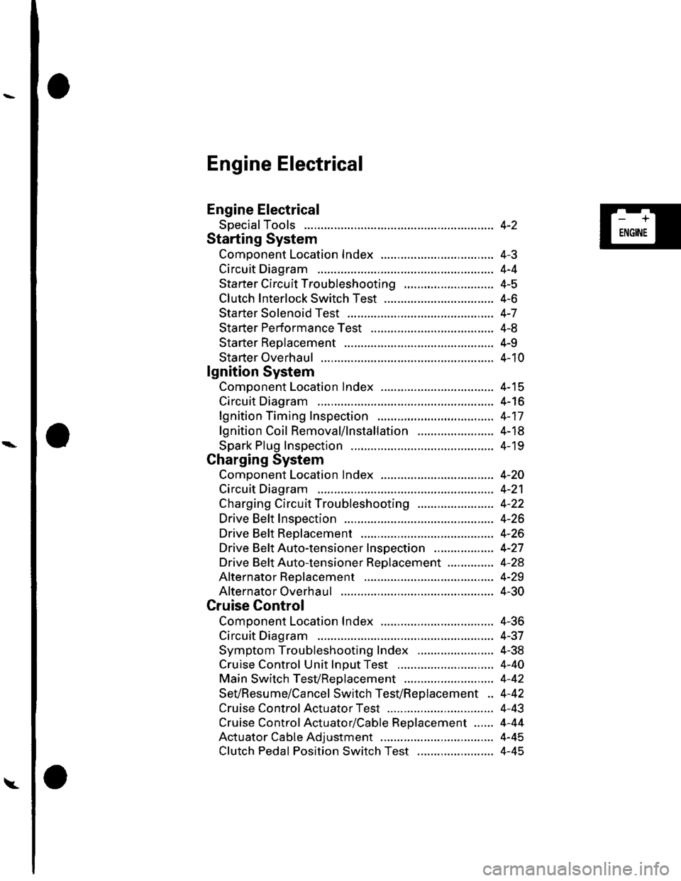
Engine Electrical
Engine Electrical
SpecialTools
Starting System
Comoonent Location Index ...............
Circuit Diagram
Starter Circu it Troubleshooting
Clutch Interlock Switch Test
Starter Solenoid Test ..............
Sta rter Performance Test
Starter Reolacement ...............
Starter Overhaul .......................
lgnition System
Component Location Index ...............
Circuit Diagram
lgnition Timing Inspection
lgnition Coil Removal/1nsta11ation .......................
Spark Plug Inspection
Charging System
Component Location Index .................................. 4-2O
Circuit Diagram ........................... 4-21
Charging Circuit Troubleshooting ....................... 4-22
Drive Belt Inspection ................... 4-26
Drive Beft Replacement .............. 4-26
Drive BeftAuto-tensioner Inspection .................. 4-27
Drive Beft Auto-tensioner Replacement .............. 4-28
Alternator Reolacement ............. 4-29
Alternator Overhaul ................ .... 4-30
Cruise Control
Component Location Index .................................. 4-36
Circuit Diagram ........................... 4-37
Symptom Troubleshooting Index ....................... 4-38
Cruise Control Unit lnDut Test ............................. 4-40
Main Switch TesVReolacement ........................... 4-42
SeVResume/Cancel Switch TesVReplacement .. 4-42
Cruise Control Actuator Test ...... 4-43
Cruise Control Actuator/Cable Replacement ...... 4-44
Actuator Cable Adjustment .................................. 4-45
Clutch Pedal Position Switch Test ....................... 4-45
4-2
4-J
4-4
4-5
4-6
4-7
4-8
4-9
4-10
4-15
4-16
4-17
4-18
4- 19
-+
ENGINE
Page 38 of 1139

\-
Starting System
Component Location Index
UNDER-DASHFUSE/RELAY BOX
CLUTCH INTERLOCK SWITCHTest, page 4-6
STARTERStaner Circuit Troubleshoot,ng, page 4 5Solenoid Test, page 4-7Performance Test, page 4-8Replacement, page 4-9Overhaul, page 4 '10
-l--
ar]]]ll -i I
-. -_- rt_.1
_-- _. /
Itti:
:-lt.i tit-!t:!|- -!t
STARTER CUT RELAYTest, page 22-51
\'l
\'\l I
r\, l,
,. /
\/'....",r.v
\:,...)
/'\tl \
4-3
Page 43 of 1139
Starting System
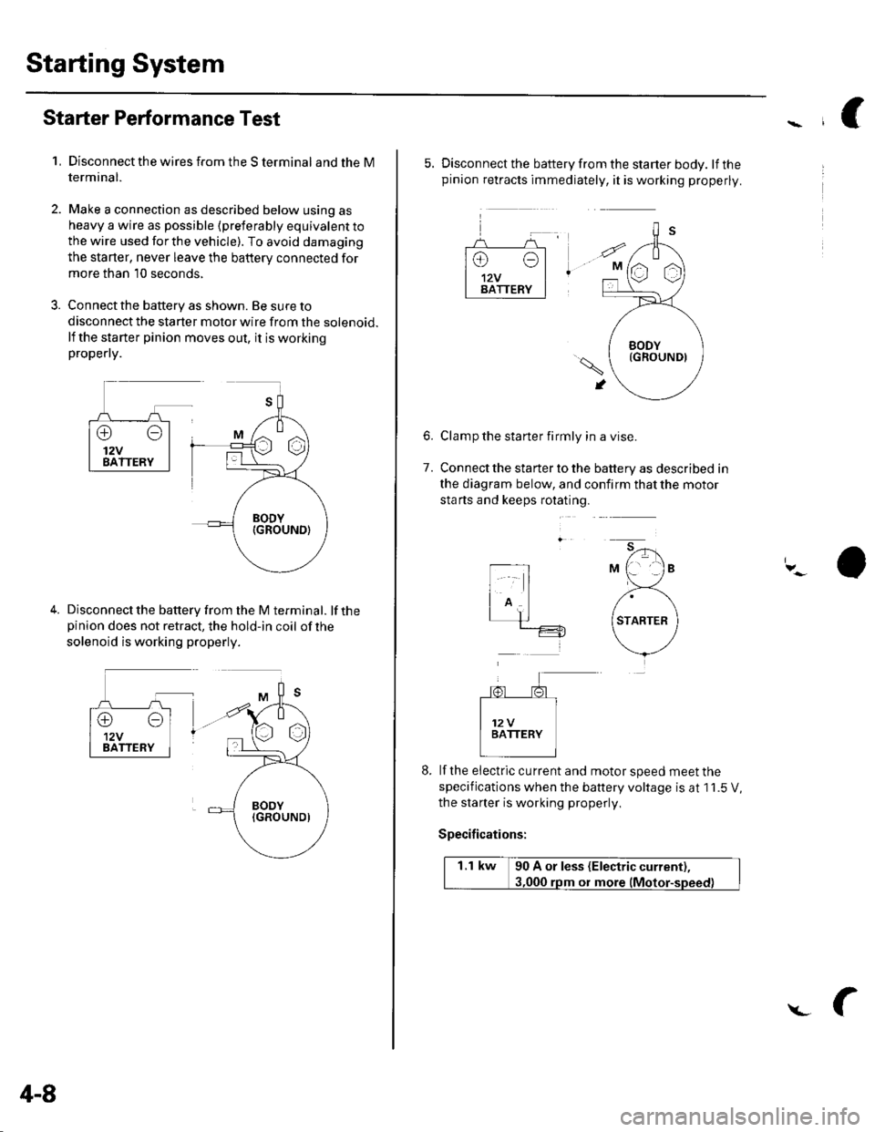
Starter Performance Test
1,Disconnect the wires from the S terminal and the M
termrnal.
Make a connection as described below using as
heavy a wire as possible (preterably equivalent to
the wire used for the vehicle). To avoid damaging
the starter, never leave the battery connected for
more than 10 seconds,
Connect the battery as shown. Be sure to
disconnect the starter motor wire from the solenoid.
lf the starter pinion moves out, it is workingpropefly.
Disconnect the battery from the M terminal. lf thepinion does not retract, the hold-in coil of the
solenoid is working properly.
4-8
L
5. Disconnect the battery from the starter body. lfthepinion retracts immediately, it is working properly.
Clamp the starter firmly in a vise.
Connect the starter to the battery as described in
the diagram below, and confirm that the motor
sta rts and keeps rotating.
6.
7.
lf the eiectric cu rrent and motor speed meet the
specifications when the battery voltage is at 1 1.5 V,
the staner is working properly,
Specifications:
1.1 kw 90 A or less (Electric current),
ot more
Page 214 of 1139
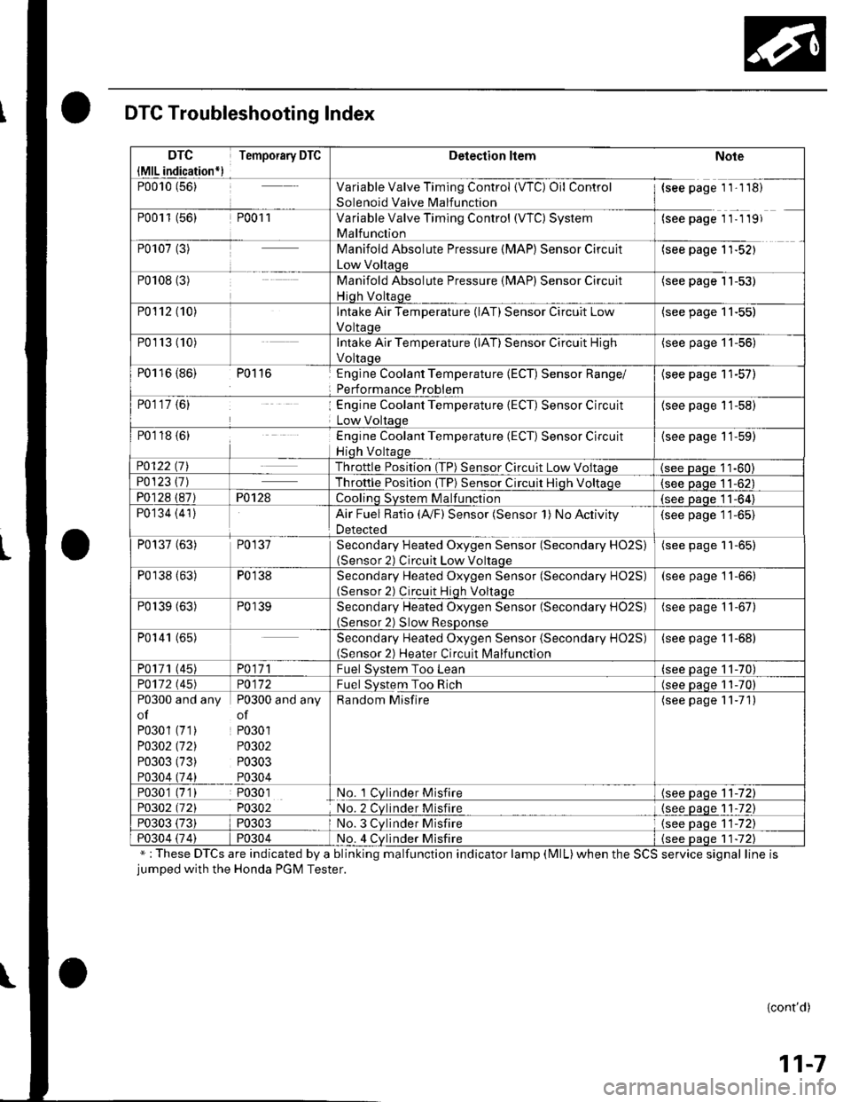
DTC Troubleshooting Index
";These DTCs are indicated by a blinking malfunction indicator lamp (MlL)when the SCS service signal line isjumped with the Honda PGM Tester.
{cont'd)
11-7
DTC
{MlL indication*)
Temporary DTCDetection ltemNote
P0010 (56)Variable Valve Timing Control {VTC) Oil Control
Solenoid Valve Malfunction
{see page 1 1'1 18)
P0011 (56)P001 1Variable Valve Timing Control (WC) System
Malfunction
(see page 11- 1 19)
P0107 (3)Manifold Absolute Pressure (MAP) Sensor Circuit
Low Voltaqe
(see page 1'l-521
P0108 (3)Manifold Absolute Pressure (MAP) Sensor Circuit
Hiqh Voltaqe
(see page 11-53)
P0112 (10)Intake Air Temperature (lAT) Sensor Circuit Low
Voltaoe
(see page 11-55)
P01r3 (10)Intake Air Temperature (lAT) Sensor Circuit High
Voltaoe
(see page '11-56)
P0116 {86) P0116Englne Coolant Temperature (ECT) Sensor Range/
Performance Problem
{see page 11-57)
P0117 {6)Engine Coolant Temperature (ECT) Sensor Circuit
Low Voltaqe
(see page 11-58)
P0118 {6)Engine Coolant Temperature (ECT) Sensor Circuit
Hiqh Voltaqe
{see page 11-59)
P0122 t7\Throttle Position (TP) Sensor Circuit Low Voltaqe(see Daqe 11-60)P0123 {7)Throttle Posltion (TP) Sensor Circuit Hiqh Voltaoe(see paqe 11-62)
P0128 (87)P0128Coolinq SVStem Malfunction(see Daqe 11-64)
P0134 (41)Air Fuel Ratio (Ay'F) Sensor (Sensor 1) No Activity
Detected
(see page 11-65)
P0137 (63)P0137Secondary Heated Oxygen Sensor (Secondary HO2S)(Sensor 2) Circuit Low Voltaqe
(see page 11-65)
P0138 (63)P0138Secondary Heated Oxygen Sensor (Secondary HO2S)(Sensor 2) Circuit Hiqh Voltaqe
(see page 11-66)
P0139 (63)P0139Secondary Heated Oxygen Sensor (Secondary H02S)(Sensor 2) Slow ResDonse
(see page 11-67)
P0141 (65)Secondary Heated Oxygen Sensor (Secondary H02S)(Sensor 2) Heater Circuit Malfunction
(see page 11-68)
P0171 (45)PO\11Fuel Svstem Too Lean(see paqe 11-70)
PO112 l'45)PO\l2Fuel System Too Rich(see oaoe 11-70)
P0300 and any P0300 and any
of of
P0301 (71) P0301
PO302 (721 P0302
P0303 (73) P0303
P0304 (74) P0304
Random Misfire(see page 11-71)
P0301 (7'1) P0301No. 1 Cylnder Misfire{see page 11-72)
P0302 (721 P0302No. 2 Cvlnder Misfire{see paqe 1 1-72)
P0303 (73)P0303No. 3 Cvlnder Misfire(see oaqe 11-72)
P0304 {74)P0304No. 4 Cvlnder Misfire{see Daqe 1 1-72)
Page 215 of 1139
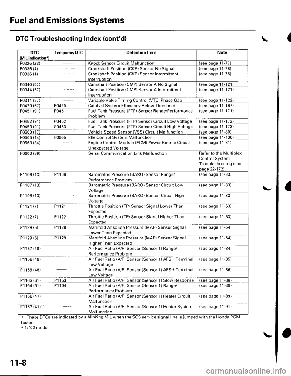
Fuel and Emissions Systems
Knock Sensor Circuit N4alfunction
Crankshaft Position (CKP) Sensor Intermittent(see page 11-78)
(see oaqe 11-121
PO4i{
TU45I
P0452
Camshaft Position (CMP) Sensor A Intermiftentisee page 11-121)
Yetrgb-le Velye TiTing _controlll/T!) Phqse Gsee oaoe 11-122
CqJalyst System Elficie-ncy Below Thresholdsee oaqe 1 1- 167
Fuel Tank Pressure (FTP) Sensor Range/Performance (seepagell 171)
Sensor Circuit Low V11-172
Fuel Tank Pressure (FTP) Sensor Circuit High V
Vehicle SDeed SensorCircuit Malf unction
Camshaft Position (CMP) Sensor A No
P0451 (91)
see Daqe 11-130)
(see page 1 1-81)
Refer to the l\4ultiplex
Control System
Troubleshooting {see
(see page 1 1-83)
(see paSe 1 1'83)
Barometric Pressure (BARO) Sensor Circuit High{see page 11-83)
P't 121
Pl122
P11f,.8
Throttle Position {TPi Sensor Signal Lower Than(see page 11-63)
-tsee page I r-oJ,
G;tp"s" 1 154)
(*" paSe 1 154)
P1122 ll J
ij1128 (5)
Throttle Position (TP) Sensor Signal Higher Than
Mani{old Absolute Pressure (l\,4AP} Sensor Signal
Loqer Tha n Expected
Manifold Absolute Preisure (MAP) SeiiioiSgnul
Hiqher Than Ex(see page 11-84)
Engine Control Module (ECN4) Power Source Circuil
Serial Communication Link Malfunction
P1106 (13)
P110? (13
P1 108 (ts'
Barometric Pressure (BARO) Sensor Range/
Performance Problem
Barometric Pressure (BARO) Sensor Circuit Low
P1121 11)
P1 129 (5)
P1157 (48)
Pr 158 (48)
Air Fuel Ratio (AVF) Sensor (Sensor 1) Range/
Rerformance Problem
AirFuel Ratio{A"F) Sensor {Sensor 1)AFS Terminal(see page 1 1-85)
Air Fuel Ratio 1AVF) Sensor isensor 'l) AFS + Terminal(see page 1 1-86)
Air Fuel Ratio {A,/F) Sensor {Sensor I ) Slow Response
Air Fuel Ratio (A/F) Sensor (Sensor 1) Range/(see page 1 1-88)
Air Fuel Ratio (4,/F) Sensor (Sensor 1) Heater Circuit
Malfunction
(see page 11-89)
Air Fuel Ratio (A,/F) Sensor (Sensor 1) Heater System
Malfunction
(see page 11-91)
P1 159 (48)
P1163 (61
P1164 (61)
P1 166 (41)
P1 167 (41) '
DTC Troubleshooting Index (cont'd)
" :These DTCS are indicated by a blinking MIL when the SCS servlce signal line is jumped with the Honda PGM
Tester.* 1r '02 model
\
l\."
11-8
\.
(
a
Page 295 of 1139
PGM-FI System
DTC Troubleshooting (cont'dl
DTC Pl163: Ay'F Sensor (Sensor 1 ) SlowResponse
NOTE: lf DTC P1162 is stored at the same time as DTC
P1163. troubleshoot DTC P1162 first, then recheckfor
DTC P1163.
1. Reset the ECM (see page 1 1-4).
2. Start the engine. Hold the engine at 3,000 rpm with
no load (in neutral) until the radiator fan comes on.
3. Test-drive under the following conditions:
. 55 mph (89 km/h) steady speed' Transmission in sth gear' Until the Ay'F sensor readiness code or
Temporary DTC Pl163 comes on
4. Check for a Temporary DTC with the scan tool.
ls Temporary DTC P 1163 indicated?
YES Replace the Ay'F sensor (Sensor 1).I
NO Intermittent failu re, system is OK at this time.
Check for poor connections or loose terminals at
the A'lF sensor (Sensor 1 ) and at the ECM. t
11-88
DTC Pl164: A,/F Sensor (Sensor 1) Circuit
Range/Performance Problem
1. Resetthe ECI\4 (see page 1t-4).
2. Start the engine. Holdtheengineat3,000 rpmwith
no load (in neutral) until the radiator fan comes on,
3. Test-drive in 3rd gear. Starting at 1,600 rpm,
accelerate using wide open throttle for at least
5 seconds. Then decelerate for at least 5 seconds
with the throttle completely closed until the A,/F
sensor readiness code is set to complete or
Temporary DTC P1 164 comes on.
4. Check for a Temporary DTC with the scan tool.
ls Temporary DTC P1164 indicated?
YES- Replace the A,,/F sensor (Sensor 1). I
NO Intermittent failure, system is OK at this time.
Check for poor connections or loose terminals at
the Ay'F sensor relay, at the Ay'F sensor (Sensor 1),
and at the EcM.l
Page 829 of 1139
Heating and Air Conditioning
A/C System Tests (cont'd)
1.
Performance Test
Air conditioning refrigerant or lubricant vapor
can irritate your eyes, nose, or throar.
Be carefulwhen connecting service equipment.
Do not breathe refrigerant or vapor.
The performance test will help determine if the air
conditioner system is operating within specifications.
Use only service equipment that is U.L.-listed and is
cenified to meet the requirements of SAE J2210 toremove HFC-134a (R-134alfrom the air conditioning
system.
lf accidental system discharge occurs, ventilate the
work area before resuming service
R-134a service equipment or vehicle air conditioning
systems should not be pressure tested or leak testedwith compressed air.
Additional health and safety information may be
obtained from the refrigerant and lubricant
manufacturers.
Connect a R-134a refrigerant recover/recycling/
charging station to the high-pressure service port
and the low-pressure service port, following the
equipment manufacturer's instructions.
Determine the relative humidity and air
Iemperaru re.
' Compressed air mixed with R-134a forms a
combustible vapor.. The vapor can burn or explode causing serious
Injury.. Never use compressed air to pressure test
R-134a service equipment or vehicle air
conditioning systems.
21-58
4.
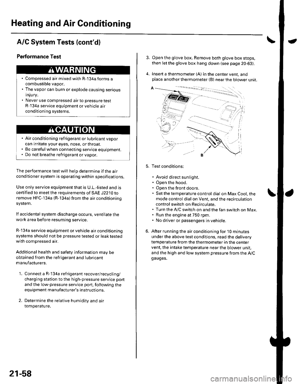
Open the glove box. Remove both glove box stops,
then let the glove box hang down (see page 20-63).
Insert a thermometer (A) in the center vent, andplace another thermometer {B) near the blower unit.
Test conditions:
. Avoid direct sunlight.. Open the hood.. Open the front doors.. Sel the temperature control dial on Max Cool, the
mode control dial on Vent, and the recirculation
control switch on Recirculate.. Turn the A,/C switch on and the fan switch on Max.. Run the engine at 750 rpm.. No driver or passengers in vehicle.
After running the air conditioning for I0 minutes
under the above test conditjons, read the delivery
temperature from the thermometer in the center
vent, the intake temperature near the blower unit,
and the high and low system pressure from the Ay'Cga uges.