steering wheel adjustment HONDA CIVIC 2002 7.G Workshop Manual
[x] Cancel search | Manufacturer: HONDA, Model Year: 2002, Model line: CIVIC, Model: HONDA CIVIC 2002 7.GPages: 1139, PDF Size: 28.19 MB
Page 495 of 1139
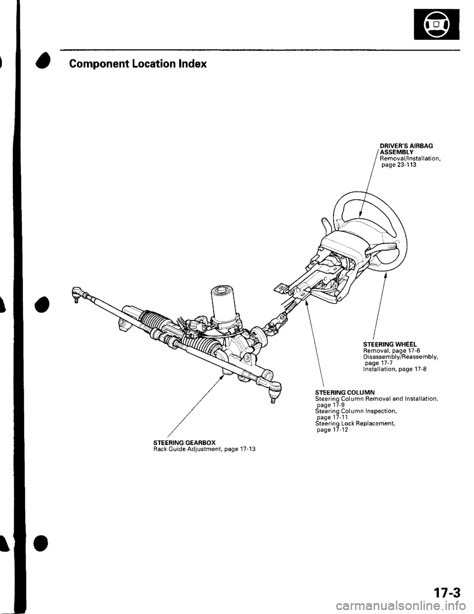
Component Location Index
DRIVER'S AIRBAGASSEMBLYRemoval/lnstallation,page 23-113
STEERING WHEELRemoval, page 17-6Disassembly/Reassembly,page 17 -7Installation, page 17-8
STEERING COLUMNSteering Column Removal and Installation,page 17'9Steering Column Inspection,page 17-1'lSteering Lock Replacement,page 11-12
STEERING GEARBOXRack Guide Adjustment, page '17-13
17-3
Page 496 of 1139
Steering
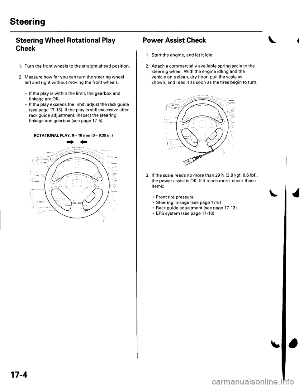
Steering Wheel Rotational Play
Check
1. Turn the front wheels to the straight ahead position.
2. Measure how far you can turn the steering wheel
left and right without moving the front wheels.
. lf the play is within the limit, the gearbox and
linkage are OK.. lf the playexceedsthe limit, adjustthe rack guide
{see page '17-13). lf the play is still excessive after
rack guide adjustment, inspect the steering
linkage and gearbox {see page 17-5).
BOTATIONAL PLAY: 0 10 mm (0-0.39 in.l
+:
17-4
Power Assist Check
Start the engine, and let it idle.
Attach a commercially available spring scale to the
steering wheel. With the engine idling and the
vehicle on a clean, dry floor, pull the scale as
shown, and read it as soon as the tires begin to turn.
\
1.
3. lf the scale reads no morethan 29 N (3.0 kgf,6.6 lbf),
the power assist is OK. lf it reads more, check these
items:
. Front tire pressure. Steering linkage (see page 17-5). Rack gulde adjustment (see page 17-13). EPS system (see page 17-18)
Page 505 of 1139
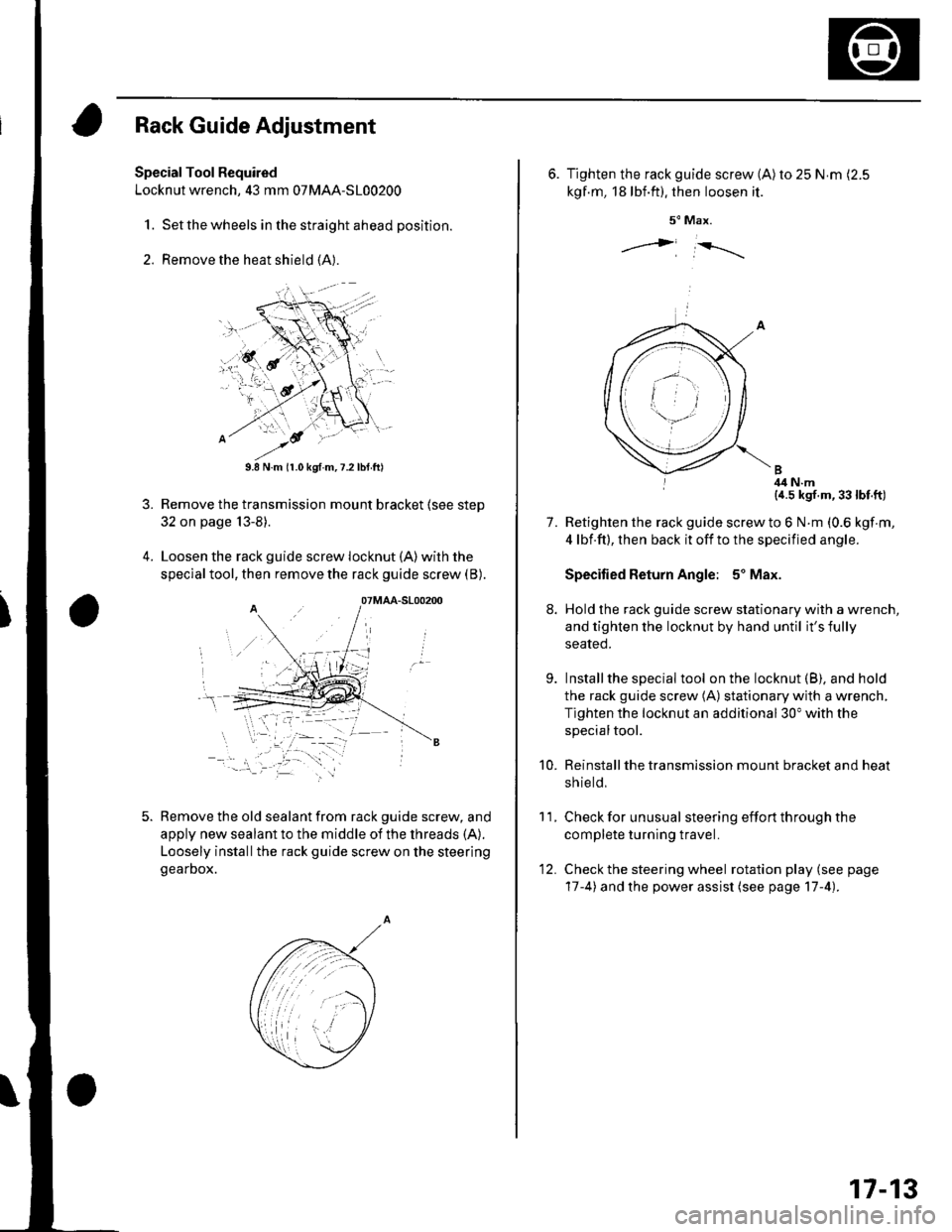
Rack Guide Adjustment
Special Tool Required
Locknut wrench, 43 mm 07MAA-S100200
1. Set the wheels in the straight ahead position.
2. Remove the heat shield (A).
3.
9.8 N.m (r.0 kgf.m,7.2lbtft)
Remove the transmission mount bracket (see step
32 on page 13-8).
Loosen the rack guide screw locknut (A)with the
special tool, then remove the rack guide screw (B).
Remove the old sealant from rack guide screw, and
apply new sealant to the middle of the threads (A).
Loosely installthe rack guide screw on the steering
gearDox.
'-.i. '' '
07MAA-S100200
6. Tighten the rack guide screw (A)ro 25 N.m (2.5
kgf.m, 18lbf.ft). then loosen it.
5" Max.
j i-rrrr-,
I 4il N.m{a.5 kgf.m,33lbt.ft)
Retighten the rack guide screw to 6 N.m (0.6 kgf m,
4 lbf.ft), then back it off to the specified angle.
Specified Return Angle: 5' Max.
Hold the rack guide screw stationary with a wrench,
and tighten the locknut by hand until it's fully
seated.
Installthe special tool on the locknut (B), and hold
the rack guide screw (A) stationary with a wrench,
Tighten the locknut an additional 30" with the
specialtool.
Reinstall the transmission mount bracket and heat
sh ie ld,
Check for unusual steering effort through the
complete turning travel.
Check the steering wheel rotation play (see page
17-4) and the power assist (see page 17-4).
11.
7.
9.
10.
12.
17-13
Page 565 of 1139
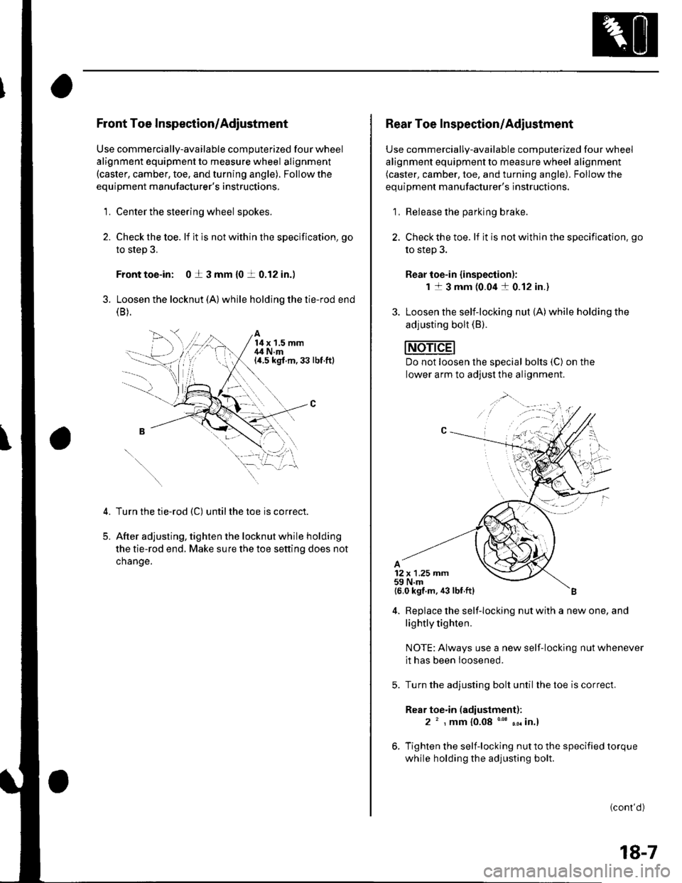
Front Toe Inspection/Adjustment
Use commercially-available computerized four wheel
alignment equipment to measure wheel alignment(caster, camber, toe, and turning angle). Follow the
equipment manufacturer's instructions,
1. Center the steering wheel spokes.
2. Checkthetoe. lf it is not with in the specif ication, go
to step 3.
Front toe-in: 0 t 3 mm {0 t 0.12 in.)
3. Loosen the locknut (A) while holding the tie-rod end(B ).
A14x 1.5 mm,14 N.m(a.5 kgt m,33 lbt.ftl
5.
Turn the tie-rod (C) untilthe toe is correct.
After adjusting, tighten the locknut while holding
the tie-rod end. Make sure the toe setting does not
change.
1,;
Rear Toe Inspection/Adiustment
Use commercially-available computerized four wheel
alignment equipment to measure wheel alignment(caster, camber, toe, and turning angle). Follow the
equipment manufacturer's instructions.
1, Release the parking brake.
2. Checkthe toe. lf it is not within the specification. go
to step 3.
Rear toe-in {inspection):
1 1 3 mm (0.04 a 0.12 in.)
3. Loosen the self-locking nut (A)while holding the
adjusting bolt (B).
Do not loosen lhe special bolts (C) on the
lower arm to adjust the alignment.
4. Replace the self-locking nut with a new one, and
lightly tighten.
NOTE: Always use a new self-locking nut whenever
it has been loosened.
Turn the adjusting bolt until the toe is correct.
Rear toe.in (adiustment):
2 ' , mm {0.08 "' ,. in.}
Tighten the self-locking nut to the specified torque
while holding the adjusting bolt.
(cont'd )
18-7
Page 1021 of 1139
sRs
Precautions and Procedures
General Precautions
Please read the following precautions carefully beforeperforming airbag system service. Observe theinstructions described in this manual. or the airbags
could accidentally deploy and cause damage or injuries.
. Except when performing electrical inspections.
always turn the ignition switch OFF, disconnect the
negative cable from the battery, and wait at least 3minutes before beginning work.
NOTE: The memory is not erased even if the ignition
switch is turned OFF or the battery cables are
disconnected from the battery.. Use replacement pans which are manufactured to the
same standards and quality as the original parts. Do
not install used SRS parts from another vehicle. Useonly new pans when making SRS repairs.. Carefully inspect any SRS part before you install it.
Do not install any part that shows signs of being
dropped or improperly handled, such as dents, cracks,
or deformation.
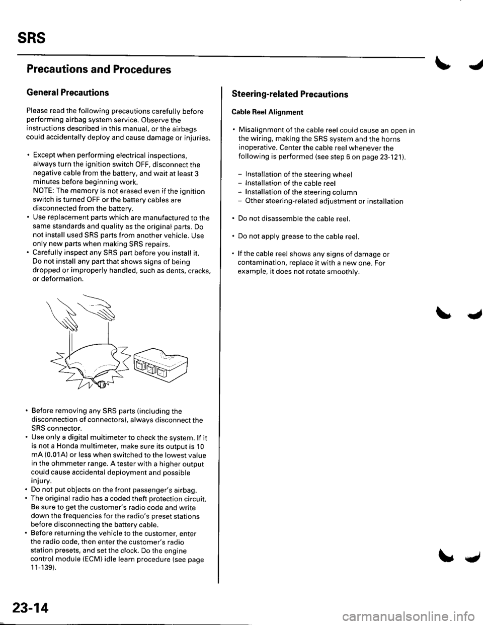
. Before removing any SRS parts (including the
disconnection of connectors), always disconnect the
SRS connector.. Use only a digital multimeter to check the system. lf itis not a Honda multimeter, make sure its outout is 10mA (0.01A) or less when switched to the lowest value
in the ohmmeter range. A tester with a higher output
could cause accidental deployment and possible
injury.. Do not put objects on the front passenger's airbag.. The original radio has a coded theft protection circuit.
Be sure to get the customer's radio code and write
down the frequencies for the radio's preset stations
before disconnecting the battery cable.. Before returning the vehicle to the customer, enter
the radio code. then enter the customer's radio
station presets, and set the clock. Do the engine
control module (ECM) idle learn procedure (see page
11-139).
23-14
c
Steering-related Plecautions
Cable Reel Alignment
. Misalignment of the cable reel could cause an open in
the wiring, making the SRS system and the horns
inoperative. Center the cable reel whenever the
following is performed (see step 6 on page 23-121).
- Installation of the steering wheel- Installation of the cable reel- Installation ofthe steering column- Other steering-related adjustment or installation
. Do not disassemble the cable reel.
. Do not apply grease to the cable reel.
. lf the cable reel shows any signs of damage or
contamination. replace it with a new one. For
example, it does not rotate smoothly.