Front HONDA CIVIC 2003 7.G Workshop Manual
[x] Cancel search | Manufacturer: HONDA, Model Year: 2003, Model line: CIVIC, Model: HONDA CIVIC 2003 7.GPages: 1139, PDF Size: 28.19 MB
Page 755 of 1139
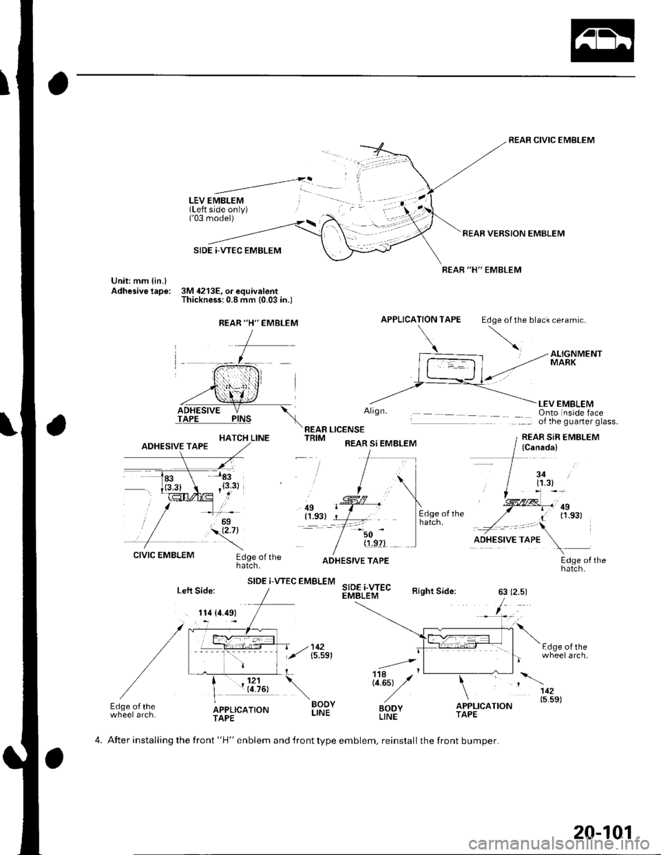
LEV EMBLEM(Left side only)('03 model)
SIDE |-VTEC EMBLEM
Unit: mm {in.lAdhesive tape: 3M 4213E, o. equivalentThickness:0.8 mm (0.03 in.)
REAR CIVIC EMBLEM
REAR VERSION EMBLEM
REAR "H" EMBLEM
APPLICATION TAPE Edoe ol the black ceramic.
HATCH LINE
Align.
REAR LICENSETRIM REAR si EMBLEM
LEV EMBLEMOnto inside faceof the guarter glass.
REAR SiR EMBLEM
, ilg(1.93)=-t
50
CIVIC EMBLEMEdge ofthehatch.
SIDE i-VTEC EMBLEM
{'!,9?)
SIDE i.WECEMBLEM
ADHESIVE TAPEEdge of thehatch.
Right Side:63 (2.5)
F.l^6 ^l rh-
.=4,
Li.Est y'
BODYLINE
wheelarch.
112
BODYLINEo"f,r,ao.o" (5'5s)Edge of thewheel arch.APPLICATIONTAPETAPE
REAR "H'' EMBLEM
(Canada)
3411.3)
.,!!ll,'ntI (1.s31
Left Side:
. 114 (4.49)
4. After installing the front "H" enblem and front type emblem, reinstall the front bumper.
20-101
Page 756 of 1139
Fenderwell
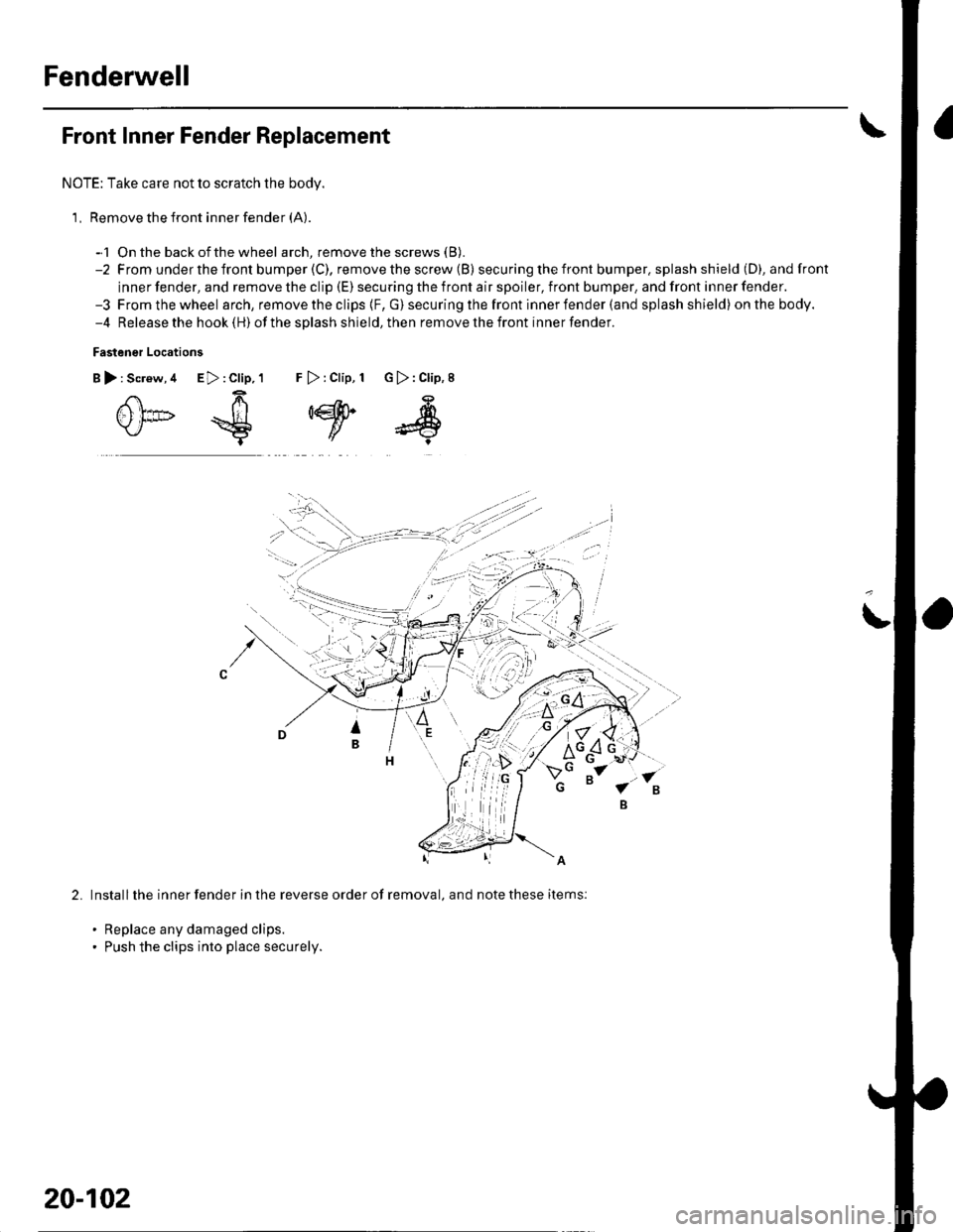
Front Inner Fender Replacement
NOTE: Take care not to scratch the body.
1, Remove the front inner fender (A).
-1 On the back ofthe wheel arch, remove the screws (B).
-2 From underthefront bumper(C), removethescrew (B) secu ring the front bumper. splash shield (D), andfront
inner fender, and remove the clip (E) securing the front air spoiler, front bumper, and front inner fender.-3 Fromthewheel arch, remove the clips {F, G) securing the front inner fender (and splash shield) onthebody.-4 Release the hook (H) ofthe splash shield,then removethefront innerfender.
Fastener Locations
B):Screw,4 E>:Clip,1 F >:Clip, 1 G):Clip,8
0*€
,w
s
2.Install the inner fender in the reverse order of removal, and note these items:
. Replace any damaged clips.. Push the clips into place securely.
20-102
Page 757 of 1139
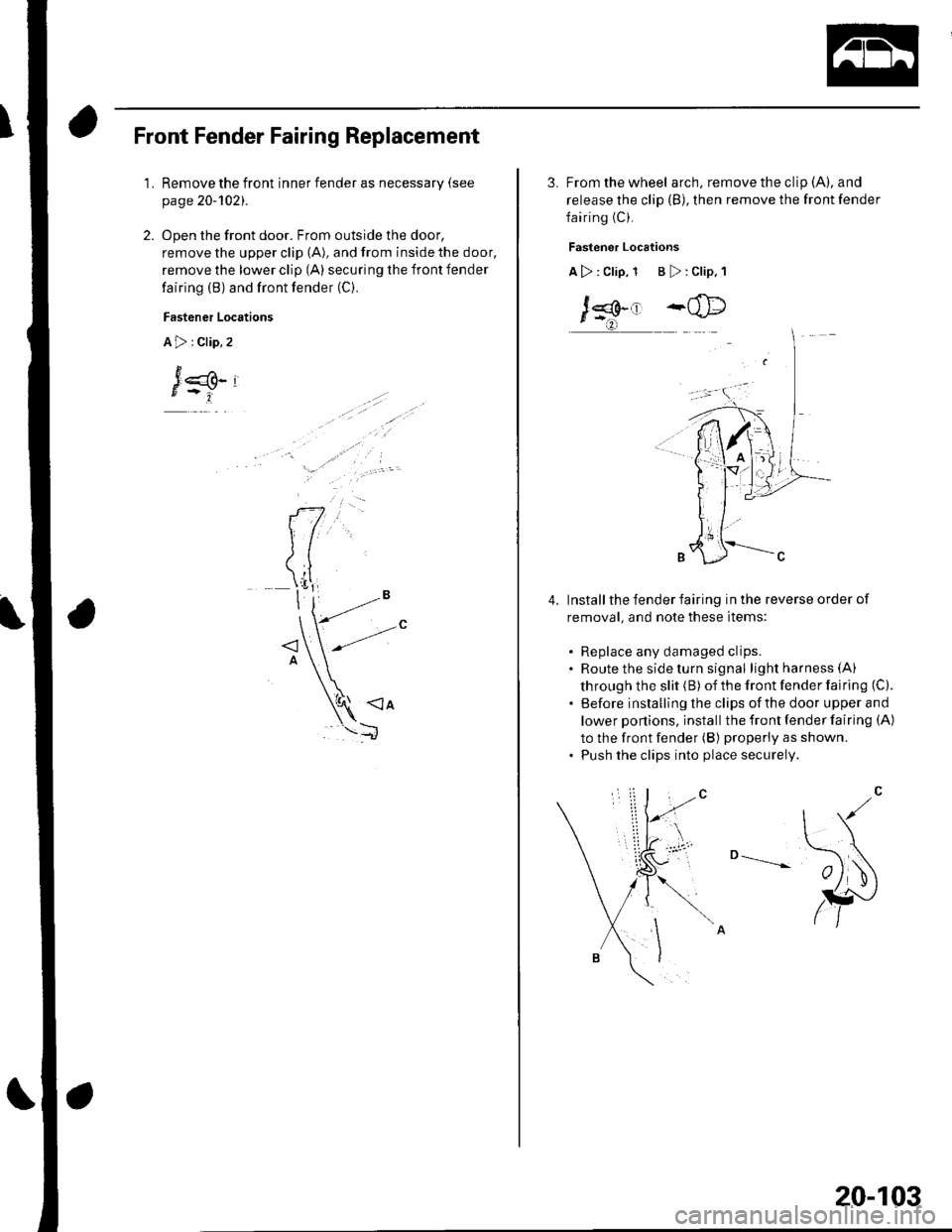
Front Fender Fairing Replacement
1.Remove the front inner fender as necessary (see
page 20-1O21.
Open the front door. From outside the door,
remove the upper clip (A), and from inside the door,
remove the lower clip (A) securing the front fender
fairing (B) and front fender (C).
Fastener Locations
A>:Clip,2
J
3. From the wheel arch, remove the clip (A), and
release the clip (B), then remove the front fender
fairing (C).
Fastener Locations
A>: Clip, 1 B >: Clip, 1
J*.' -@
Install the fender fairing in the reverse order of
removal, and note these items:
. Replace any damaged clips.. Route the side turn signal lightharness(A)
through the slit (B) of the front fender fairing (C).
. Before installing the clips ofthe door upper and
lower ponions, install the front fender fairing (A)
to the front fender (B) properly as shown.. Push the clips into place securely.
o --____--
4.
20-103
Page 760 of 1139
Openers
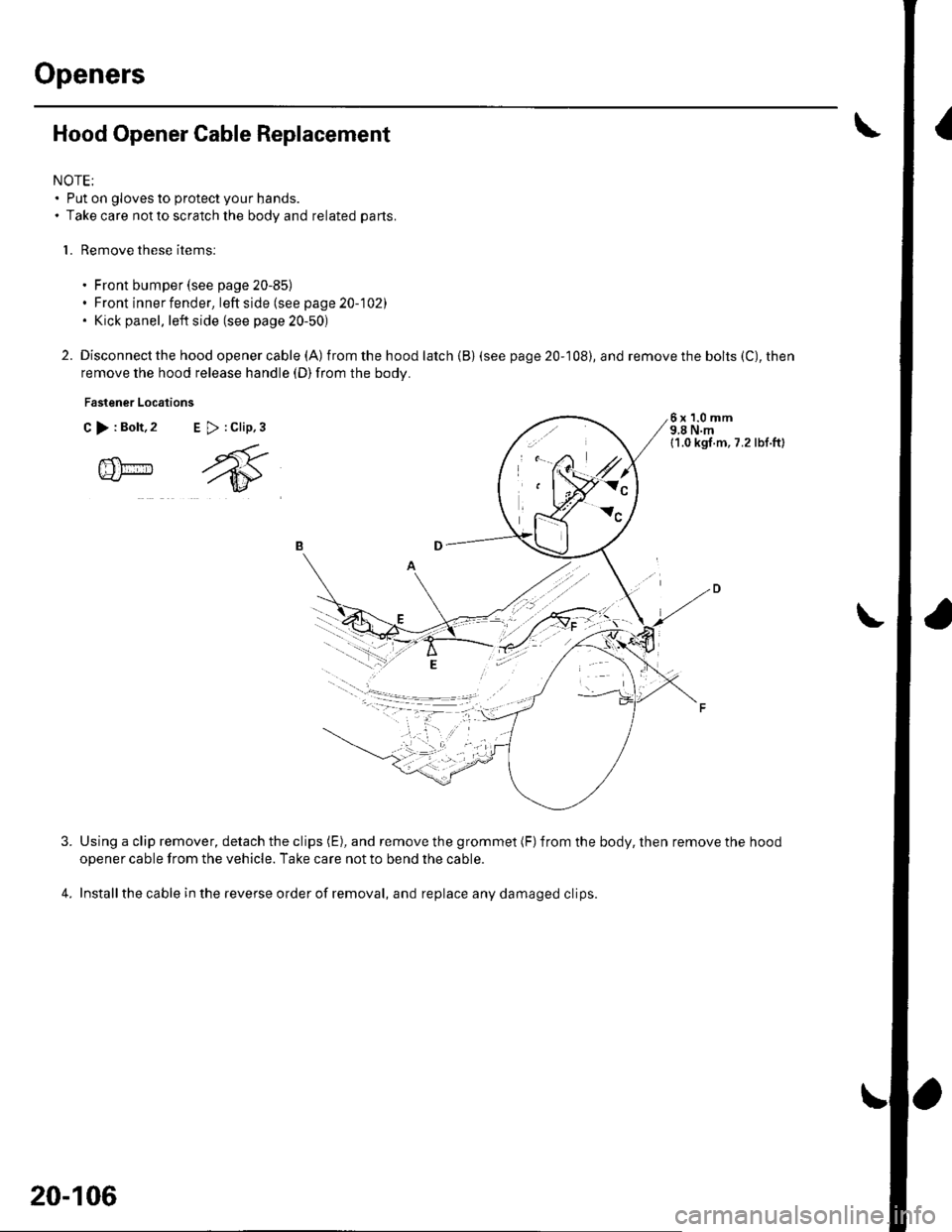
Hood Opener Cable Replacement
NOTE:. Put on gloves to protect your hands.. Take care not to scratch the body and related parts.
l. Remove these items:
. Front bumper (see page 20-85). Front inner fender, leftside(seepage20-102). Kick panel, left side (see page 20-50)
2. Disconnect the hood openercable (A) from the hood latch {B) (see
remove the hood release handle (D)from the body.
Fastener Locations
C >:Bolt,2 E >:Clip,3
page 20-108), and remove the bolts (C), then
6x1.0mm9,8 N.m11.0 kgl.m, 7.2 lbl.ft)
@m
4.
Using a clip remover, detach the clips (E), and remove the grommet (F)from the body, then remove the hood
opener cable from the vehicle. Take care not to bend the cable.
Installthe cable in the reverse order of removal, and replace any damaged clips.
l,.t'.
W:"
20-106
Page 763 of 1139
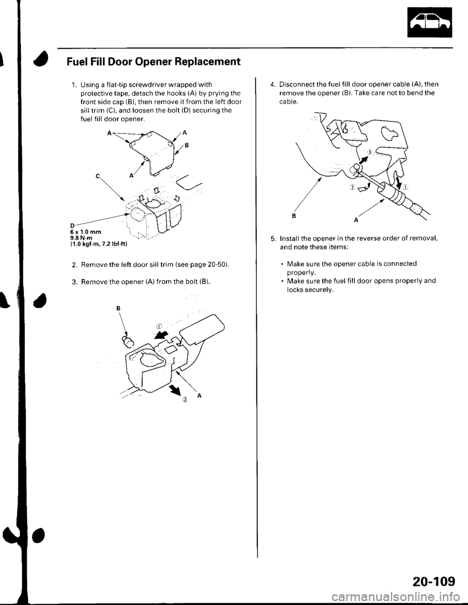
Fuel Fill Door Opener Replacement
1.Using a flat-tip screwdriver wrapped with
protective tape, detach the hooks (A) by prying the
front side cap (B), then remove it from the left door
silltrim (C), and loosen the bolt (D) securing the
fuel fill door opener.
6x1.0mm9.8 N.m11.0 kgf m,7.2 lbf.ft)
Remove the left door sill trim (see page 20-50i.
Remove the opener (Alfrom the bolt {B).
2.
3.
4. Disconnect the fuel fill door opener cable (A), then
remove the opener iB). Take care not to bend the
ca o te.
Installthe opener in the reverse order of removal,
and note these items:
5.
lMake sure the opener cable is connected
properly.
lvlake sure the fuel fill door opens properly and
locks securely.
20-109
Page 766 of 1139
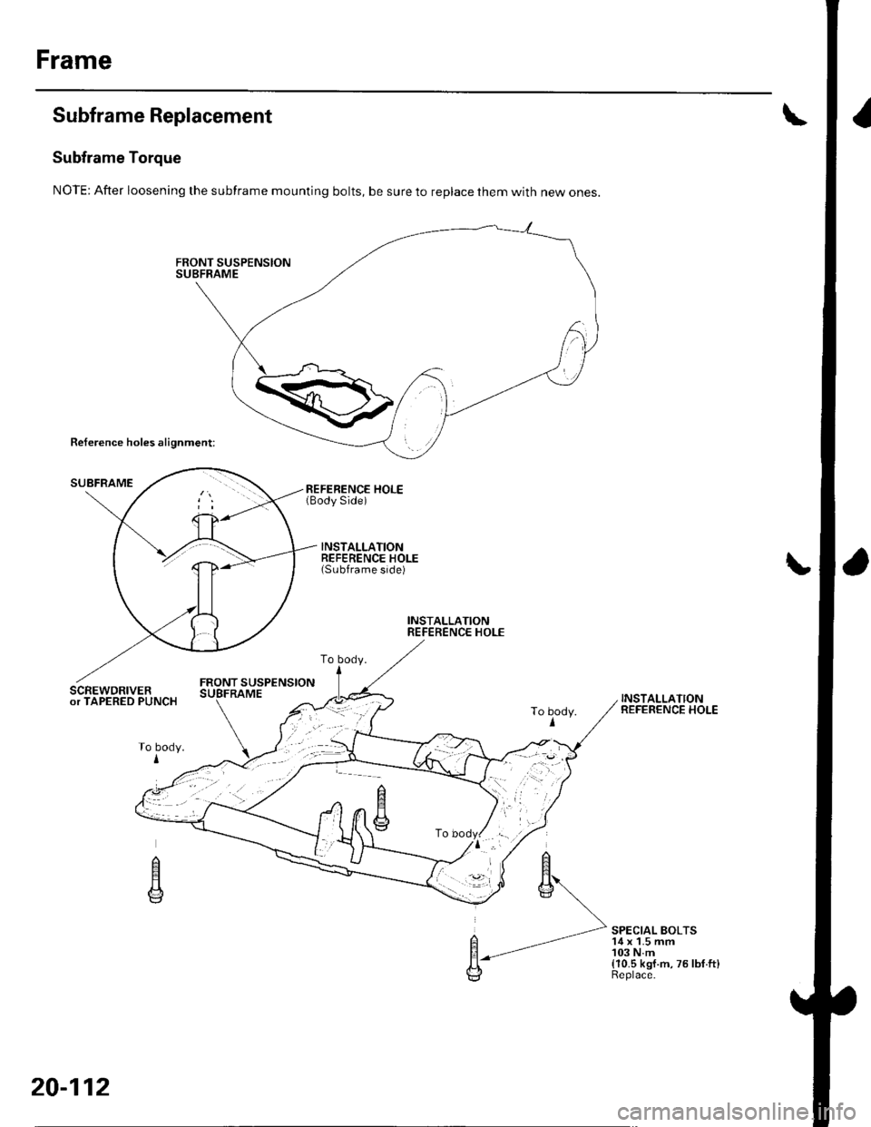
Frame
Subframe Replacement
Subframe Torque
NOTE: After loosening the subframe mounting bolts, be sure to replace them with new ones.
Reference holes alignment:
SUBFRAMEREFERENCE HOLE(Body Side)
INSTALLATIONREFERENCE HOLE(Subframe side)
INSTALLATIONREFERENCE HOLE
FRONT SUSPENSIONSCREWDRIVERor TAPERED PUNCHINSTALLATIONREFERENCE HOLE
SPECIAL BOLTS'14 x 1.5 mm103 N.m(10.5 kgf.m,75lbf.ft)Replace.
To body.
To body.I
n
E
20-112
Page 823 of 1139
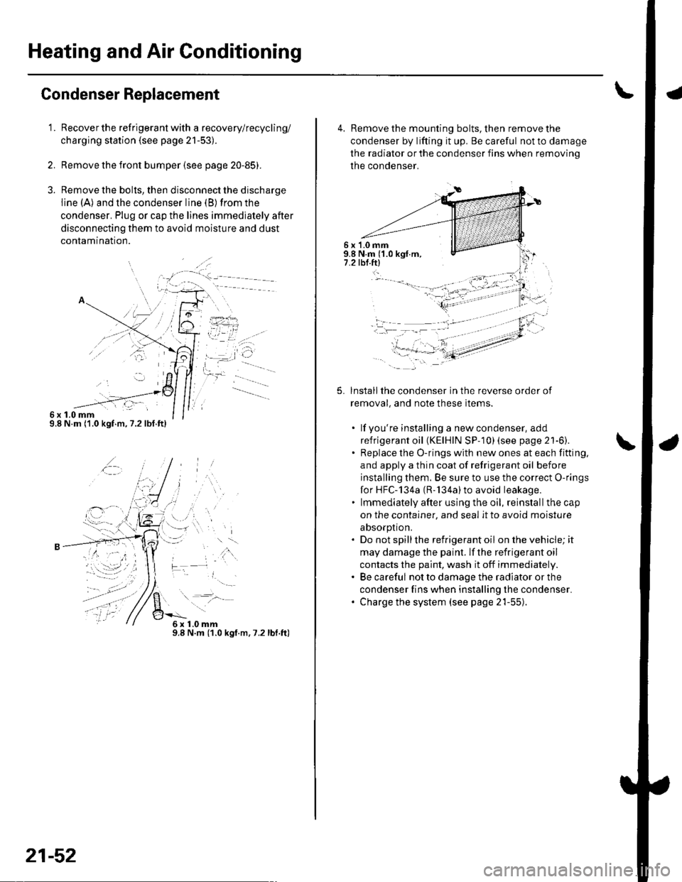
Heating and Air Conditioning
Gondenser Replacement
1.
6x1.0mm9.8 N.m ('1.0 kgf.m,7.2lbf.ft)
Recover the refrigerant with a recovery/recycling/
charging station (see page 21-53).
Remove the front bumper {see page 20-85).
Remove the bolts, then disconnect the discharge
line (A) and the condenser line (B) from the
condenser. Plug or cap the lines immediately after
disconnecting them to avoid moisture and dust
conlamtnaflon.
,t\
6x1.0mm9.8 N.m (1.0 kgt.m.7.2lbf.ft)
21-52
4, Remove the mounting bolts, then remove the
condenser by lifting it up. Be careful not to damage
the radiator or the condenser fins when removino
the condenser.
6 x '1.0 mm9.8 N.m ('1.0 kgf.m,7.2 tbl.ftl
5.lnstallthe condenser in the reverse order of
removal, and note these items.
. lf you're installing a newcondenser, add
refrigerant oil (KElHlN SP- 10) lsee page 21'6).. Replace the O-rings with new ones at each fitting,
and apply a thin coat of refrigerant oil before
installing them. Be sure to use the correct O-rings
for HFC-134a (R-'134a)to avoid leakage.. lmmediately after using the oil, reinstallthe cap
on the container, and seal it to avoid moisture
absorption.. Do not spillthe refrigerant oil onthevehicle;it
may damage the paint. lf the refrigerant oil
contacts the paint, wash it off immediately.. Be careful not to damage the radiator or the
condenser fins when installing the condenser.. Charge the system (see page 21-55).
t -"'.
f,
t-
-li .:)-:.-- ---- - -'
Page 829 of 1139
Heating and Air Conditioning
A/C System Tests (cont'd)
1.
Performance Test
Air conditioning refrigerant or lubricant vapor
can irritate your eyes, nose, or throar.
Be carefulwhen connecting service equipment.
Do not breathe refrigerant or vapor.
The performance test will help determine if the air
conditioner system is operating within specifications.
Use only service equipment that is U.L.-listed and is
cenified to meet the requirements of SAE J2210 toremove HFC-134a (R-134alfrom the air conditioning
system.
lf accidental system discharge occurs, ventilate the
work area before resuming service
R-134a service equipment or vehicle air conditioning
systems should not be pressure tested or leak testedwith compressed air.
Additional health and safety information may be
obtained from the refrigerant and lubricant
manufacturers.
Connect a R-134a refrigerant recover/recycling/
charging station to the high-pressure service port
and the low-pressure service port, following the
equipment manufacturer's instructions.
Determine the relative humidity and air
Iemperaru re.
' Compressed air mixed with R-134a forms a
combustible vapor.. The vapor can burn or explode causing serious
Injury.. Never use compressed air to pressure test
R-134a service equipment or vehicle air
conditioning systems.
21-58
4.
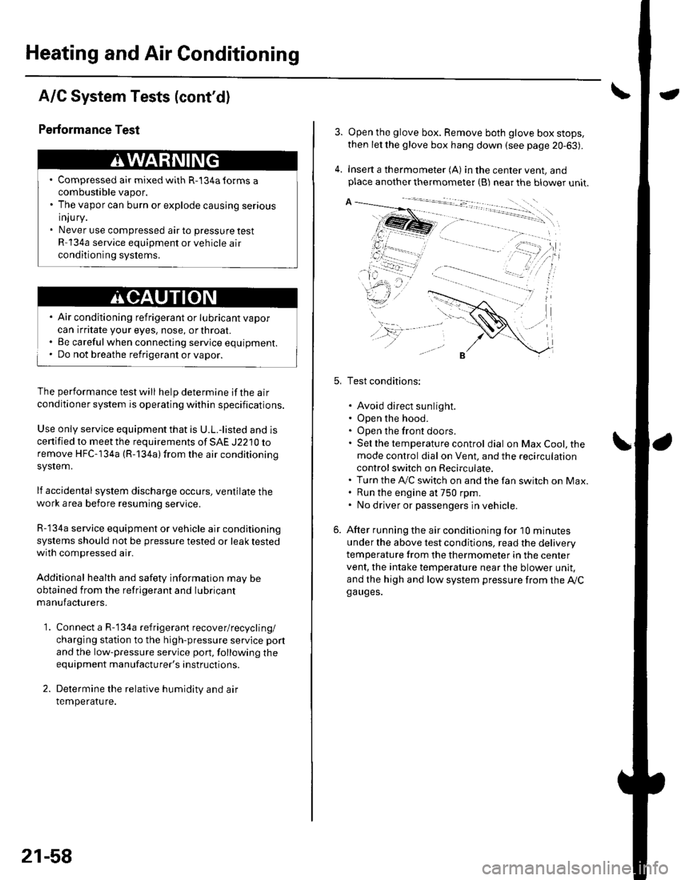
Open the glove box. Remove both glove box stops,
then let the glove box hang down (see page 20-63).
Insert a thermometer (A) in the center vent, andplace another thermometer {B) near the blower unit.
Test conditions:
. Avoid direct sunlight.. Open the hood.. Open the front doors.. Sel the temperature control dial on Max Cool, the
mode control dial on Vent, and the recirculation
control switch on Recirculate.. Turn the A,/C switch on and the fan switch on Max.. Run the engine at 750 rpm.. No driver or passengers in vehicle.
After running the air conditioning for I0 minutes
under the above test conditjons, read the delivery
temperature from the thermometer in the center
vent, the intake temperature near the blower unit,
and the high and low system pressure from the Ay'Cga uges.
Page 844 of 1139
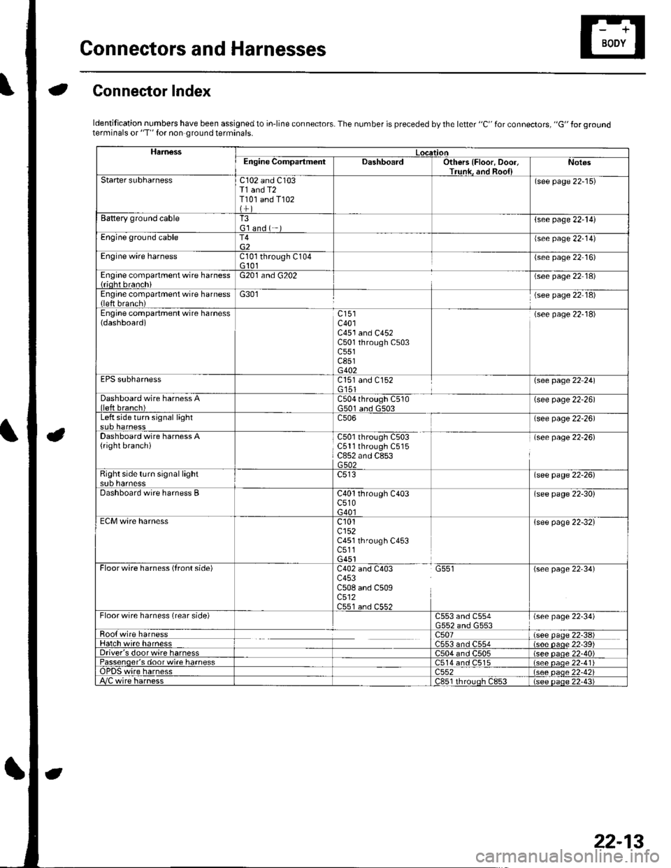
Gonnectors and Harnesses
aGonnector Index
ldentification numbers have been assigned to in-line connectors. The number is preceded by the letter "C" for connectors, "G" for groundterminals or "T" for non ground terminals.
HamessLocationEngine CompartmentDashboardOthers {Floor, Door,Trunk. and Roo{lNot€s
Starter subharnessC102 and C103T1 and T2T101 and T102
(see page 22-15)
Battery ground cableT3G'l and ( -{see page 22-l!)
Engine ground cableT4{see page 22-14)
Engine wire harnessCl0l through C104G 101(see page 22 16)
Engine compartment wire harness{rioht branchiG201 and G202(see page 22 18)
Engine compartment wire harness(left brench)G301(see page 22 18)
Engine compartment wire harness(dashboard)c401C451 and C452C501 through C503c551c851G402
(see page 22-18)
EPS subharnessC151 and C152G'151\see page 22 241
Dashboard wire harness Alleft branch)C504 through C510G501 and G503(see page 22-26)
Left side turn signal lightc506(see page 22-26)
Dashboard wire harness A(right branch)C50l through C503C5ll through C515C852 and C853G502
(see page 22-26)
Right side turn si9nal lightsub harnesslsee page 22-26)
Dashboard wire harness BC40l through C403c510G40l
(see page 22-30)
ECM wire harnessc101cl52C451 through C453c511G451
{see page 22-32}
Floorwire harness (front side)C402 and C403 G551c453C508 and C509c512C551 an.l C55?
(see page 22'34)
Floor wire harness (rear side)C553 and C554(see page 22-34)
Roo{ wire harnessc507(see paqe 22-38)Hatch wire harnessC553 and C554(s6e paqe 22'39)Driver's door wire harnessC504 and C505(see paqe 22-40)Passenqer's door wi.e harness514 and C515(see oaoe 22-41Te harness)552(see oaqe 22-42i/C wire harnessc851 rhrouoh c853(see paqe 22.43i
22-13
Page 846 of 1139
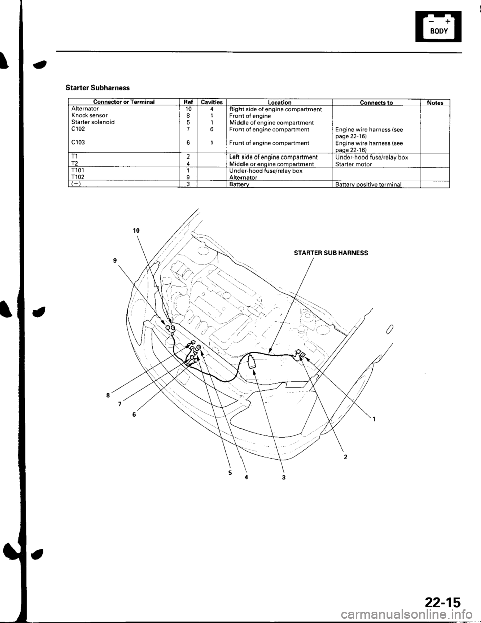
Connector or TerminalRetCavitiesLocationConnoc,ts toNotesAlternatorKnock sensorStarter solenoidc102
c103
10857
6
4116
1
Right side of eng;ne compartmentFront of engineMiddle of engine compartmentFront of engine compartment
Front of engane compartment
Engine wire harness (seepage 22 16)Engine wire harness (seeoaae 22-16)T1r224L€tt side of engine compartmentMiddle or enoine comDanmentUnder hood fuse/relay boxStaner motorT101r1021IUnder-hood fuse/relay boxAlternatorBattervBatterv positive terminal
Starter Subharness
STARTER SUB HARNESS
22-15