ecm HONDA CIVIC 2003 7.G Workshop Manual
[x] Cancel search | Manufacturer: HONDA, Model Year: 2003, Model line: CIVIC, Model: HONDA CIVIC 2003 7.GPages: 1139, PDF Size: 28.19 MB
Page 993 of 1139
lmmobilizer System
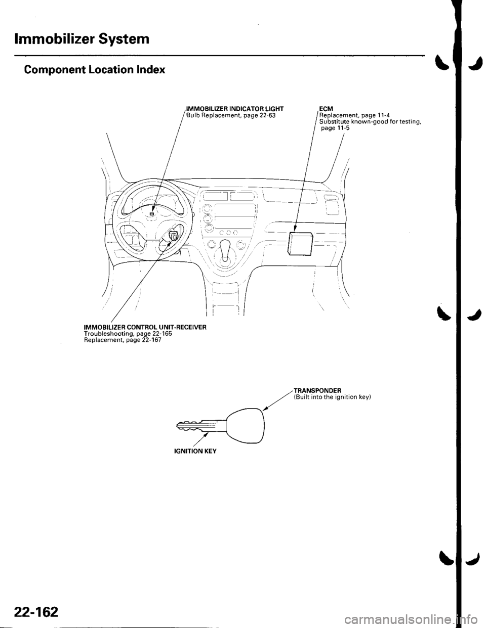
Component Location Index
INOICATOR LIGHTBulb Replacement, page 22 63ECMReplacement, page 11-4Substitute known-good for testing,page 11-5
IMMOBILIZER CONTROL UNIT.RECEIVERTroubleshooting, page 22-165Replacement, page 22-167
TRANSPONDER(8uilt into the ignition key)
22-162
Page 994 of 1139
System Description
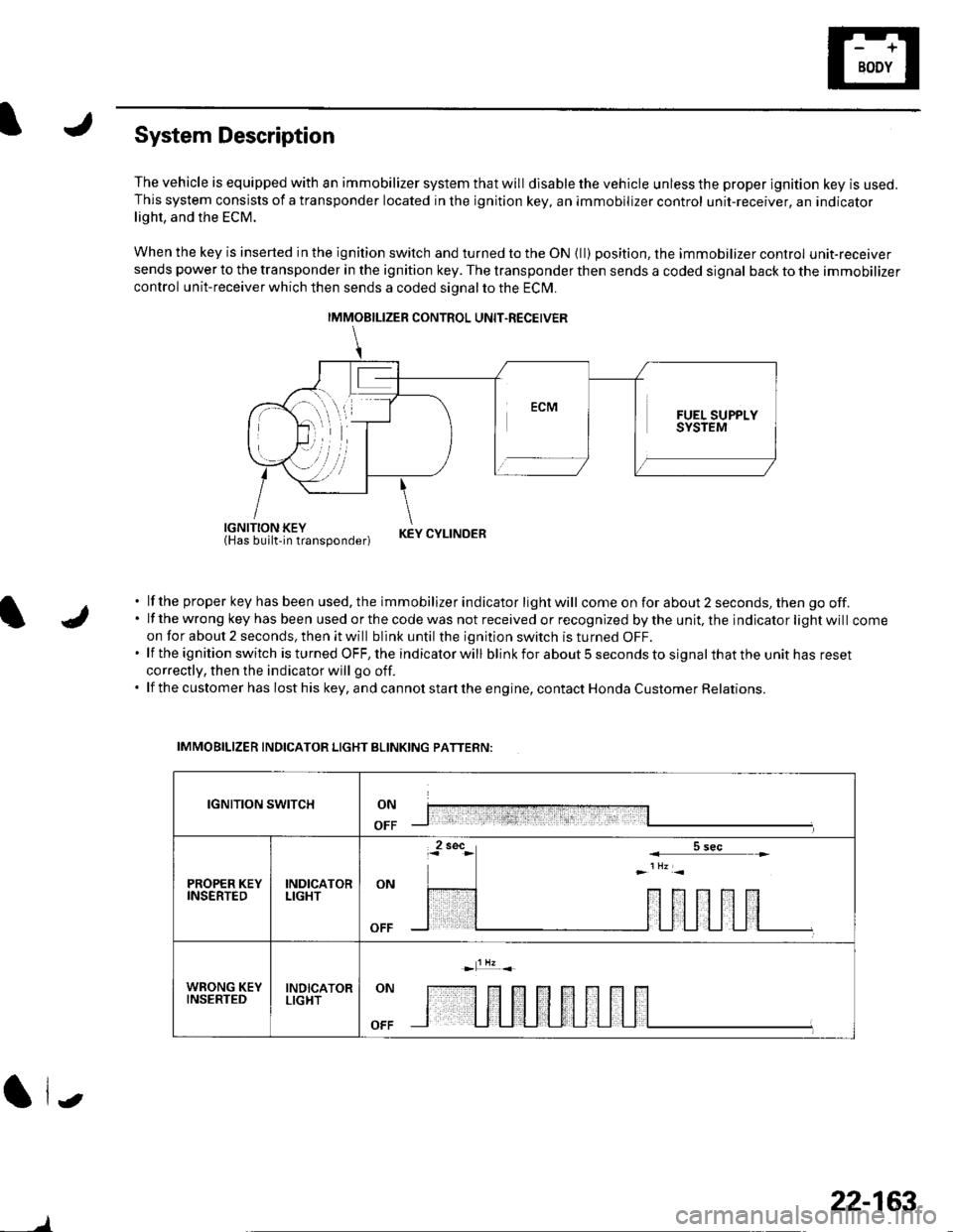
The vehicle is equipped with an immobilizer system that will disable the vehicle unless the proper ignition key is used.This system consists of a transponder located in the ignition key, an immobilizer control unit-receiver, an indicatorlight, and the ECM.
When the key is inserted in the ignition switch and turned to the ON {ll) position, the immobilizer control unit-receiversends power to the transponder in the ignition key. The transponder then sends a coded signal back to the immobilizer
control unit-receiver which then sends a coded signal to the ECI\4.
iEl'JUiliii'tlun"oona"|.r KEYCYLTNDER
lf the proper key has been used, the immobilizer indicator light will come on for about 2 seconds, then go off.lf the wrong key has been used or the code was not received or recognized by the unit, the indicator light will comeon for about 2 seconds, then it will blink until the ignition switch is turned OFF.lf the ignition switch is turned OFF, the indicator will blink for about 5 seconds to signal that the unit has reset
correctly, then the indicator will go off.
lf the customer has lost his key, and cannot start the engine, contact Honda Customer Relations.
IMMOBILIZER INDICATOR LIGHT BLINKING PATTERN:
IGNITION SWITCHON
OFF
PROPER KEYINSERTEDINDICATORLIGHTON
WRONG KEYINSERTEDINDICATORLIGHTON
OFF
(| i.,
IMMOBILIZER CONTROL UNIT.RECEIVER
)
22-163
Page 996 of 1139
)
I
Troubleshooting
Before troubleshooting the immobilizer system,
troubleshoot any EClvl Diagnostic Trouble Codes (DTCS)
(see page 11-3), and make sure the ECM has no
malfunction.
Note these items before trou bleshooting:
. Due to the action of the immobilizer system, the
engine takes slightly more time to start than on a
vehicle without an immobilizer system.. When the system is normal, and the proper key is
inserted, the indicator light comes on for 2 seconds,
then it will go off.. If the indicatorstartsto blink after 2 seconds, or if the
engine does not start. remove any other immobilizer
keys or large key fobs on the key ring, then repeat the
starting procedure.
lf the engine still does not start, continue with thisprocedure.
1. Turn the ignition switch ON {ll) with proper key.
2. Check to see if the immobilizer indicator light
comes on.
Does the indicator light blink?
YES Disconnect the 7P connector from the
immobilizer control unit-receiver, then go to step 9.
NO Check for these problems, then go to step 3.
. Blown No. 9 (10A)fuse in the under-hood
fuse/relay box.I. An open in the wire between the gauge assembly
and the immobilizer control unit-receiver.l. A faulty immobilizer indicator light,I. An open in the wire between the gauge assembly
and the under-hood fuse/relay box.l
Remove the driver's dashboard lower cover (see
page 20-59).
Remove the steering column lower cover (see page
11-9).
l
-_--t
22-165
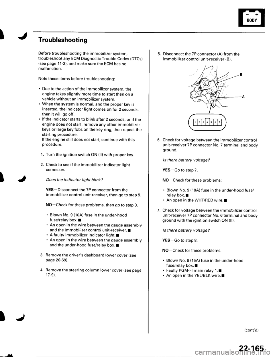
5. Disconnect the 7P connector (A)from the
immobilizer control unit-receiver (B),
Check for voltage between the immobilizer control
unit-receiver 7P connector No. 7 terminal and body
ground.
ls there battery voltage?
YES-Go to step 7.
NO Check for these problems;
. Blown No. 9 {10A)fuse in the under-hood fuse/
relay box.l. An open in the WHT/RED wire.l
Check for voltage between the immobilizer control
unit-receiver 7P connector No. 6 terminal and bodyground with the ignition switch ON {ll).
ls there battery voltage?
YES- Go to step 8.
NO Check for these problems:
. Blown No.6 (15A)fuse in the under-hood
fuse/relay box,I. Faulty PGM-Fl main relay 1,t. An open in the YEUBLK wire.l
1.
(cont'd)
Page 997 of 1139
lmmobilizer System
Troubleshooting (cont'dl
8. Check for voltage betvveen the immobilizer control
unit-receiver 7P connector No. 6 terminal and No. 1
rermlnat.
ls thete battery voltage?
YES Go to step 12.
NO Check for these problems,
. Open on the BRNI/EL wire.l. Faulty ECM.I
9. Remove the driver's dashboard lower cover (see
page 20-59).
10. Remove the steering column lower cover (see page
17-9).
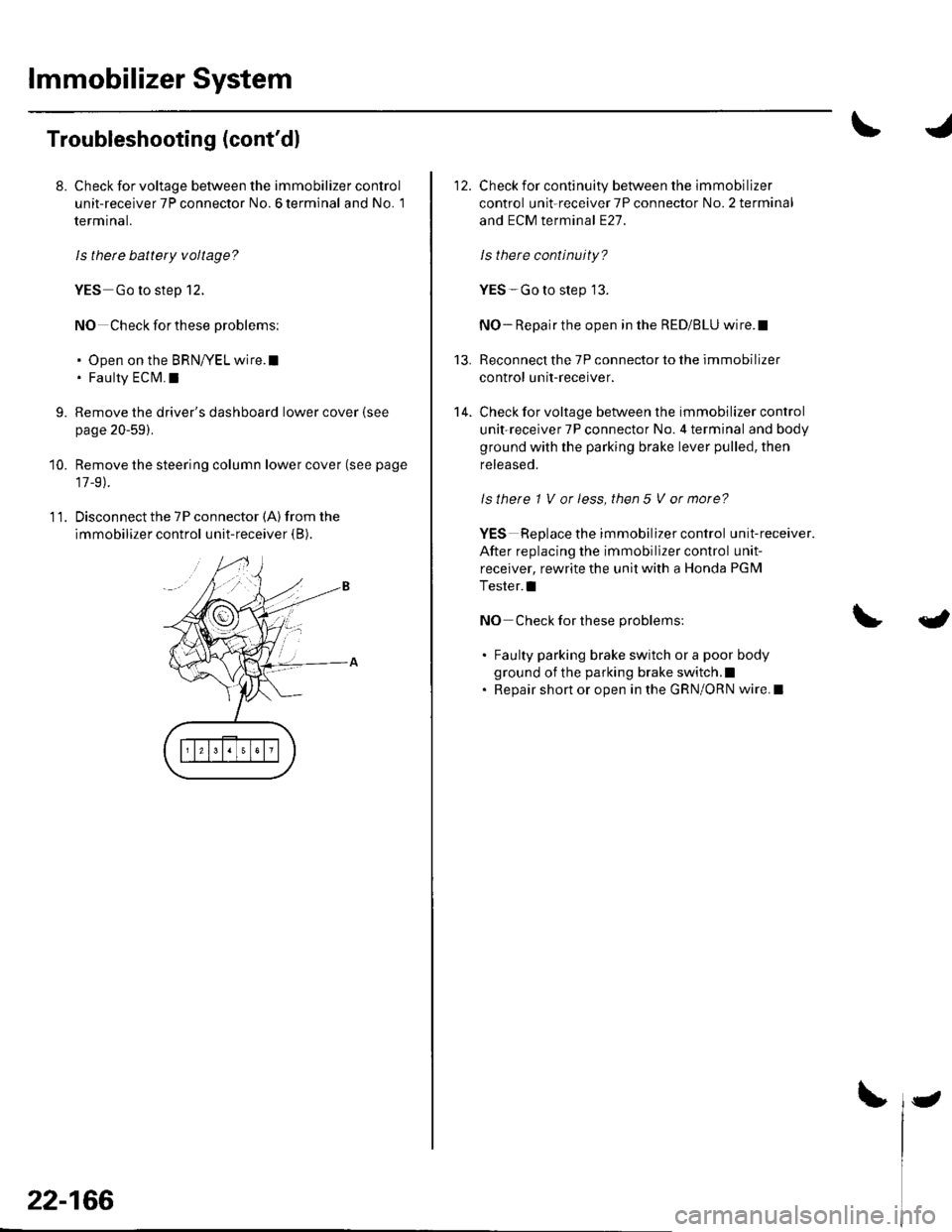
11. Disconnect the 7P connector (A) from the
immobilizer control unit-receiver (B).
22-166
-
Check for continuity between the immobilizer
control unit-receiver 7P connector No. 2 terminal
and ECM terminal E27.
ls there continuity?
YES-Go to step 13.
NO- Repair the open in the RED/BLU wire.I
Reconnect the 7P connector to the immobilizer
control unit-receiver.
Check for voltage between the immobilizer control
unit-receiver 7P connector No. 4 terminal and body
ground with the parking brake lever pulled, then
released.
ls there 1 V or less, then 5 V or more?
YES Replace the immobilizer control unit-receiver.
After replacing the immobillzer control unit-
receiver, rewrite the unit with a Honda PGM
Tester.l
NO Check for these problems:
. Faulty parking brake switch or a poor body
ground of the parking brake switch.l. Repair short or open in the GRN/ORN wire. I
13.
14.
{
Page 999 of 1139
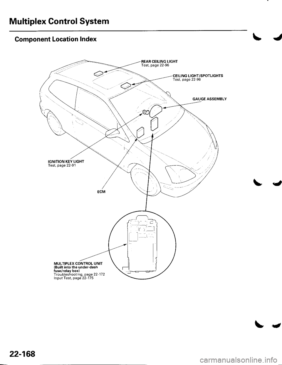
Multiplex Control System
Component Location Index
IGNITION KEY LIGHTTest, page 22'91
lr, J
REAR CEILING LIGHTTest, page 22'96
LIGHT/SPOTLIGHTSTest, page 22-96
GAUGE ASSEMBLY
ECM
MULTIPLEX CONTROL UNIT{Built into the under-dashfus6/relav boxlTroubleshooting, page 22'172Input Test, page 22-175
22-168
t
Page 1002 of 1139
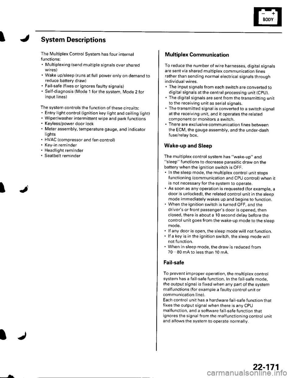
ISystem Descriptions
The Multiplex Control System has four internal
functions:. Multiplexing (send multiple signals over sharedwtres). Wake up/sleep (runs at full power only on demand toreduce battery draw). Fail-safe (fixes or ignores faulty signals). Self-diagnosis (Mode 1 for the system, Mode 2 for
input lines)
The system controls the function of these circuits:. Entry lightcontrol (ignition key lightandceiting light). Wiper/washer intermittent wipe and park functions. Keyless/power door lock. Meter assembly, temperature gauge, and indicator
lights. HVAC (compressor and fan control). Key-in reminder. Headlight reminder. Seatbelt reminder
JI
/ar
22-171
Multiplex Communication
To reduce the number of wire harnesses, digital signals
are sent via shared multiplex communication linesrather than sending normal electrical signals throughindividual wires.. The input signals from each switch are converted todigital signals at the central processing unit (CpU).. The digital signalsaresentfromthetransmitting unitto the receiving unit as serial signals.. The transmitted signal is converted to a switch signalat the receiving unit, and it operates the related
component or monitors a swltch.. There are exclusive communicalion lines between
the ECM, the gauge assembly, and the under,dash
fuse/relay box.
Wake-up and Sleep
The multiplex control system has "wake-up" and"sleep" functions to decrease parasitic draw on the
battery when the ignition switch is OFF.. ln the sleep mode, the multiplex control unit stops
functioning (communication and CPU control) when it
is not necessary for the system to operate.. As soon as any operation is requested (for example, adoor is unlocked), the related control unit in the sleep
mode immediately wakes up and begins to function.. When the ignition switch is turned OFF, and the
driver's or front passenger's door is opened, then
closed, there is about a 10 second delay before the
control unit goes from the wake-up mode to the sleepmode.. lf any door is open, the sleep mode will not function.. lf a key is in the ignition switch, the sleep mode will
not function.. When in sleep mode, the draw is reduced from
70 80 mA to less than 10 mA.
Fail-safe
To prevent improper operation, the multiplex controlsystem has a fail-safe function. In the fail-safe mode,
the output signal js fixed when any part of the systemmalfunctions (for example a faulty control unit orcommunication line).
Each control unit has a hardware fail-safe function thatfixes the output signal when there is any CPUmalfunction, and a software fail-safe function thatignores the signal from the malfunctioning control unitand allows the system to operate normally.
Page 1004 of 1139
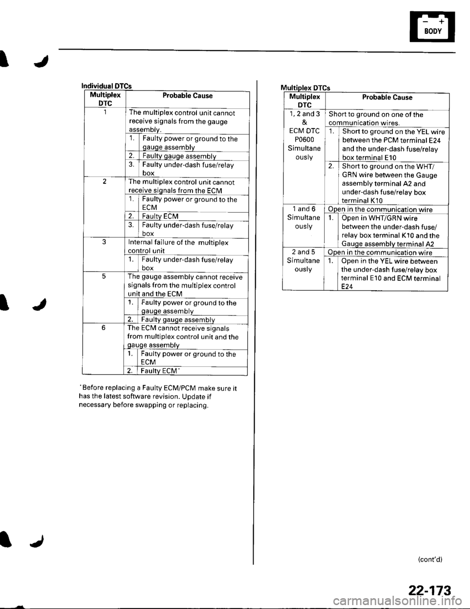
I
Individual
Multiplex
DTC
Probable Cause
The multiplex control unit cannot
receive signals from the gauge
assemDty.'lFaulty power or ground to thegauge assembly
2.Faulty gauge assemblv
3.Faulty under-dash f use/relay
box
The multiplex control unit cannot
receive signals from the ECM
1Faulty power or ground to the
ECM
2.Faulty ECM?Faulty under-dash fuse/relay
box
JInternal failure of the multiplex
control unit
1Faulty under-dash fuse/relay
box
5The gauge assembly cannot receive
signals from the multiplex control
unit and the ECM
Faulty power or ground to thegauge assembtv
Faulty qauge assemblv
6The ECM cannot receive signals
from multiplex control unit and thegauge assembty
1Faulty power or ground to the
ECM
Faulty ECM'
I
'Before replacing a Faulty ECM/PCM make sure ithas the latest software revision. UDdate if
necessary before swapping or replacing.
DTCs
Multiplex
DTC
Probable Cause
1,2 and 3
&
ECM DTC
P0600
Simultane
ously
Short to ground on one of the
communication wires.
Short to ground on the YEL wire
between the PCM terminal E24
and the under-dash fuse/relay
box terminal E10
2.Short to ground on the WHT/
GRN wire between the Gauge
assembly terminal A2 and
under-dash fuse/relay box
terminal K10
1and6
Simultane
ous ly
Open in the communication wire
IOpen in WHT/GRN wire
between the under-dash fuse/
relay box terminal K10 and the
Gauqe assemblV terminal 42
2and5
Simultane
ously
Open in the communication wire
1Open in the YEL wire between
the under-dash fuse/relay box
terminal E10 and ECM terminal
(cont'd)
22-173
Page 1013 of 1139
9.
10.
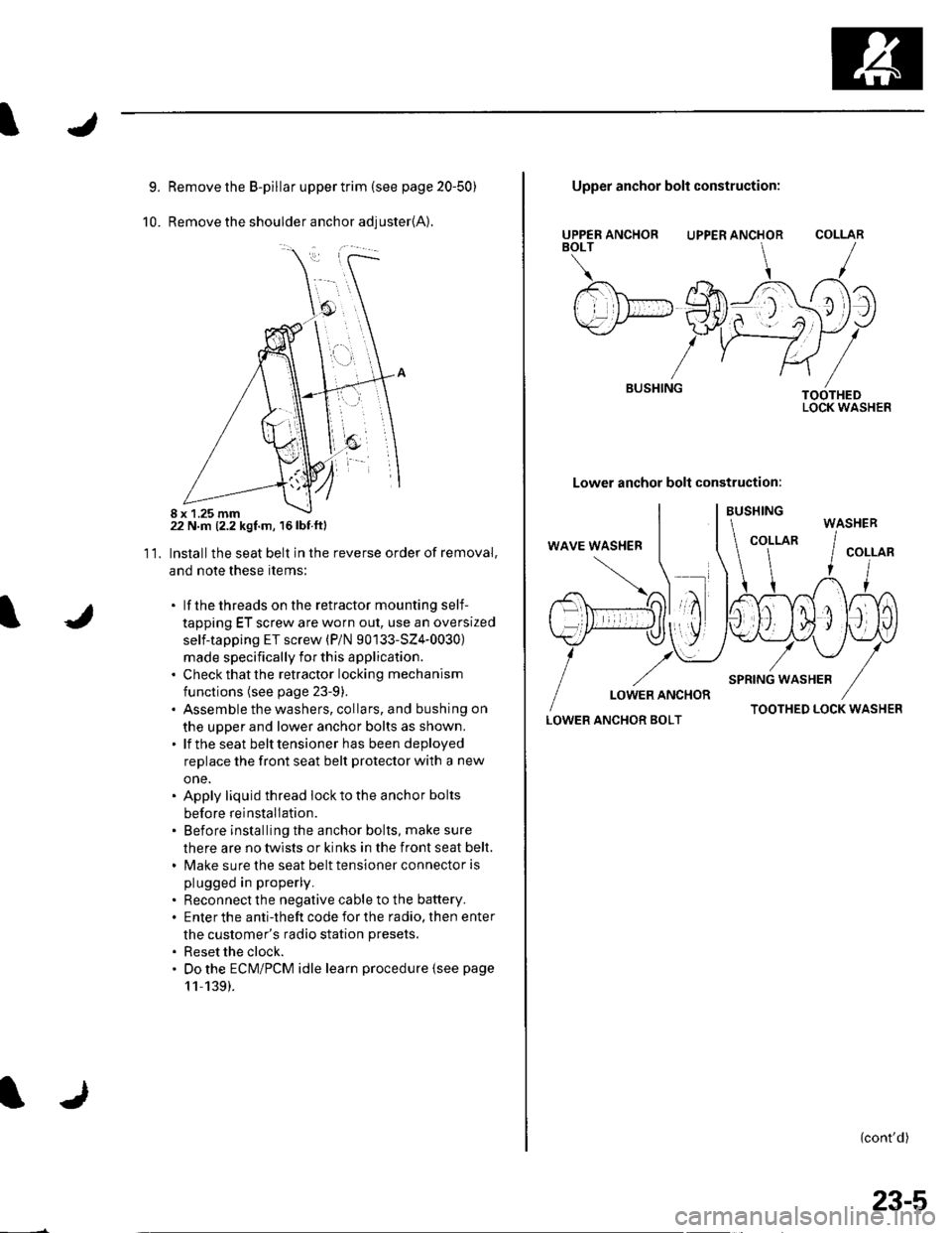
Remove the B-pillar upper trim {see page 20-50)
Remove the shoulder anchor adjuster{A).
22 N.m (2.2 kgf.m, 16lbf.ftl
Installthe seat belt in the reverse order of removal,
and note these items:
. lf thethreads on the retractor mounting self-
tapping ET screw are worn out, use an oversized
self-tapping ET screw (P/N 90133-SZ4-0030)
made specifically for this application.. Check that the retractor locking mechanism
functions (see page 23-9).. Assemble the washers, collars, and bushing on
the upper and lower anchor bolts as shown.. lf the seat belt tensioner has been deployed
replace the front seat belt protector with a new
one.. Apply liquid thread lock to the anchor bolts
before reinstallation.. Before installing the anchor bolts, make sure
there are no twists or kinks in the front seat belt.. Make sure the seat belt tensioner connector is
plugged in properly.
. Reconnect the negative cable to the battery.. Enter the anti-theft code for the radio, then enter
the customer's radio station presets.
. Reset the clock.. Do the ECM/PCM idle learn procedure {see page
11,139).
11.
8 x 1.25 mm
UPPER ANCHORBOLT
BUSHING
Upper anchor bolt construction:
UPPER ANCHOR
Lower anchor bolt construction:
COLLAR
TOOTHEDLOCK WASHER
LOWER ANCHOR BOLTTOOTHED LOCK WASHER
{cont'd)
WASHER
23-5
Page 1014 of 1139
Seat Belts
Front Seat Belt Replacement (cont'd)
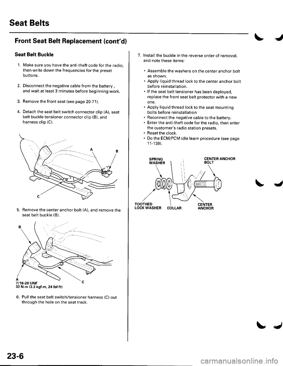
Seat Belt Buckle
1. Make sure you have the anti-theft code for the radio,
then write down the frequencies for the preset
buttons.
2. Disconnect the negative cable from the battery ,and wait at least 3 minutes before beginning work.
3. Remove the front seat (see page 20-7'1).
4. Detach the seat belt switch connector clip (A), seat
belt buckle tensioner connector clip (B), and
harness clip (C).
5. Remove the center anchor bolt (A), and remove the
seat belt buckle {B).
7/16-20 UNF32 N m {3.3 kgf m,24lbf.ft)
6. Pullthe seat belt switch/tensioner harness (C) out
through the hole on the seat track.
. -.. :.a--
23-6
7. Installthe buckle in the reverse order of removal,
and note these items:
. Assemble the washers on the center anchor bolt
as shown.. Apply liquid thread lock to the center anchor bolt
before reinstallation.. lf the seat belt tensioner has been deployed,
replace the front seat belt protector with a new
one.. Apply liquid thread lock to the seat mounting
bolts before reinstallation. Reconnect the negative cable to the battery.. Enter the anti-theft code for the radio, then enter
the customer's radio station presets.. Reset the clock.. Do the ECMiPCM idle learn procedure (see page
1 1_139).
COLLAR
Page 1021 of 1139
sRs
Precautions and Procedures
General Precautions
Please read the following precautions carefully beforeperforming airbag system service. Observe theinstructions described in this manual. or the airbags
could accidentally deploy and cause damage or injuries.
. Except when performing electrical inspections.
always turn the ignition switch OFF, disconnect the
negative cable from the battery, and wait at least 3minutes before beginning work.
NOTE: The memory is not erased even if the ignition
switch is turned OFF or the battery cables are
disconnected from the battery.. Use replacement pans which are manufactured to the
same standards and quality as the original parts. Do
not install used SRS parts from another vehicle. Useonly new pans when making SRS repairs.. Carefully inspect any SRS part before you install it.
Do not install any part that shows signs of being
dropped or improperly handled, such as dents, cracks,
or deformation.
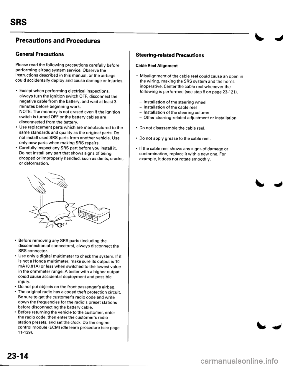
. Before removing any SRS parts (including the
disconnection of connectors), always disconnect the
SRS connector.. Use only a digital multimeter to check the system. lf itis not a Honda multimeter, make sure its outout is 10mA (0.01A) or less when switched to the lowest value
in the ohmmeter range. A tester with a higher output
could cause accidental deployment and possible
injury.. Do not put objects on the front passenger's airbag.. The original radio has a coded theft protection circuit.
Be sure to get the customer's radio code and write
down the frequencies for the radio's preset stations
before disconnecting the battery cable.. Before returning the vehicle to the customer, enter
the radio code. then enter the customer's radio
station presets, and set the clock. Do the engine
control module (ECM) idle learn procedure (see page
11-139).
23-14
c
Steering-related Plecautions
Cable Reel Alignment
. Misalignment of the cable reel could cause an open in
the wiring, making the SRS system and the horns
inoperative. Center the cable reel whenever the
following is performed (see step 6 on page 23-121).
- Installation of the steering wheel- Installation of the cable reel- Installation ofthe steering column- Other steering-related adjustment or installation
. Do not disassemble the cable reel.
. Do not apply grease to the cable reel.
. lf the cable reel shows any signs of damage or
contamination. replace it with a new one. For
example, it does not rotate smoothly.