Radio HONDA CIVIC 2003 7.G User Guide
[x] Cancel search | Manufacturer: HONDA, Model Year: 2003, Model line: CIVIC, Model: HONDA CIVIC 2003 7.GPages: 1139, PDF Size: 28.19 MB
Page 501 of 1139
T
\
Steering Column Removal and Installation
SRS components are located in this area. Review the SRS component locations (see page 23-13) and precautions andprocedures (see page 23-14) in the SRS section before performing repairs or service.
Removal
1, Record the radio station presets, and disconnect the battery.
2. Removethedriver'sairbagassembly(seepage23-113) and the steering wheel (see page 17-6).
3. Removethe driver's dashboard lowercover(see page 20-59) and undercover(see page 20-60).
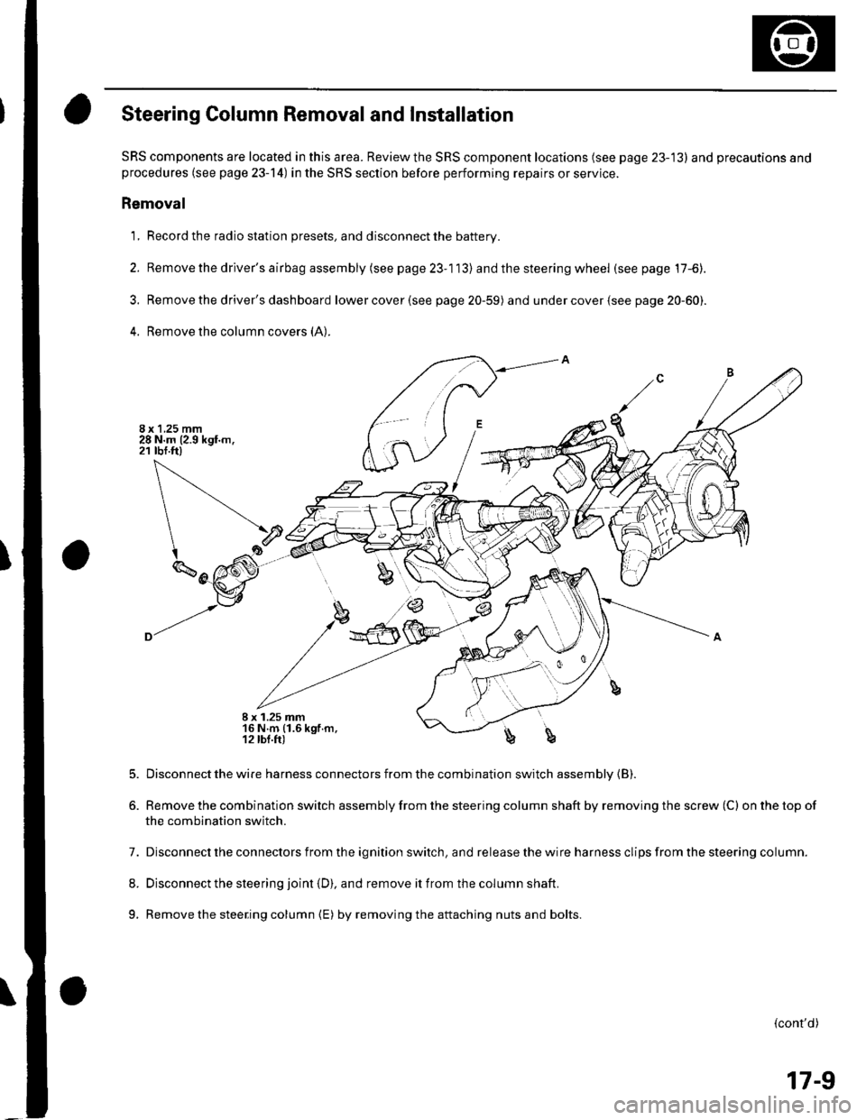
4. Remove the column covers (A:
I x 1.25 mm16 N.m (1.6 kgf.m,12 lbl.fr)b
5.
6.
Disconnect the wire harness connectors from the combination switch assembly {B).
Remove the combination switch assembly from the steering column shaft by removing the screw (C) on the top of
the combination switch.
7. Disconnect the connectors from the ignition switch, and release the wire harness clips from the steering column.
8. Disconnect the steering joint (D), and remove it from the column shaft.
9. Remove the steering column {E) by removingthe attaching nuts and bolts.
(cont'd)
17-9
Page 502 of 1139
Steering
Steering Column Removal
lnstallation
1.
4.
Install the steering column, and make sure the
wires are not caught or pinched by any parts.
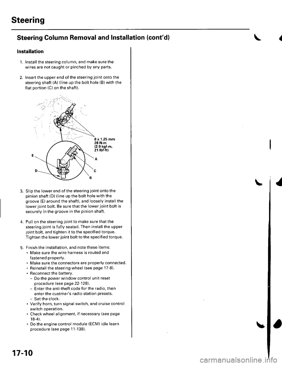
Insertthe upper end ofthe steering joint onto the
steering shaft {A) (line up the bolt hole (B) with the
flat portion (C) on the shaft).
8 x 1,25 mm28 N.m{2.9 kgf m,21 rbr.ft)
A
Slip the lower end of the steering joint onto the
pinion shaft {D) (line up the bolt hole with the
groove (E) around the shaft), and loosely lnstallthe
lower joint bolt. Be sure that the lower joint bolt is
securely in the groove in the pinion shaft.
Pull on the steering joint to make su re that the
steering joint is fully seated. Then installthe upper
joint bolt, and tighten it to the specified torque.
Tighten the lower joint bolt to the specified torque.
Finish the installation, and note these items:
. Make sure the wire harness is routed and
fastened properly.
. Make sure the connectors are properly connected.. Reinstallthe steering wheel (see page 17-8).
. Reconnect the battery.- Do the power window control unitreset
procedure {see page 22-128).- Enter the anti-theft code for the radio, then
enter the custmer's radio station presets.
- Set the clock.. Verify horn, turn signal switch, and cruise control
switch operation.. Check wheel alignment, if necessary (see page
18-4).. Do the engine control module (ECM) idle learn
procedu re {see page '11-139).
17-10
and Installation (cont'd){
Page 540 of 1139
Motor Removal/lnstallation
Bemoval
1. Make sure you have the anti-theft code for the radio,
then write down the frequencies for the preset
buttons.
2. Disconnect the negative cable from the battery, and
wait 3 minutes before beginning work.
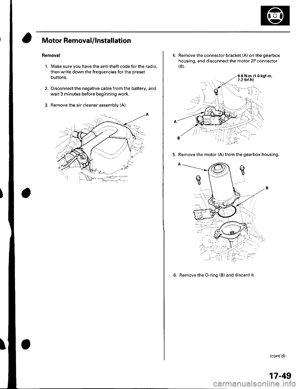
3. Remove the air cleaner assembly (A).
4. Remove the connector bracket (A) onthegearbox
housing, and disconnect the motor 2P connector(B).
9.8 N.m {1.0 kgf.m,
5. Remove the motor {A) from the gearbox housing.
6. Remove the O-ring (B) and discard it.
(cont'd)
17-49
Page 541 of 1139
EPS Components
(Motor RemovaUlnstallation (cont'dl
lnsiallation
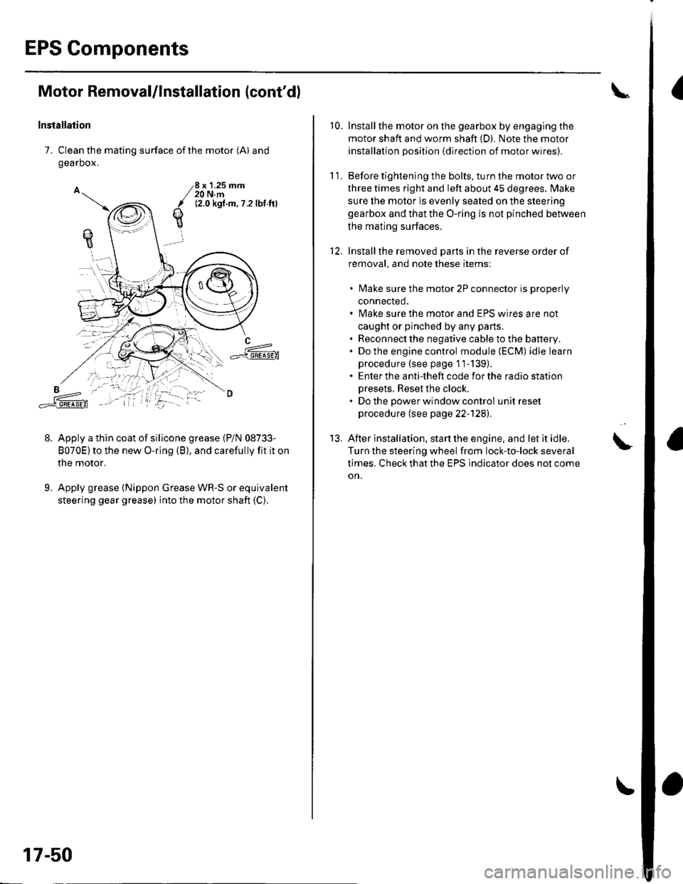
7. Clean the mating surface of the motor (A) and
gearbox.
Apply a thin coat of silicone grease (P/N 08733-
8070E)to the new O-ring (B), and carefully fit it on
the motor.
Apply grease {Nippon Grease WR-S or equivalent
steering gear grease) into the motor shaft (C).
qE
8 x '1.25 mm20 N.m12.0 kgt.m,7 .2lbl ftl
L==-c].E@
9.
17-50
r0.Install the motor on the gearbox by engaging the
motor shaft and worm shaft (D). Note the motor
installation position {direction of motor wires).
Before tightening the bolts, turn the motor two or
three times right and left about 45 degrees. lvlake
sure the motor is evenly seated on the steering
gearbox and that the O-ring is not pinched betlveen
the mating surfaces.
Installthe removed Darts in the reverse order of
removal. and note these items:
lvlake sure the motor 2P connector is properly
connected.
lvlake sure the motor and EPS wires are not
caught or pinched by any parts.
Reconnect the negative cable to the battery.
Do the engine control module (ECM) idle learn
procedure (see page 11-139).
Enter the anti-theft code for the radio station
Dresets. Reset the clock,
Do the oower window control unit reset
procedure (see page 22-1241.
After installation, start the engine, and let it idle.
Turn the steering wheel from lock-to-lock several
times. Check that the EPS indicator does not come
on.
11.
12.
13.
Page 716 of 1139
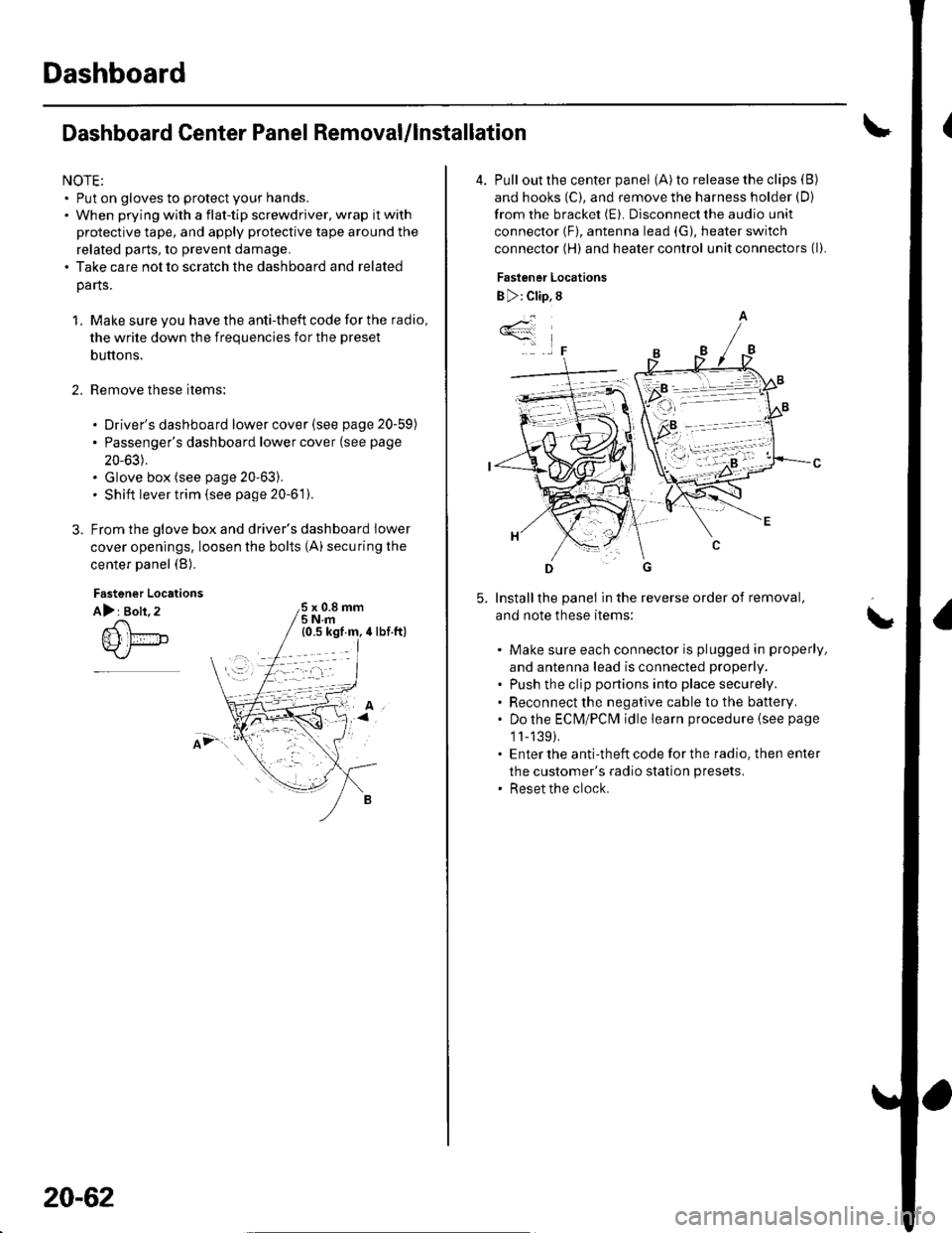
Dashboard
Dashboard Center Panel Removal/lnstallation
NOTE:. Put on gloves to protect your hands.. When prying with a flat-tip screwdriver, wrap it with
protective tape, and apply protective tape around the
related parts, to prevent damage.. Take care not to scratch the dashboard and related
parts.
1. Make sure you have the anti-theft code for the radio,
the write down the frequencies for the preset
buttons.
Remove these items:
. Driver's dashboard lower cover (see page 20-59)
. Passenger's dashboard lower cover (see page
20-63).. Glove box (see page 20-63).. Shift lever trim {see page 20-61).
From the glove box and driver's dashboard Iower
cover openings, loosen the bolts (A) securing the
center panel (B).
2.
Fastener Locations
A): Bolt, 2x 0.8 mm5Nm
;.'
20-62
4. Pull out the center panel (A) to release the clips (B)
and hooks (C), and remove the harness holder (D)
from the bracket (E). Disconnect the audio unit
connector (F), antenna lead (G), heater switch
connector (H) and heater control unit connectors (l).
Fastener Locations
B ): Clip, 8
Installthe panel in the reverse order of removal,
and note these items:
Make sure each connector is plugged in properly,
and antenna lead is connected properly.
Push the clip portions into place securely.
Reconnect the negative cable to the battery.
Do the ECN4/PCt\4 idle learn procedure {see page
1l-139).
Enter the anti-theft code for the radio. then enter
the customer's radio station presets.
Reset the clock.
*4
,F
\
Page 720 of 1139
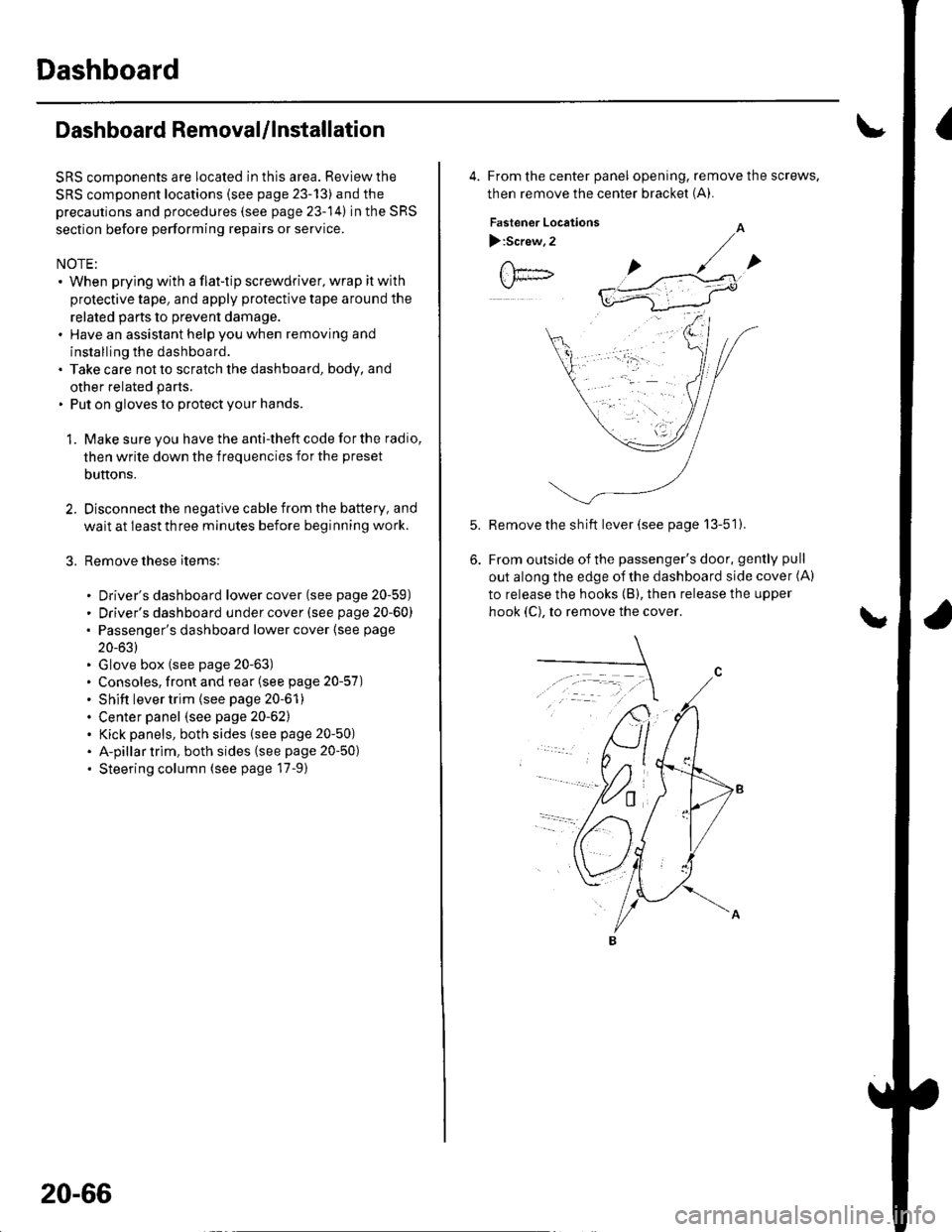
Dashboard
Dashboard Removal/lnstallation
SRS components are located in this area. Review the
SRS component locations (see page 23-13) and the
precautions and procedures (see page 23-14) in the SRS
section before performing repairs or service.
NOTE:. When prying with a flat-tip screwdriver, wrap it with
protective tape, and apply protective tape around the
related parts to prevent damage.. Have an assistant help you when removing and
installing the dashboa rd.. Take care not to scratch the dashboard, body, and
other related parts.
. Put on gloves to protect your hands.
1. Make sure you have the anti-theft code for the radio,
then write down the frequencies for the preset
buttons.
Disconnect the negative cable from the battery, and
wait at least three minutes before beginning work.
Remove these items:
. Driver's dashboard lower cover (see page 20-59). Driver's dashboard under cover (see page 20-60). Passenger's dashboard lower cover (see page
20-63). Glove box (see page 20-63). Consoles, front and rear (see page 20-57). Shift lever trim {see page 20-61). Center panel (see page 20-62). Kick panels, both sides (see page 20-50). A-pillar trim. both sides (see page 20-50). Steering column (see page 17-9)
20-66
4. From the center panel opening, remove the screws,
then remove the center bracket (A).
Fastener Locations
):Screw,2
Remove the sh ift lever (see page 13-51).
From outside of the passenger's door, gently pull
out along the edge of the dashboard side cover (A)
to release the hooks (B), then release the upper
hook (C), to remove the cover.
Page 722 of 1139
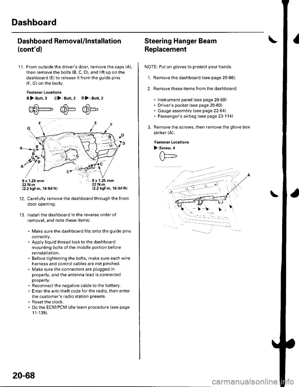
Dashboard
Dashboard Removal/lnstallation
(cont'd)
11. From outside the driver's door, remove the caps (A),
then remove the bolts (8, C, D), and lift up on the
dashboard (E) to release it from the guide pins
(F. G) on the body.
Fastener Locations
B>rBolt.3 C>: Bolt,2 D>: Bolt,2
m6[-,,,,",",,-,F6't---'' ffi'!--v{/- Kr* w-
B
$7:
^/761:
/,-,. r:; 8 x 1.25 mm22Nm(2.2 kgf.m, 16lbf.ft)
13.
{2.2 kgf m, 16lbf.ftl
Carefully remove the dashboard through the front
door opening.
lnstall the dashboard in the reverse order of
removal, and note these items:
. Make sure the dashboard fits onto the guide pins
correctly.. Apply liquid thread lock to the dashboard
mounting bolts of the middle portion before
reinstallation.. Before tightening the bolts, make sure each wire
harness and control cables are not pinched.
. Make sure the connectors are plugged in
properly, and the antenna lead is connected
propeny.. Reconnect the negative cable to the battery.. Enter the anti-theft code for the radio, then enter
the customer's radio station presets.
. Reset the clock.. Do the ECM/PCM idle learn procedure isee page
1 '1-139).
20-68
Steering Hanger Beam
Replacement
NOTE: Put on gloves to protect your hands.
1, Remove the dashboard (see page 20-66).
2. Remove these items from the dashboard:
. lnstrument panel (see page 20-59). Driver's pocket (see page 20-60). Gauge assembly (see page 22-64). Passenger's airbag (see page 23-'l 14)
Remove the screws, then remove the glove box
striker (A).
Fastenea Locations
):Screw,4
\
Page 725 of 1139
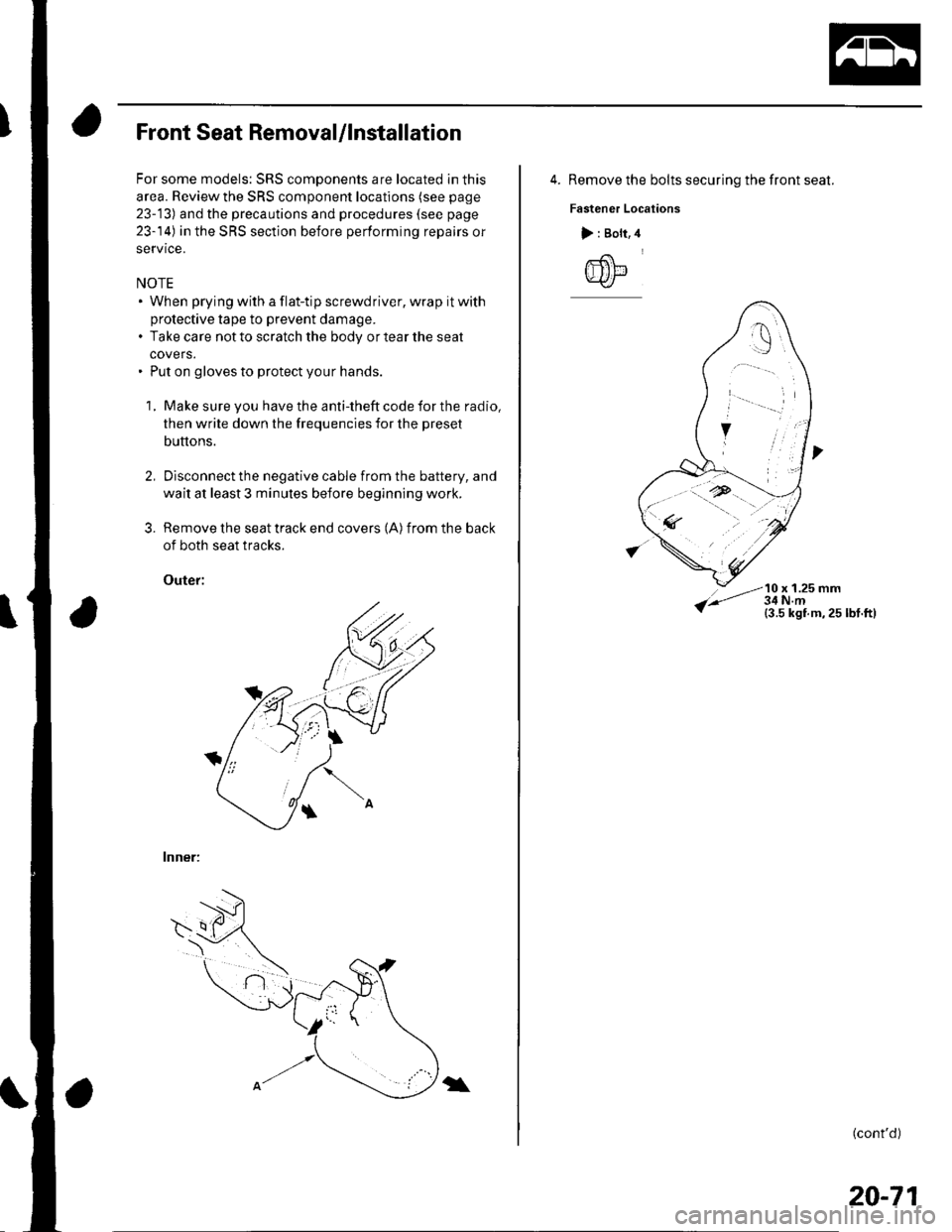
Front Seat Removal/lnstallation
For some models: SRS components are located in this
area. Review the SRS component locations (see page
23-'13) and the precautions and procedures (see page
23-14) in the SRS section before performing repairs or
service.
NOTE. When prying with a flat-tip screwdriver, wrap it with
protective tape to prevent damage.. Take care not to scratch the body or tear the seat
covers.. Put on gloves to protect your hands.
1, Make sure you have the anti-theft code for the radio,
then write down the frequencies for the preset
butlons.
Disconnect the negative cable from the battery, and
wait at least 3 minutes before beginning work.
Remove the seat track end covers (A) from the back
of both seat tracks.
Outef:
lnner:
3.
\
4. Remove the bolts securing the front seat.
Fastener Locations
10 x 1.25 mm
> : Bolt,
@
(cont'd)
20-71
Page 726 of 1139
Seats
Front Seat Removal/lnstallation (cont'dl
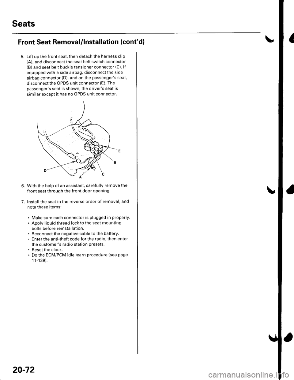
Lift up the front seat, then detach the harness clip(A). and disconnect the seat belt switch connector(B) and seat belt buckle tensioner connector (C). lf
equipped with a side airbag, disconnect the side
airbag connector (D), and on the passenger's seat,
disconnect the OPDS unit connector (E). The
passenger's seat is shown, the driver's seat is
similar except it has no OPDS unit connector.
With the help of an assistant, carefully remove the
front seat th rough the front door opening.
Installthe seat in the reverse order of removal, and
note these rtems:
. l\4ake sure each connector is plugged in properly.
. Apply liquid thread lock to the seat mounting
bolts before reinstallatlon.. Reconnect the negative cable to the battery.. Enter the anti-theft code for the radio, then enter
the customer's radio station presets.
. Reset the clock.. Do the ECM/PCM idle learn procedure (see page
1 1-139).
6.
7.
20-72
Page 810 of 1139
Dust and Pollen Filter Replacement
The dust and pollen filters should be replaced every
30,000 miles (48.000 km) or 24 months whichever
comes first. Replace the filters more often if the air flow
is less than usual.
1. Open the glove box. Remove both glove box stops,
then let the glove box hang down (see page 20 63).
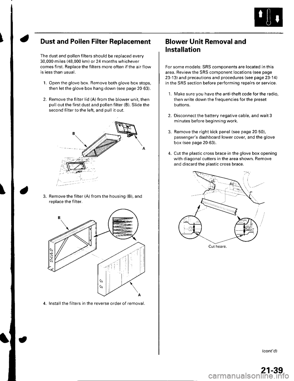
2. Remove the filter lid (A)from the blower unit, then
pull out the first dust and pollen filter (B). Slide the
second filter to the left, and pull it out.
Remove the filter {A) from the housing (B), and
replace the filter.
4. Install the filters in the reverse order of removal.
Blower Unit Removal and
lnstallation
For some models: SRS components are located in this
area. Review the SRS component locations (see page
23-13) and precautions and procedures (see page 23-14)
in the SRS section before performing repairs or service.
1. Make sure you have the anti-theft code for the radio,
then write down the frequencies for the preset
buttons.
2. Disconnect the battery negative cable, and wait 3
minutes before beginning worK.
3. Remove the right kick panel (see page 20-50),
passenger's dashboard lower cover, and the glove
box {see page 20-63).
4. Cut the plastic cross brace in the glove box opening
with diagonal cutters in the area shown. Remove
and discard the plastic cross brace,
Cut heare.
{cont'd)
21-39