dashboard HONDA CIVIC 2003 7.G User Guide
[x] Cancel search | Manufacturer: HONDA, Model Year: 2003, Model line: CIVIC, Model: HONDA CIVIC 2003 7.GPages: 1139, PDF Size: 28.19 MB
Page 627 of 1139
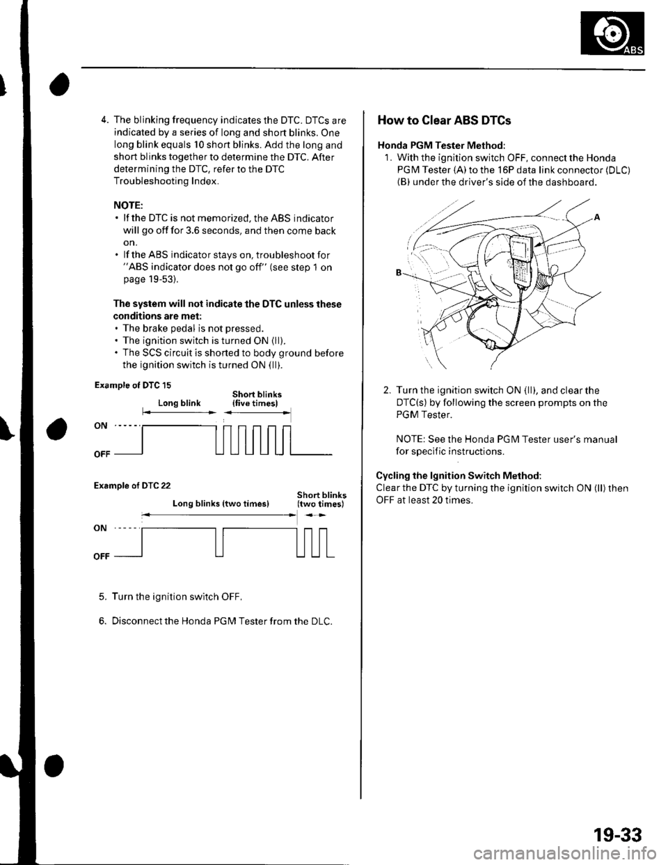
4. The blinking frequency indicates the DTC. DTCS are
indicated by a series of long and short blinks. One
long blink equals 10 shon blinks. Add the long and
short blinks together to determine the DTC. After
determining the DTC, refer to the DTC
Troubleshooting Index.
NOTE:. lf the DTC is not memorized, the ABS indicator
will go off for 3.6 seconds, and then come back
on.. lf the ABS indicatorstays on, troubleshootfor"ABS indicator does not go off" (see step 1 onpage 19-53).
Th€ system will not indicate the DTC unless these
conditions are met:. The brake pedal is not pressed.. The ignition switch is turned ON {ll).. The SCS circuit is shorted to body ground before
the ignition switch is turned ON (ll).
Example ot DTC 15
Long blinkShort blinks{five timesl
Examole of DTC 22
Long blinks (two times)
Turn the ignition swltch OFF,
Disconnect the Honda PG M Tester from the DLC.
5.
How to Clear ABS DTCs
Honda PGM Tester Method:
1. With the ignition switch OFF, connect the Honda
PGM Tester (A)to the l6Pdata link connector (DLC)
{B} under the driver's side of the dashboard.
Turn the ignition switch ON (ll), and clearthe
DTC(s) by following the screen prompts on the
PGM Tester.
NOTE: See the Honda PG l\4 Tester user's manual
for sDeclf ic instructions.
Cycling the lgnition Switch Method:
Clear the DTC by turning the ignition switch ON (ll) then
OFF at least 20 times.
19-33
Page 654 of 1139
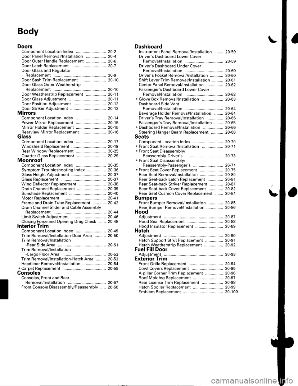
Body
DoorsComponent Location Index ...........Door Panel Removal/lnstallation .....,..........Door Outer Handle ReplacementDoor Latch ReplacementDoor Glass and RegulatorReplacementDoor Sash Trim Replacement .......................
Door Glass Outer WeatherstripReplacement
Door Weatherstrip Beplacement
Door Glass Adjustment .................................Door Position Adjustment .............................Door Striker Adiustment ................................MirrorsComponent Location Index ...........................Power Mirror Replacement ...........................Mirror Holder Replacement ...........................Rearview Mirror Rep1acement ......................
GlassComponent Location Index ...........................Windshield Replacement
Bear Window Rep1acement ...........................
Ouarter Glass Replacement ..........................MoonroofComponent Location Index ...........................Symptom Troubleshooting Index
Glass Height Adjustment ...............................
Glass ReplacementWind Def lector 8ep1acement ........................Drain Channel Rep1acement ..........................Sunshade Replacement .................................Motor ReplacementFrame and Drain Tube Replacement ............Drain Channel Slider and Cable AssemblyReplacementLimit Switch Adjustment ...............................Closino Force and ODenina Draq Check ......lnterioi TrimComponent Location Index ...........................Trim Removal/lnstallation DoorArea ..........Trim Removal/lnstallation-Rear Side AreaTrim Removal/lnstallation-Cargo Floor AreaTrim Removal/lnstallation-Hatch Area .........Headliner Removal/lnstallation* Carpet Rep1acement .......................................ConsolesConsoles, Front and RearRemova l/lnsta llationFront Console Disassembly/Reassembly .....
20-220,420-620-7
20-920 t0
20- 10
20-1120-1120-1220 13
20-1420-1520-1520-16
20 1120-1920-2520-29
20,3520-3620-3720-3120-3820 3920-4020-4120,42
20 4420-4620,44
20-4920 50
20-51
DashboardInstrument Panel Removal/lnstallation ........Driver's Dashboard Lower CoverRemovat InstallationDriver's Dashboard Under CoverRemova t Insta llation
Oriver's Pocket Removal/lnstallation ............Shift Lever Trim Removal/lnstallation ..........Center Panel Removal/lnstallation ...............Passenger's Dashboard Lower CoverRemova l/lnsta llat ionx Glove Box Removal/lnstallationDashboard Side VentRemoval/lnstallation .................................. 20-64Beverage Holder Removal/lnstallation ........ 20-64Driver'sTray Removal/lnstallation ............... 20-65Passenger's Tray Removal/lnstallation ........ 20 65* Dashboard Removal/lnstallation .................. 20-66Steerinq Hanqer Beam Reolacement ........... 20-68Seats "
Component Location Index ........................... 20-10* Front Seat Removal/lnstallation ................... 20-11* Front Seat Disassembly/Reassembly-Driver's .................................. 20-73* Front Seat Disassembly/Reassembly-Passenger's ........................... 20-74* Front Seat Cover Replacement ..................... 2O-75Rear Seat Removal/1nsta11ation ..................... 20-80Rear Seat-back Latch Replacement .............. 20-81Rear Seat-backStriker Replacement ............ 20-81
20-59
20-59
Rear Seat-back Cover Replacement ............. 20-82Rear Seat Cushion Cover Replacement ....... 20.84BumpersFront Bumper Removal/lnstallation .............Rear Bumoer Removal/lnstallation ...............HoodAdjustmentHood Seal ReplacementHood Insulator Rep1acement .........................Hatch
20-6020,6020 6120-62
20-63
20-63
20,8520-86
20-4720,8820,89
20-5220-5320-5420-55
20-5720-58
Adjustment ................... 20-90Hatch Suppon Strut Replacement ................ 20-91Hatch WeatherstriD Reo1acement ................. 20-92
Fuel Fill DoorAdiustment ................... 20-93Exterior TrimFront Grille Replacement ..............Cowl Covers Replac"rn""t .. . .....................A pillar Corner Trim Replacement ................Roof lMolding Replacement ...........................Rear License Trim ReplacementHatch Spoiler 8ep1acement ...........................Emblem Rep1acement .........................
20-9420-9520-9620-9720,9820-9920-100
Page 673 of 1139
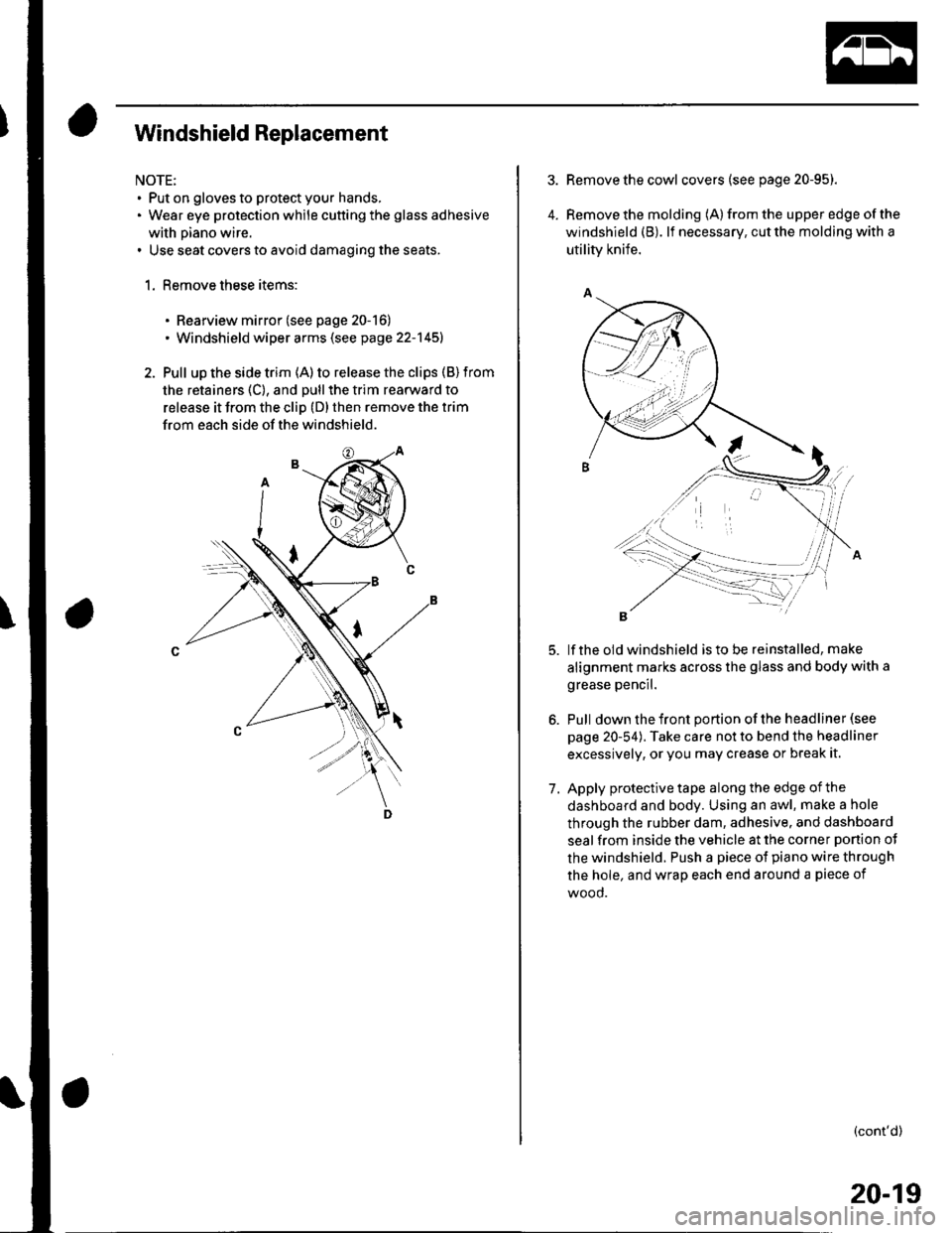
Windshield Replacement
NOTE:. Put on gloves to protect your hands,. Wear eye protection while cutting the glass adhesive
with piano wire.. Use seat covers to avoid damaging the seats.
1. Remove these items:
. Rearview mirror (see page 20-16). Windshield wiper arms (see page 22-145)
2. Pull up the side trim (A) to release the clips (B) from
the retainers (C), and pull the trim rearward to
release it from the cliD (D) then remove the trim
from each side of the windshield.
4.
Remove the cowl covers (see page 20-95).
Remove the molding (A) from the upper edge of the
windshield (B). lf necessary, cut the molding with a
utility knife.
lf the old windshield is to be reinstalled, make
alignment marks across the glass and body with a
grease pencil.
Pull down the front portion of the headliner (see
page 20-54). Take care not to bend the headliner
excessively, or you may crease or break it.
Apply protective tape along the edge of the
dashboard and body. Using an awl, make a hole
through the rubber dam, adhesive. and dashboard
seal from inside the vehicle at the corner ponion ot
the windshield. Push a piece of piano wire through
the hole, and wrap each end around a piece of
wood.
(cont'd)
7.
20-19
Page 674 of 1139
Glass
Windshield Replacement (cont'd)
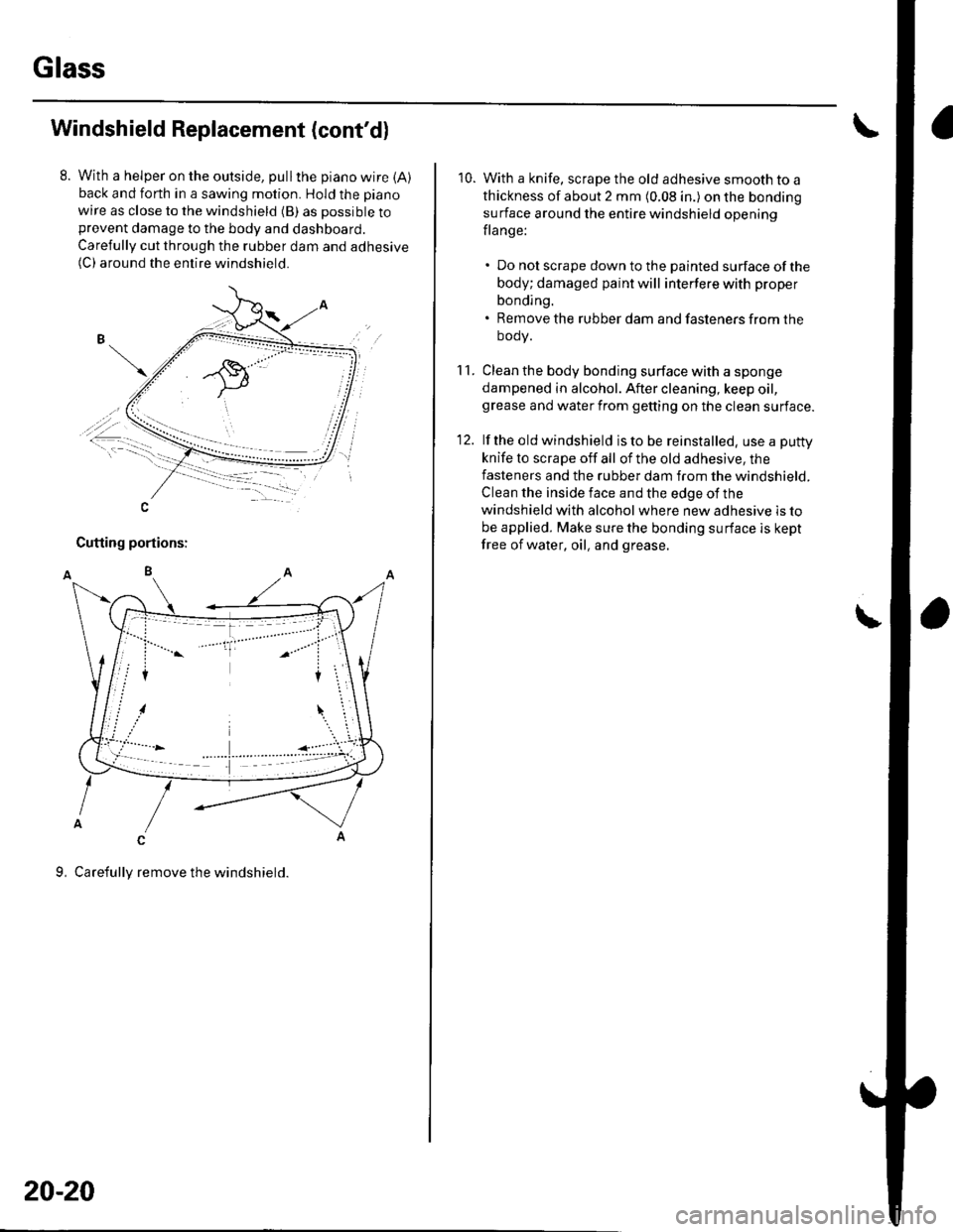
With a helper on the outside, pullthe piano wire {A)back and forth in a sawing motion. Hold the piano
wire as close to the windshield (B) as possible toprevent damage to the body and dashboard.
Carefully cut through the rubber dam and adhesive(C) around the entire windshield.
-A\, ,.-
,,t""""""""',-\i-.. -1:-, -
-=�-.--
20-20
10. With a knife, scrape the old adhesive smooth to a
thickness of about 2 mm (0.08 in.) on the bonding
surface around the entire windshield opening
flange:
. Do not scrape down to the painted surface ofthe
body; damaged paint will interfere with proper
bonding.. Remove the rubber dam and fasteners from the
oooy.
1 1. Clean the body bonding surface with a sponge
dampened in alcohol. After cleaning, keep oil,grease and water from getting on the clean surface.
12. lf the old windshield is to be reinstalled, use a puttv
knife to scrape off all of the old adhesive, the
fasteners and the rubber dam from the windshield.
Clean the inside face and the edge of the
windshield with alcohol where new adhesive is to
be applied. Make sure the bonding surface is kept
free of water, oil, and grease.
\
Page 677 of 1139
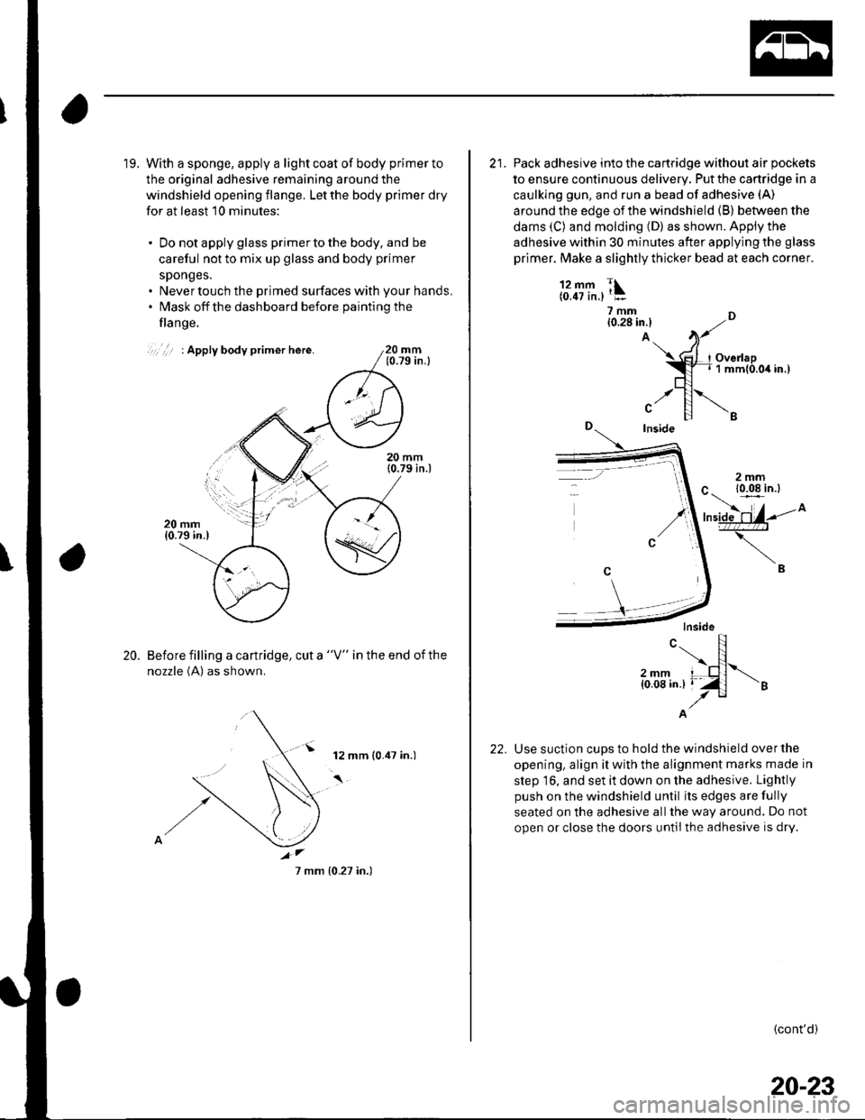
19. With a sponge, apply a light coat of body primer to
the original adhesive remaining around the
windshield opening flange, Let the body primer dry
for at least 10 minutes:
. Do not apply glass primer to the body, and be
careful not to mix up glass and body primer
sponges.. Never touch the primed surfaces with your hands.. l\4ask off the dashboard before paintingthe
flange.
20 mm(0.79 in.l
Before filling a cartridge, cut a "V" in the end of the
nozzle (A) as shown.
20.
12 mm (0.47 in.)
7 mm {0.27 in.)
21. Pack adhesive into the cartridge without air pockets
to ensure continuous delivery. Put the cartridge in a
caulking gun, and run a bead of adhesive (A)
around the edge of the windshield (B) between the
dams (C) and molding (D) as shown. Apply the
adhesive within 30 minutes after applying the glass
primer. Make a slightly thicker bead at each corner.
l'1fifr.,1:?mm n10.28 in.l ,..-A.. )t
$?I.",x1"u.80.".,trl
.,r []\"Inside
-'
A
Use suction cups to hold the windshield over the
opening, align it with the alignment marks made in
step 16, and set it down on the adhesive. Lightly
push on the windshield until its edges are fully
seated on the adhesive allthe way around. Do not
open or close the doors until the adhesive is dry.
c.. N\F12mm I nl{0.08 in.} I 'Z l
./"
(cont'd)
20-23
Page 708 of 1139
Interior Trim
Headliner RemovaUlnstallation
NOTE:. When prying with a flat-tip screwdriver, wrap itwith
protective tape to prevent damage.. Take care not to bend and scratch the headliner.. Be careful not to damage the dashboard and other
interior trim.
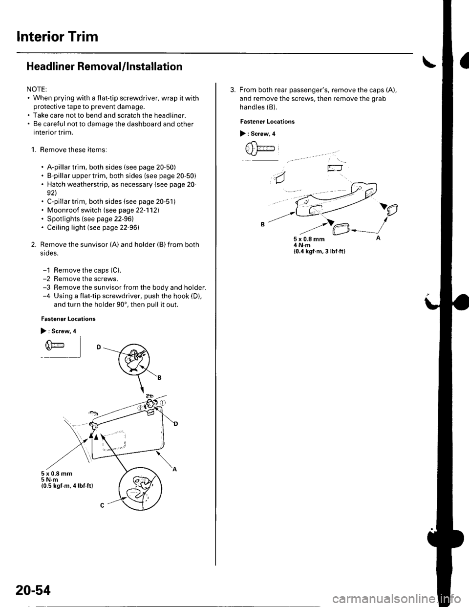
1. Remove these items:
. A-pillar trim, both sides (see page 20-50). B-pillar uppertrim, both sides (see page 20-50). Hatch weatherstrip, as necessary {see page 20-
92\. C-pillar trim, both sides (see page 20-51). Moonroof switch (see page 22-'112). Spotlights (see page 22-961. Ceiling light (see page 22-96)
Remove the sunvisor {A) and holder {B) from both
srdes.
-1 Remove the caps {C).-2 Remove the screws.-3 Remove the sunvisor from the body and holder.-4 Using a flat-tip screwdriver, push the hook (D),
and turn the holder 90'. then pull it out.
Fastener Locations
> : Screw, 4
r(\'-r)*
5x0.8mm5 N.m{0.5 kst m.4lbf ft}
20-54
3. From both rear passenger's, remove the caps (A),
and remove the screws, then remove the grab
handles (B).
Fastener Locations
> : Screw, 4
t , t;---iJ
)e
5x0.8mm4 N.m{0.4 kgf.m, 3 lbf.ft}
Page 709 of 1139
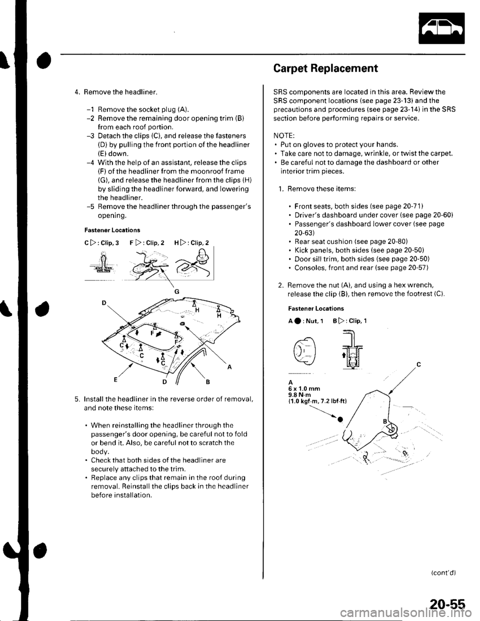
4. Remove the headliner.
-1 Remove the socket plug (A).
-2 Remove the remaining door opening trim {B}
from each roof portion.
-3 Detach the clips (C), and release the fasteners
(D) by pulling the front portion ofthe headliner
(E) down.-4 With the help of an assislant, release the clips(F) of the headliner from the moonroof frame
(G), and release the headliner from the clips (H)
by sliding the headliner forward, and lowering
the headliner.-5 Remove the headliner through the passenger's
opening.
Fastener Locations
C>:Clip,3
ao
5.Install the headliner in the reverse order of removal,
and note these items:
. When reinstalling the headliner through the
passenger's door opening, be careful not to fold
or bend it, Also, be careful not to scratch the
DOOy.. Check that both sides of the headliner are
securely attached to the trim.. Replace any clips that remain in the roof during
removal. Reinstallthe clips back in the headliner
before installation.
F>:Clip,2 H>:Clip,2
Carpet Replacement
SRS components are located in this area. Reviewthe
SRS component locations (see page 23-13) and the
precautions and procedures (see page 23-14) in the SRS
section before performing repairs or service.
NOTE:. Put on gloves to protect your hands.. Take care not to damage, wrinkle. or twist the carpet.. Be careful not to damage the dashboard or other
interior trim pieces.
1. Remove these items:
. Front seats, both sides (see page 20-111. Driver's dashboard under cover (see page 20-60). Passenger's dashboard Iower cover (see page
20-631. Rear seat cushion (see page 20-80). Kick panels, both sides (see page 20-50). Door silltrim, both sides (see page 20-50). Consoles, front and rear (see page 20-57)
2. Remove the nut (A), and using a hex wrench,
release the clip (B), then remove the footrest (C).
Fastener Locations
Aa:Nut,1 B):Clip,'l
--'1 I
-- -JrL
tj I ;tt4f=\-/ l[il
A6x1.0mm9.8Nm11.0 kgf m,7.2 lbf.ft)
-o
(cont'd)
20-55
Page 711 of 1139
Consoles
Console, Front and Rear Removal/lnstallation
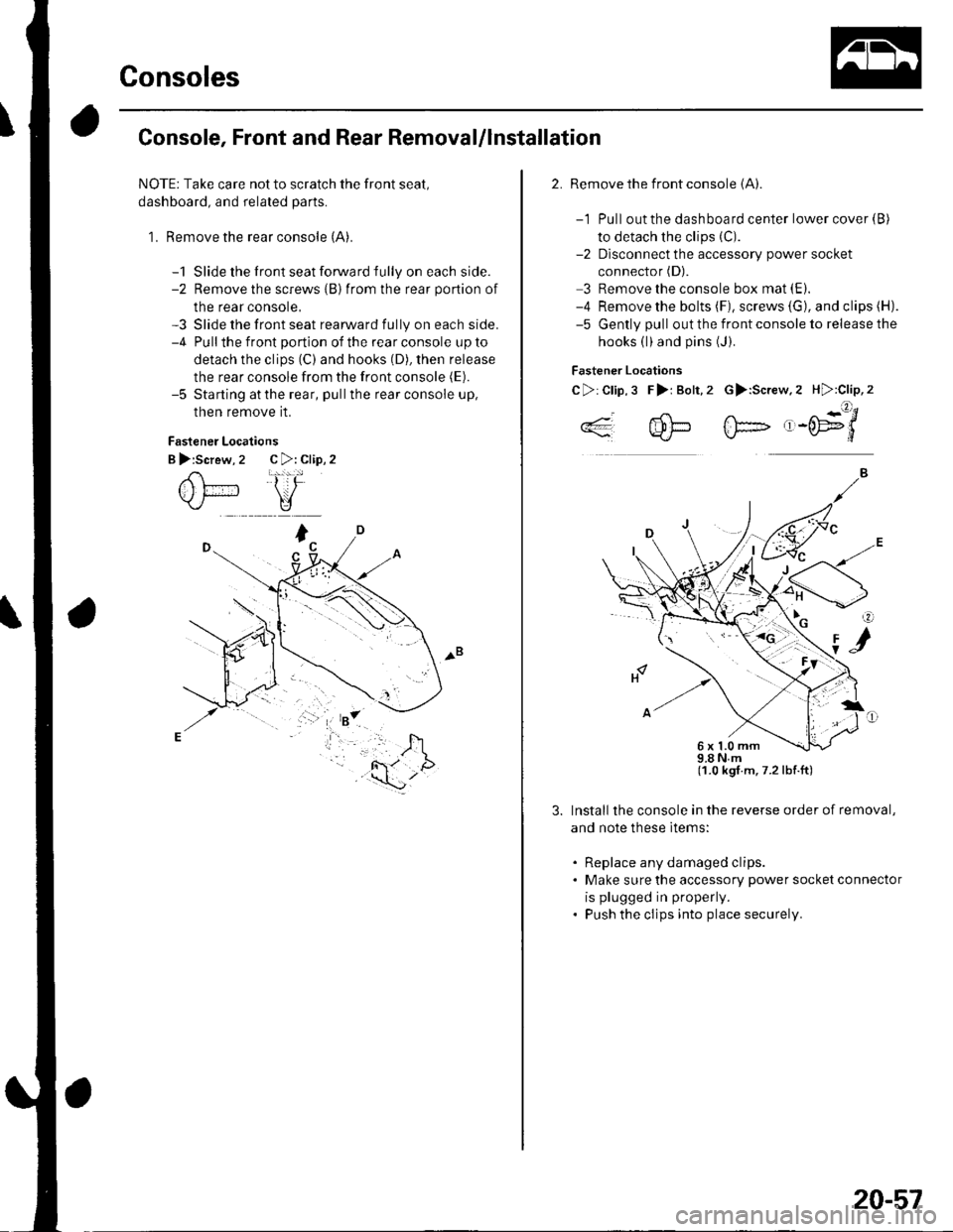
NOTE: Take care not to scratch the front seal,
dashboard, and related parts.
1. Remove the rear console (A).
-1 Slide the front seat forward fully on each side.-2 Remove the screws {B)from the rear portion of
the rear console,-3 Slide the front seat rearward fully on each side.-4 Pullthe front portion of the rear console up to
detach the clips (C) and hooks (D), then release
the rear console from the front console (E).
-5 Starting atthe rear, pullthe rear console up,
then remove it.
Fastener Locations
B >:Screw, 2 C >: Clip, 2
2. Remove the front console (A).
-1 Pull out the dashboard center lower cover {B)
to detach the clips (C).
-2 Dlsconnect the accessory power socket
connector (D).
3 Remove the console box mat (E).
-4 Remove the bolts (F), screws (G), and clips (H).
-5 Gently pull out the front console to release the
hooks (l)and pins (J).
Fastener Locations
C>:Clip,3 F>i Bolt,2 G>:Screw.2 H):Clip,2
..4- 4!-- fF- ,-('E9'/*'*q'J-L}*J\./-d
98Nm(1.0 kgt.m,7.2lbf.ft)
Install the console in the reverse order of removal,
and note these ltems:
. Replace any damaged clips.. Make sure the accessory power socket connector
is plugged in properly.
. Push the clips into place securely.
6x1.0mm
20-57
Page 713 of 1139
Dashboard
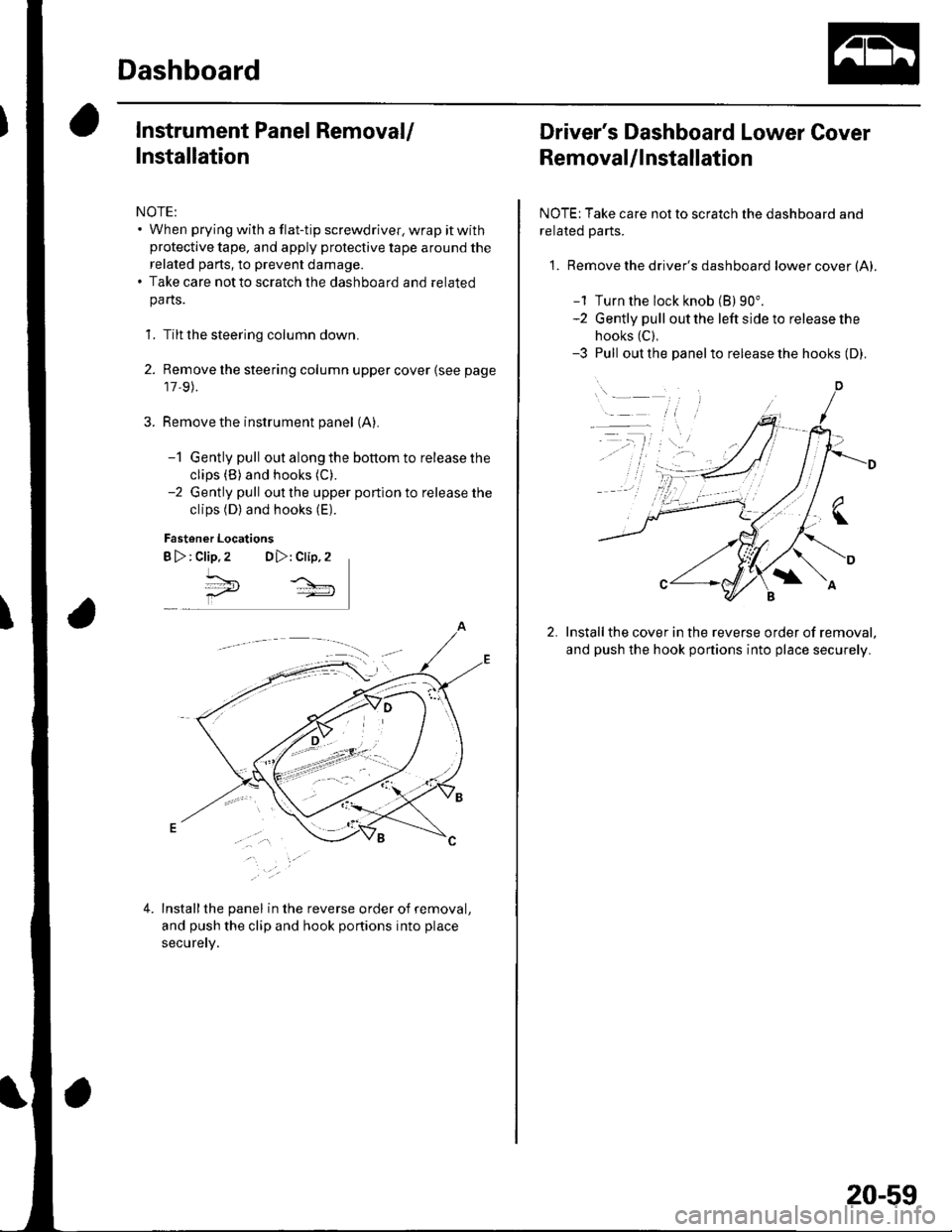
Instrument Panel Removal/
Installation
NOTE:. When prying with a flat-tip screwdriver, wrap it withprotective tape, and apply protective tape around the
related parts, to prevent damage.. Take care not to scratch the dashboard and related
pa rts.
1. Tilt the steering column down.
2. Remove the steering column upper cover {see page
17,9).
Remove the instrument panel (A).
-1 Gently pull out along the bottom to release the
clips (B) and hooks (C).
-2 Gently pull out the upper portion to release the
clips (D) and hooks (E).
Fastener Locations
B >: clip.2 DD,: Clip,2
^*,
4.Installthe panel in the reverse order of removal,
and push the clip and hook portions into place
securery.
Driver's Dashboard Lower Cover
Removal/lnstallation
NOTE: Take care not to scratch the dashboard and
related Parts.
1. Remove the driver's dashboard lower cover (A).
-1 Turn the lock knob (B) 90".-2 Gently pull out the left side to release the
hooks (C),
-3 Pull out the panelto release the hooks (D).
Installthe cover in the reverse order of removal,
and push the hook portions into place securely.
20-59
Page 714 of 1139
Dashboard
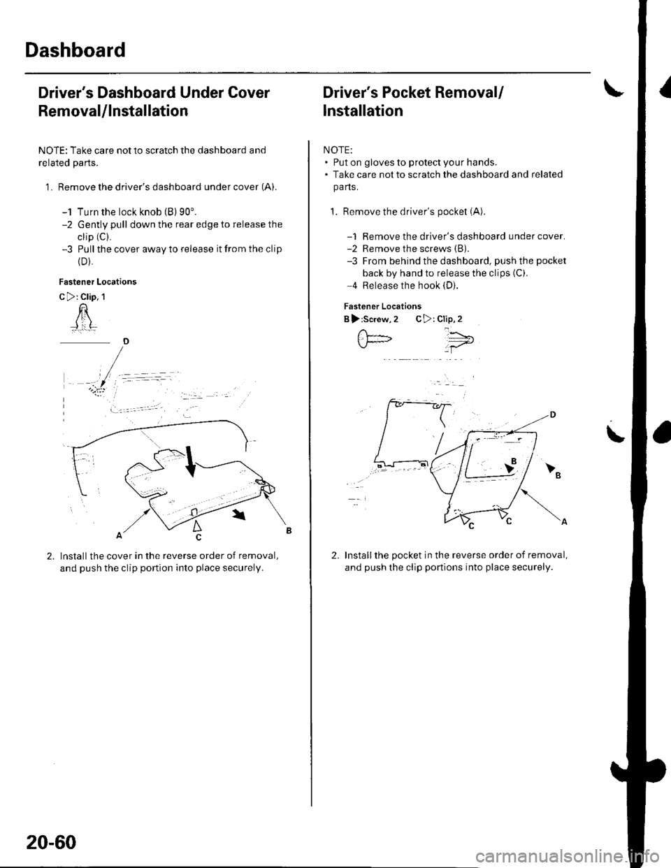
Driver's Dashboard Under Cover
Removal/lnstallation
NOTE: Take care not to scratch the dashboard and
related parts.
1 . Remove the driver's dashboard under cover (A).
-1 Turn the lock knob (B) 90'.-2 Gently pull down the rear edge to release the
clip (C).
-3 Pull the cover away to release it from the clip
{D).
Fastener Locations
C >: Clip. 1
n
Installthe cover in the reverse order of removal,
and push the clip portion into place securely.
)
20-60
Driver's Pocket Removal/
lnstallation
NOTE:. Put on gloves to protect your hands.. Take care not to scratch the dashboard and related
pa ns.
1. Remove the driver's pocket (A)
-1 Remove the driver's dashboard under cover.-2 Remove the screws (B).
-3 From behind the dashboard, push the pocket
back by hand to release the clips (C).
4 Release the hook (D).
Fastener Locations
B ):Screw,2 C>: Clip,2
Installthe pocket in the reverse order of removal,
and push the clip portions into place securely.
','"\5;;t='
\
2.