Head HONDA CIVIC 2003 7.G Owner's Manual
[x] Cancel search | Manufacturer: HONDA, Model Year: 2003, Model line: CIVIC, Model: HONDA CIVIC 2003 7.GPages: 1139, PDF Size: 28.19 MB
Page 104 of 1139
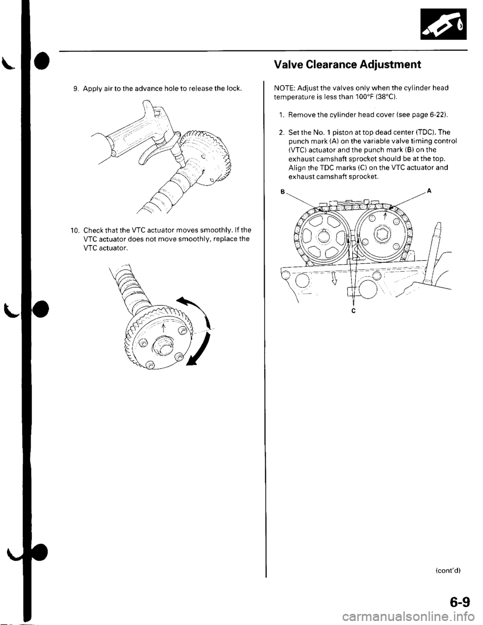
9. Apply air to the advance hole to release the lock.
Check that the VTC actuator moves smoothly. lf the
VTC actuator does not move smoothly, replace the
VTC acluator.
10.
Valve Glearance Adiustment
NOTE: Adjust the valves only when the cylinder head
temperature is less than 100'F (38'C).
1. Remove the cylinder head cover (see page 6-22).
2. Set the No. 1 piston at top dead center (TDC). The
punch mark (A) on the variable valve timing control
(VTC) actuator and the punch mark (B) on the
exhaust camshaft sprocket should be at the top.
Align the TDC marks (C) on the VTC actuator and
exhaust camshaft sprocket.
{cont'd)
6-9
Page 105 of 1139
Gylinder Head
IValve Clearance Adjustment (cont'd)
3. Select the correct thickness feeler gauge for the
valves you're going to check.
Intake: 0.21 0.25 mm (0.008-0.010 in.)
Exhaust; 0.28 0.32 mm (0.011 0.013 in.)
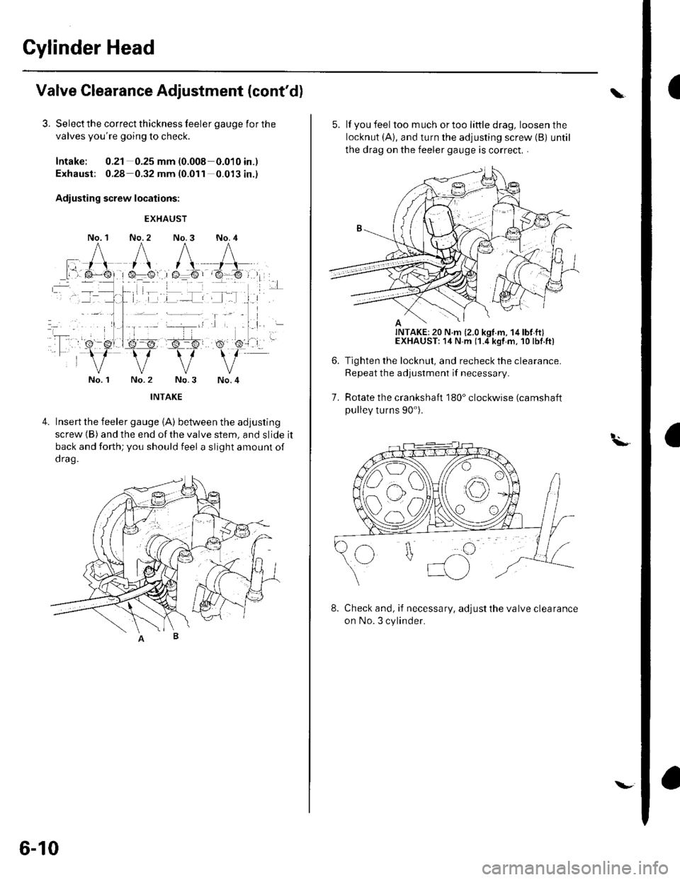
Adiusting screw locations:
No. 1
EXHAUST
No. 2 No.3 No. 4
No. 1No.4
4.Insert the feeler gauge {A) between the adjusting
screw (B) and the end ofthe valve stem, and slide it
back and forth; you should feel a slight amount of
d rag.
6-10
\.
5. lf you feel toomuchortoolittledrag, loosenthe
locknut (A), and turn the adjusting screw {B) until
the drag on the feeler gauge is correct. .
Tighten the locknut, and recheck the clearance.
Repeat the adjustment if necessary
Rotate the crankshaft 180" clockwise (camshaft
pulley turns 90').
7.
t.\-
8. Check and, if necessary, adjust the valve clearance
on No. 3 cylinder.
Page 106 of 1139
10.
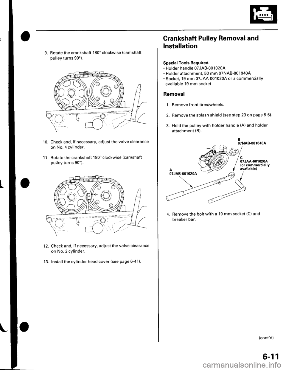
9. Rotate the crankshaft 180" clockwise (camshaft
pullev turns 90').
Check and, if necessary, adjust the valve clearance
on No.4 cylinder.
Rotate the crankshaft 180" clockwise (camshaft
pulley turns 90").
Check and, if necessary, adjust the valve clearance
on No. 2 cylinder.
Install the cylinder head cover (see page 6-41).
11.
12.
Crankshaft Pulley Removal and
Installation
Special Tools Required. Holder handle 07JAB-001020A. Holder attachment, 50 mm 07NAB-001040A. Socket, 19 mm 07JAA-001020,4 or a commercially
available 19 mm socket
Removal
1. Remove front tires/wheels.
2. Remove the splash shield (see step 23 on page 5-5).
3. Hold the pulley with holder handle (A) andholder
attachment (B).
B07NAB-001040A
el
/ Srroo.oo,oroo/ (or commercially
f available)
/
Remove the bolt with a 19 mm socket (C) and
breaker bar.
(cont'd)
6-11
Page 107 of 1139
Cylinder Head
Crankshaft Pulley Removal and
Installation (cont'dl
Installation
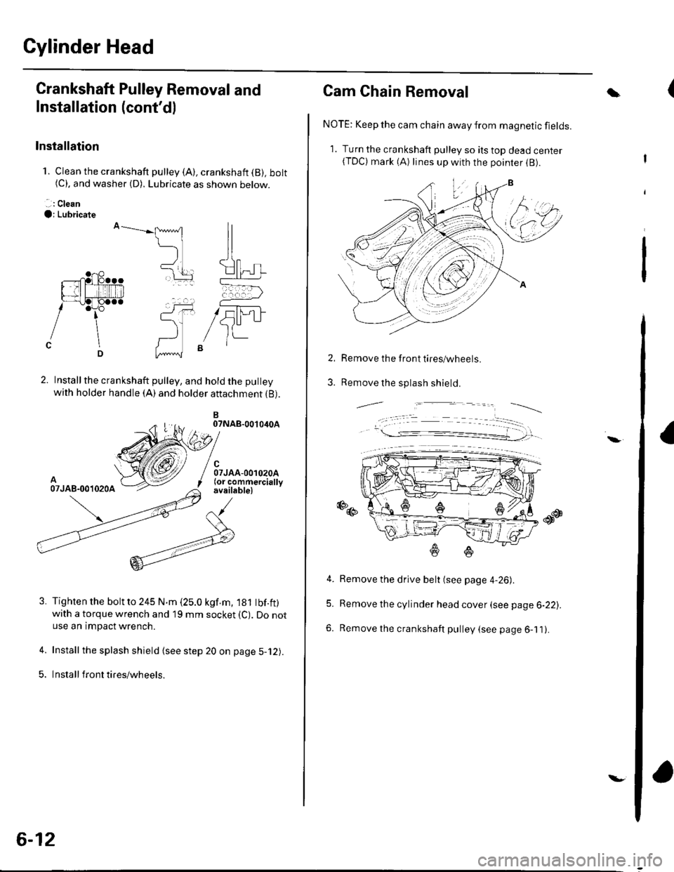
1. Clean the crankshaft pulley (A), crankshaft (B), bolt(C). and washer (D). Lubricate as shown below.
. .: Clean
O; Lubricate
Installthe crankshaft pulley, and hold the pulley
with holder handle (A) and holder attachment {B).
B07NAB-0010iroA
A07JAB-001020A
Tighten the bolt to 245 N.m (25.0 kgf.m, 181 tbf.ft)with a torque wrench and 19 mm socket (C). Do notuse an impact wrench.
Install the splash shield (see step 20 on page 5-12).
Insta ll front tires/wh eels.
ll
ll
t[] rL-'....-----=a
(-, ,
5U-1JItt-
5.
6-12
\-
Cam Chain Removal
NOTE: Keep the cam chain away from magnetic fields.
1. Turn the crankshaft pulley so ils top dead center(TDC) mark (A) lines up with the poinrer (B).
Remove the front tires/wheels.
Remove the splash shield.
a
2.
3.
-,,--.=.-----__--_
4. Remove the drive belt (see page 4-26).
5. Remove the cylinder head cover (see page 6-22).
6. Remove the crankshaft pulley (see page 6-11).
\
Page 109 of 1139
Cylinder Head
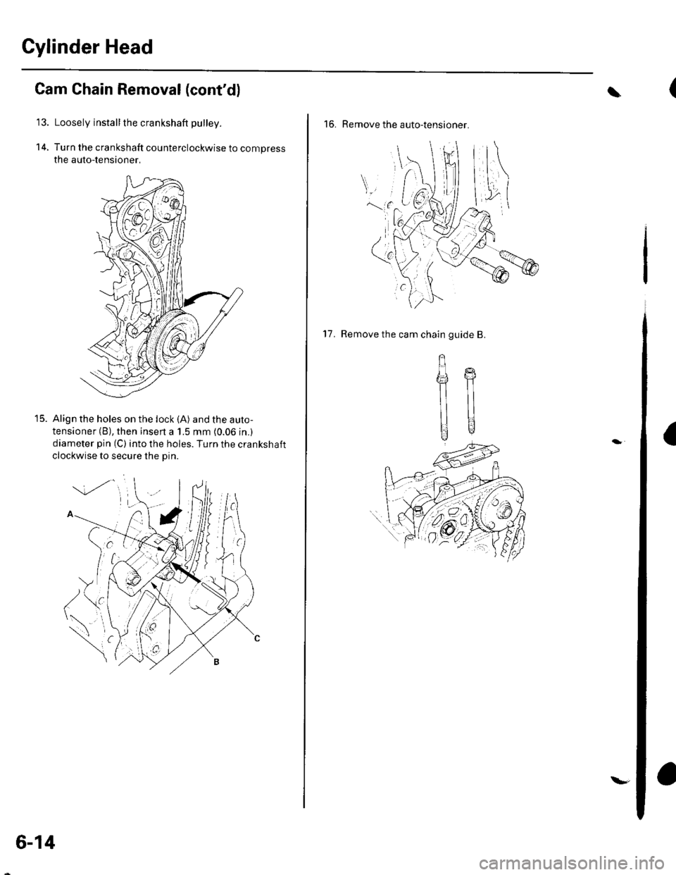
14.
Cam Chain Removal (cont'd)
Loosely install the crankshaft pulley.
Turn the crankshaft counterclockwise to compress
the auto-lensioner,
Align the holes on the lock (A) and the auto-
tensioner (B), then insen a 1.5 mm (0.06 in.)
diameter pin (C) into the holes. Turn the crankshaft
clockwise to secure the Din.
t5.
6-14
\-
(\
16. Remove the auto-tensioner.
a
17. Remove the cam chain guide B.
gffi
llll
UU
Page 111 of 1139
Gylinder Head
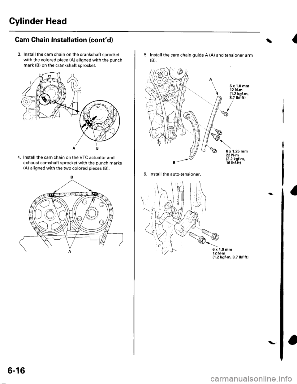
Cam Chain Installation (cont'dl
3. Installthe cam chain on the crankshaft sprocket
with the colored piece (A) aligned with the punch
mark (B) on the crankshaft sprocket.
Installthe cam chain on the VTC actuator and
exhaust camshaft sprocket with the punch marks(A) aligned with the two colored pieces (B).
B
6-16
{\
5. Installthe cam chain guide A (A) and tensioner arm(B).
6x1.0mm12 N.m{1,2 kgf.m,8.7 tbf.ftt
I'6
8 x 1.25 mm22 N.m12.2kgt.m,16 tbf.ft)
6. Install the auto-tensi
6x1,0mm12Nm(1.2 kgt.m, 8.7 lbf ti)
a
a
Page 113 of 1139
Gylinder Head
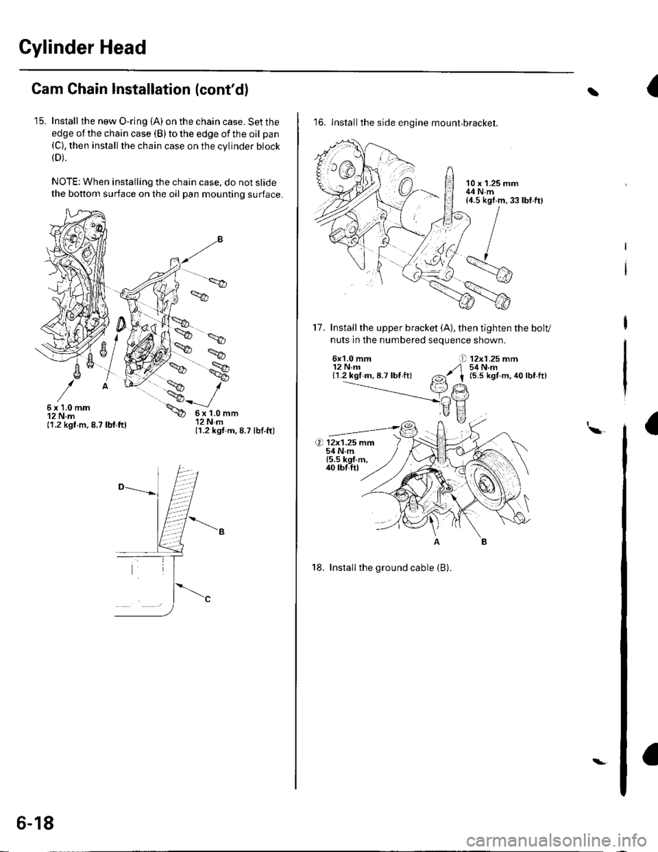
Cam Chain Installation (cont'd)
'15. Install the new O-ring (A) on the chain case. Set the
edge of the chain case (B) to the edge of the oil pan(C), then install the chain case on the cvlinder block(D).
NOTE: When installing the chain case, do not slide
the bottom surface on the oil pan mounting surface.
',.9
6x1.0mm12 N.m(1.2 kgt.m.8.7 lbf.ft)
6x1.0mm12Nm(1.2 kgf.m,8.7 lbf.ft)
6-18
\-
{t
16. lnstallthe side engine mount.bracket.
17. Installthe upper bracket (A), then tighten the bolv
nuts in the numbered seouence shown.
6x1.0 mm12 N.m{1.2 kgl m, 8.7 lbf ft}
12x1.25 mm54 N.m(5.5 kgt m, 40 lbf.ft)
I\a
18. Install the ground cable (B).
rbf.ft)
Page 114 of 1139
19.
20.
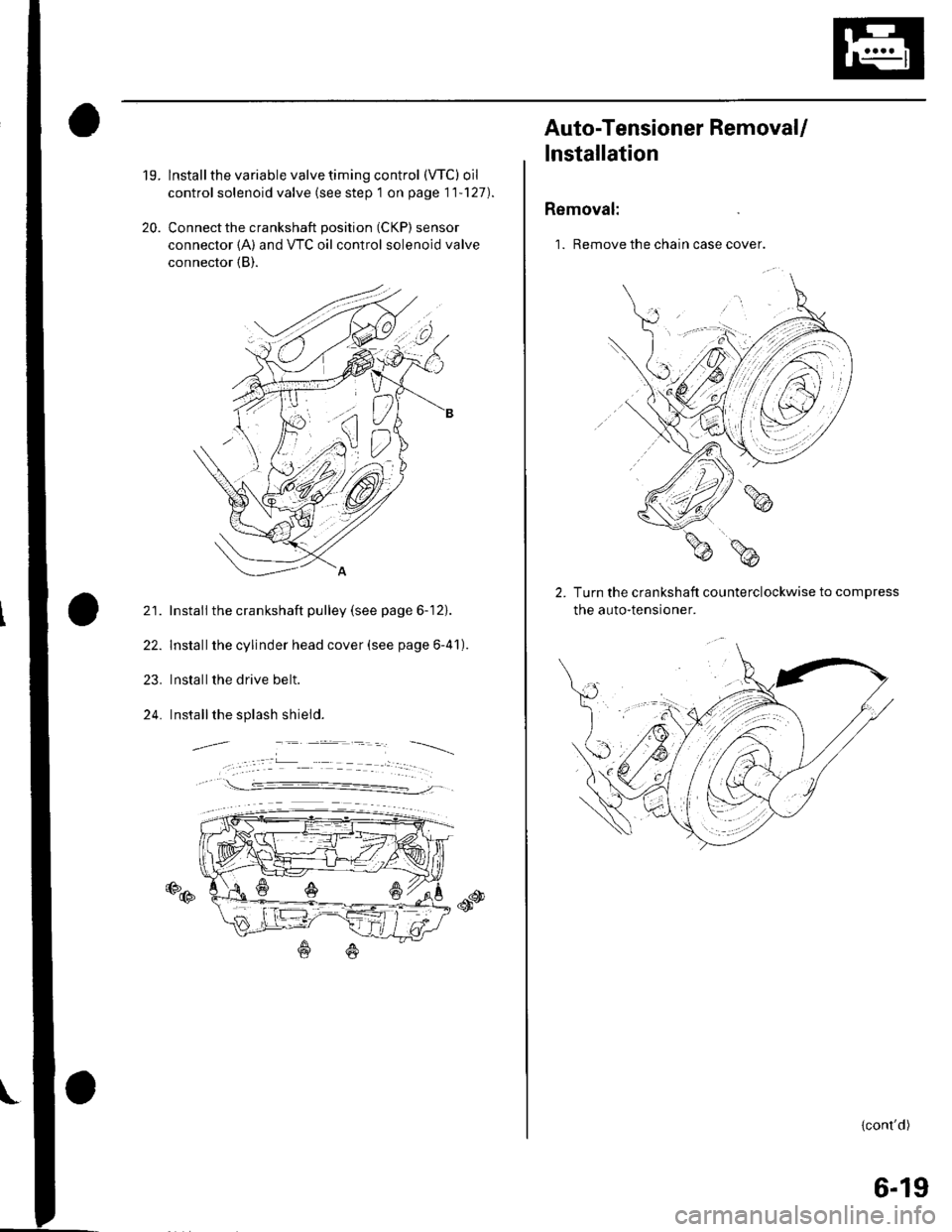
lnstall the variable valve timing control (VTC) oil
control solenoid valve (see step 1 on page 11'127).
Connect the crankshaft position (CKP) sensor
connector {A) and VTC oil control solenoid valve
connector (B).
21. Install the crankshaft pulley (see page 6-12).
22. Installthe cylinder head cover (see page 6-41).
23. Installthe drive belt.
24. Installthe splash shield.
€D@
Auto-Tensioner RemovaU
lnstallation
Removal:
1. Remove the chain case cover.
Turn the crankshaft counterclockwise to compress
the auto-tensroner.
{cont'd)
6-19
Page 115 of 1139
Gylinder Head
Auto-Tensioner Removal/l nstallation
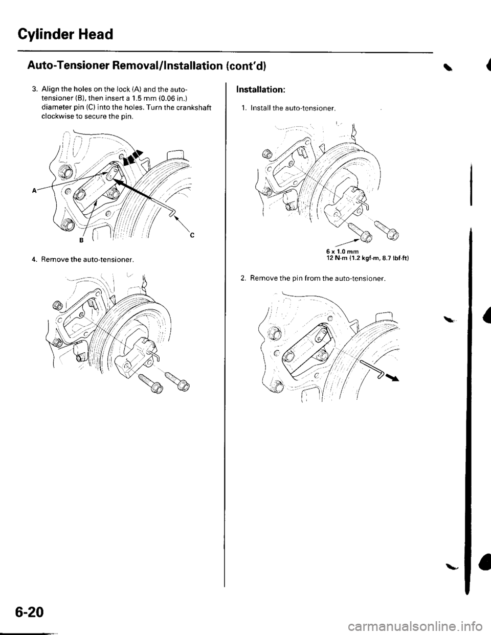
3. Align the holes on the lock (A) and the auto-
tensioner (B), then insert a 1.5 mm (0.06 in.)
diameter pin (C) into the holes. Turn the crankshaft
clockwise to secure the oin.
4. Remove the auto-tensioner.
6-20
\-
(cont'dl
Installation:
1. Install the auto-tensioner.
\
6x1.0mm12 N.m {1.2 kgt.m, 8.7 lbt.tt)
Remove the pin from the auto-tensioner.
a\
Page 117 of 1139
Gylinder Head
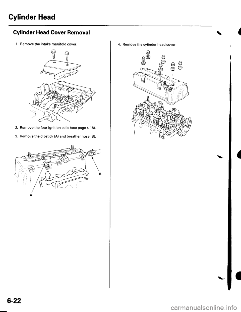
Cylinder Head Cover Removal
1. Remove the intake manifold cover.
2. Remove the four ignition coils (see page 4-'18).
3. Remove the dipstick (A) and breather hose (B).
6-22
\-
\
4, Remove the cylinder head cover
V:t :;t 1
|
,'.i/
(
(