k2 terminal HONDA CIVIC 2003 7.G Owner's Manual
[x] Cancel search | Manufacturer: HONDA, Model Year: 2003, Model line: CIVIC, Model: HONDA CIVIC 2003 7.GPages: 1139, PDF Size: 28.19 MB
Page 95 of 1139
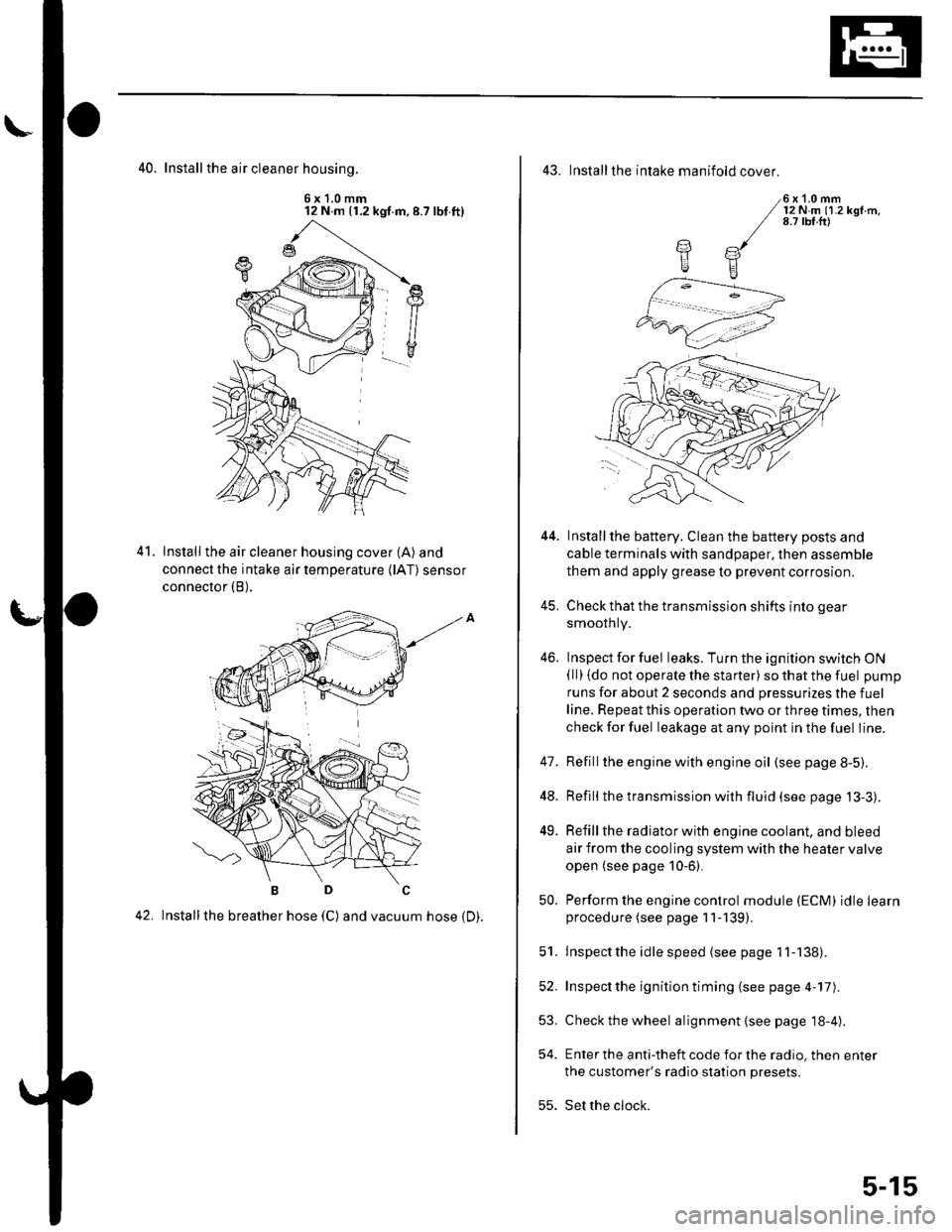
40. Install the air cleaner housinq.
6x1.0mm12 N m (1.2 kgf.m,8.7 lbt.ft)
Install the air cleaner housing cover (A) and
connect the intake air temperature (lAT) sensor
connector (B),
42. Installthe breather hose (C) and vacuum hose 1D).
41.
43. Installthe intake manifold cover.
6x1.0mm12Nm11.2kgf.m.8.7 tbf.ft)
Installthe battery. Clean the battery posts and
cable terminals with sandpaper, then assemble
them and apply grease to prevent corrosion.
Check that the transmission shifts into gear
smoothly.
Inspect for fuel leaks. Turn the ignition switch ON(ll) {do not operate the starter) so that the fuel pump
runs for about 2 seconds and pressurizes the fuel
line. Repeat this operation two or three times, then
check for fuel leakage at any point in the fuel line.
Refillthe engine with engine oil (see page 8-5).
Refill the transmission with fluid (see page 13-3).
Refill the radiator with engine coolant, and bleed
air from the cooling system with the heater valve
open (see page 10-6).
Perform the engine control module (ECM) idle learnprocedure (see page 11-139).
Inspect the idle speed (see page 1 1-138).
Inspect the ignition timing (see page 4-17).
Check the wheel alignment {see page 18-4).
Enter the anti-theft code for the radio, then enter
the customer's radio station presets.
Set the clock.
YE
44.
41.
]tE
46.
48.
49.
52.
53.
54.
50.
51.
55.
5-15
Page 136 of 1139
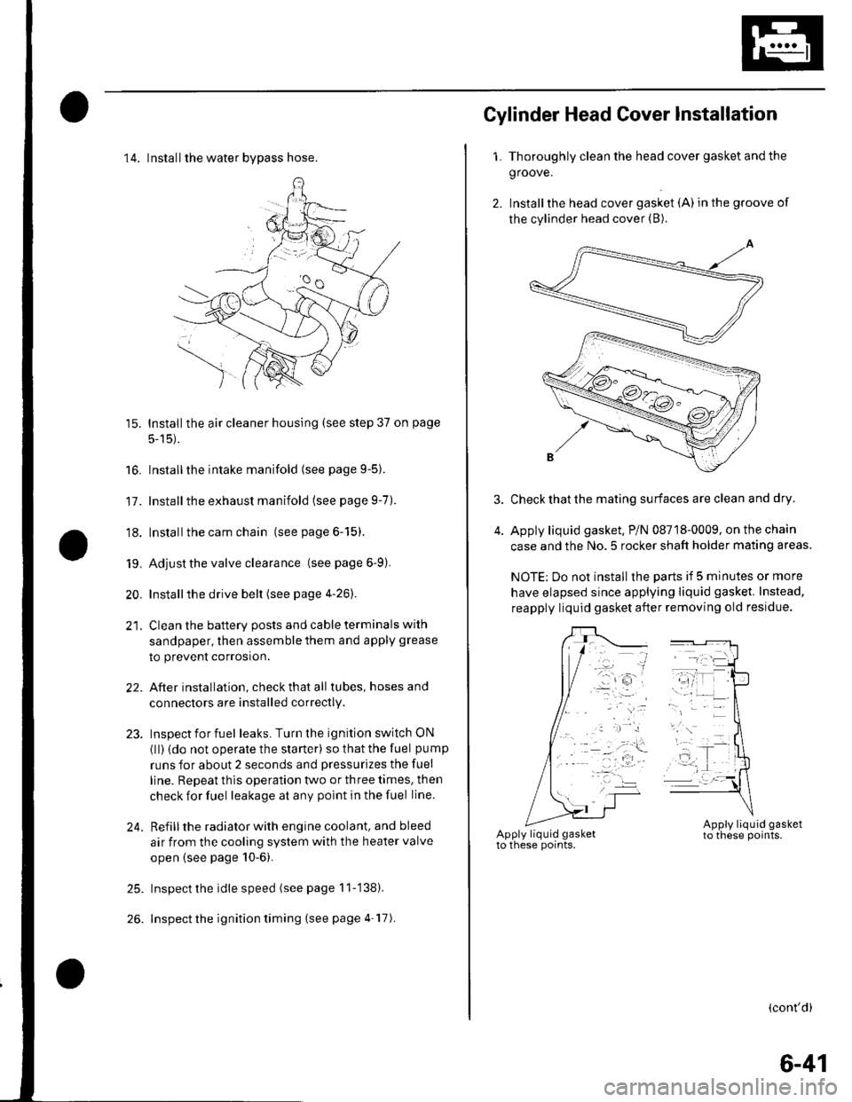
14. Installthe water bvpass hose.
15. Installthe air cleaner housing (see step 37 on page
5-15).
16. Installthe intake manifold (see page 9-5).
17. Installthe exhaust manifold (see page 9-7).
'18. Installthe cam chain (see page 6-15).
19. Adjust the valve clearance (seepage6-9).
20. Installthe drive belt (see page 4-26).
21. Clean the battery posts and cable terminals with
sandpaper, then assemble them and apply grease
to prevent corrosion.
22. After installation, checkthatall tubes, hosesand
connectors are installed correctly.
23. Inspectforfuel leaks. Turn the ignition switch ON
{ll) {do not operate the starter) so that the fuel pump
runs for about 2 seconds and pressurizes the fuel
line. Repeat thls operation two or three times, then
check for fuel leakage at any point in the fuel line.
24. Refillthe radiator with engine coolant, and bleed
air from the cooling system with the heater valve
open (see page 10-6).
25. Inspect the idle speed (see page 11-'138).
26. Inspect the ignition timing (see page 4-17).
Gylinder Head Cover lnstallation
1. Thoroughly clean the head cover gasket and the
groove.
2. Installthe head cover gasket (A) in the groove of
the cylinder head cover (B).
Check that the mating surfaces are clean and dry.
Apply liquid gasket. P/N 08718-0009, on the chain
case and the No.5 rocker shaft holder mating areas.
NOTE: Do not install the parts if 5 minutes or more
have elapsed since applying liquid gasket. Instead,
reapply liquid gasket after removing old residue.
(cont'd)
6-41
Page 170 of 1139
Engine Lubrication
Oil Pressure Switch Test
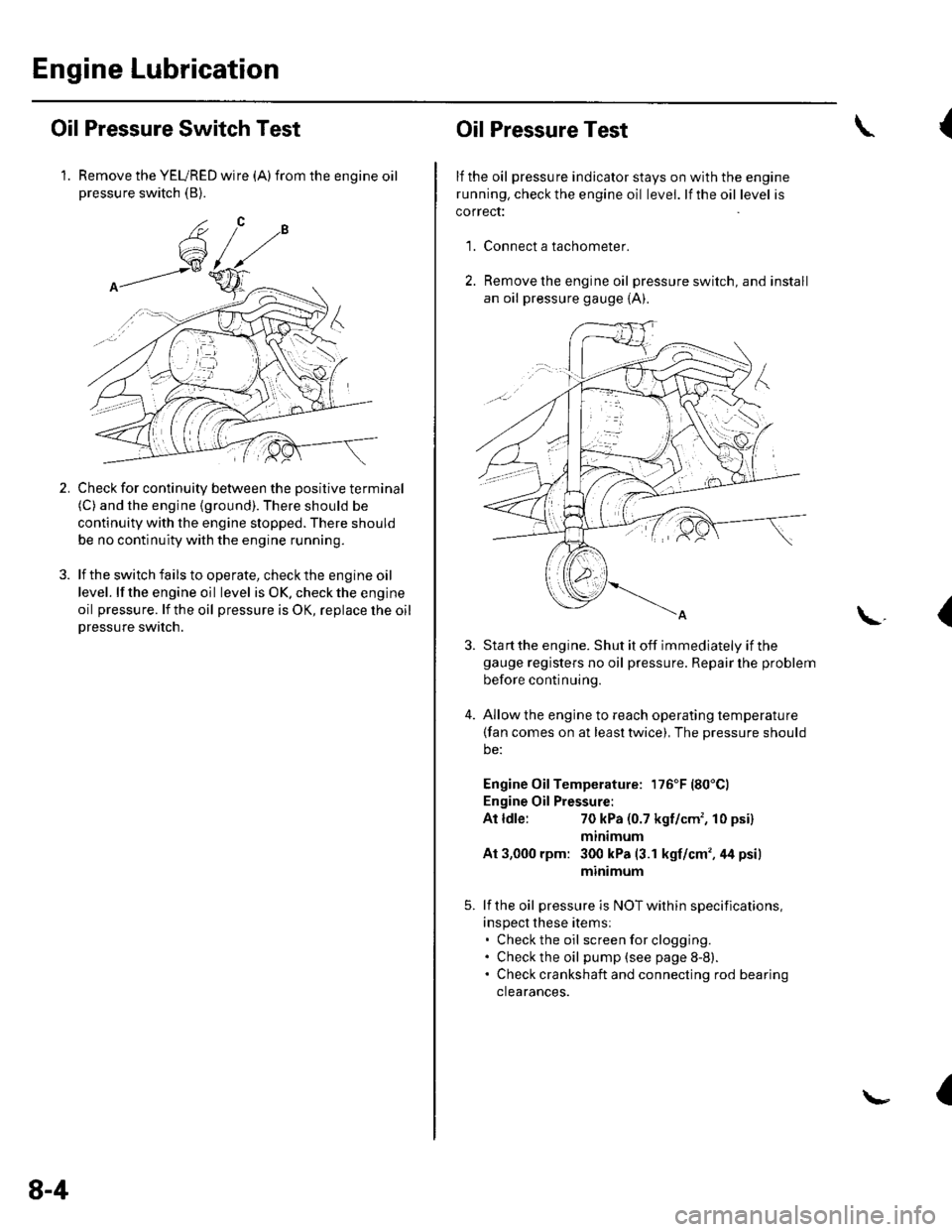
1. Remove the YEURED wire (A)from the engine oilpressure switch (B).
Check for continuity between the positive terminal(C) and the engine (ground). There should be
continuity with the engine stopped. There should
be no continuity with the engine running.
lf the switch fails to operate, check the engine oil
level. lf the engine oil level is OK. check the engine
oil pressure. lf the oil pressure is OK, replace lhe oil
Dressure switch.
2.
8-4
Oil Pressure Test
lf the oil pressure indicator stays on with the engine
running. check the engine oil level. lf the oil level is
correct:
Connect a tachometer.
Remove the engine oil pressure switch, and install
an oil pressure gauge {A).
{
'1.
\.(
4.
Sta rt the engine. Shut it off immediately if thegauge registers no oil pressure. Repair lhe problem
before continuing.
Allow the engine to reach operating temperature(fan comes on at least twice), The pressure should
be:
Engine Oil Temperature: 176'F (80'Cl
Engine Oil Pressure:
At ldle:70 kPa (0.7 kgf/cm', 10 psi)
mtntmum
At 3,000 rpm: 300 kPa (3.1 kgf/cm',44 psi)
minimum
lf the oil pressure is NOT within specifications,
inspect these items:. Check the oil screenforclogging.. Check the oil pump (see page 8-8).. Check crankshaft and connecting rod bearing
clearances.
I
Page 194 of 1139
Cooling System
Fan Motor Test
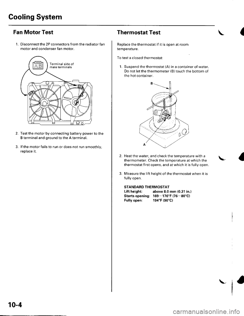
1. Disconnect the 2P connectors from the radiator fan
motor and condenser fan motor.
Test the motor by connecting battery power to the
B terminal and ground to the A terminal.
lf the motor fails to run or does not run smoothly,
reptace rL
10-4
\
Thermostat Test
Replace the thermostat if it is open at room
remperalure.
To test a closed thermostatl
1. Suspend the thermostat (A) in a container of water.
Do not let the thermometer {B) touch the bottom of
the hot container.
(\
2.
3.
Heat the water, and check the temDerature with a
thermometer. Check the temperature at which the
thermostat first opens, and at which it is fully open.
Measure the lift height of the thermostat when it is
fullv ooen.
STANDARD THERMOSTAT
Lift height; above 8.0 mm (0.31 in.)
Starts opening: 169 176"F(76 80"C)
Fully open: 194"F {90'Cl
\.
Page 204 of 1139
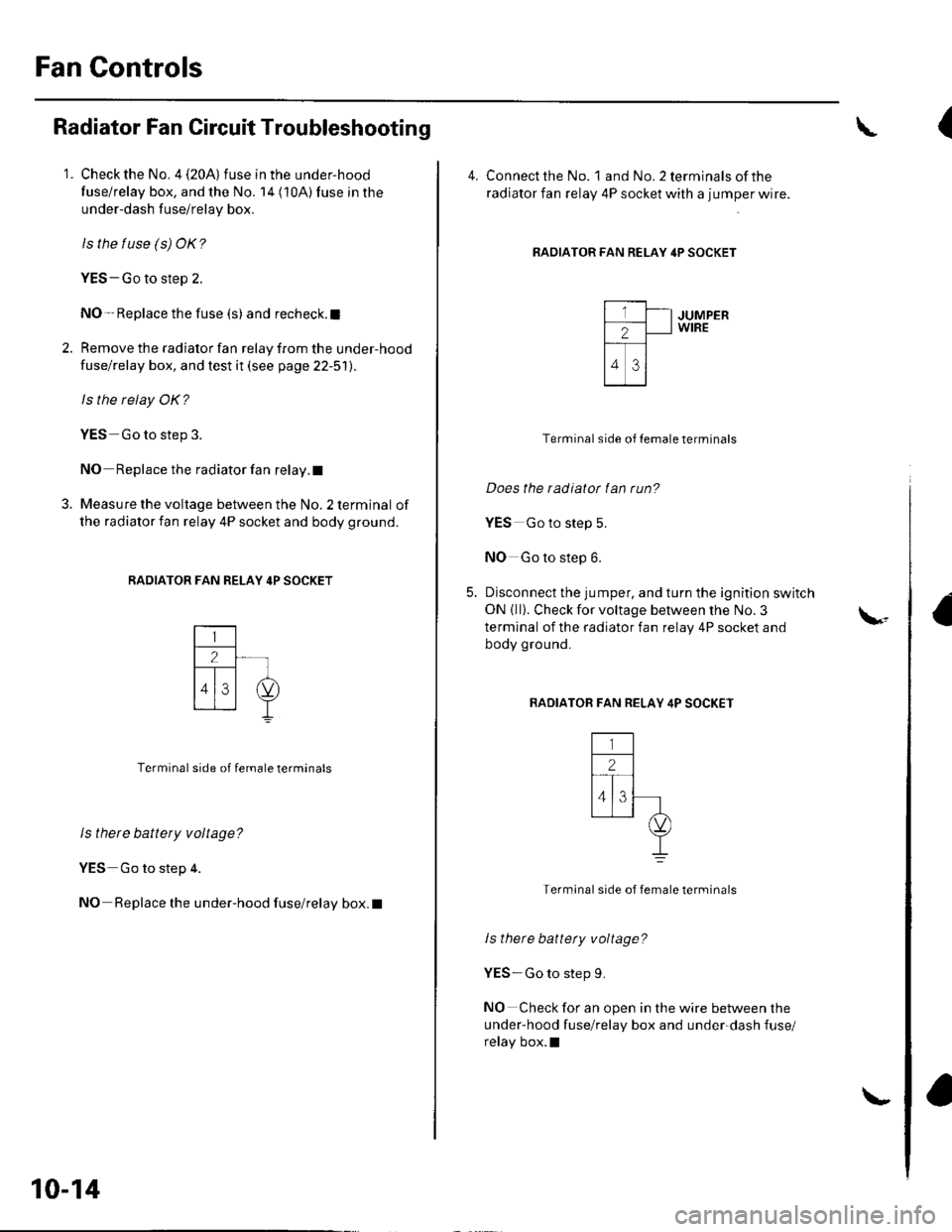
Fan Gontrols
Radiator Fan Circuit Troubleshooting
1. Check the No. 4 (20A) fuse in the under-hood
fuse/relay box, and the No. 14 (10A) fuse in the
under-dash fuse/relay box.
ls the tuse (s) OK?
YES-Go to step 2.
NO- Replace the fuse (s) and recheck.l
2. Remove the radiator fan relay from the under-hood
fuse/relay box, and test it (see page 22-51).
ls the relay OK?
YES Go to step 3.
NO Replace the radiator fan relay. t
3. Measure the voltage between the No. 2 terminal of
the radiator fan relay 4P socket and body ground.
RADIATOR FAN RELAY 4P SOCKET
Terminal side of female terminals
ls there battery voltage?
YES Go to step 4.
NO Replace the under-hood fuse/relay box. I
10-14
\-
(
4. Connect the No. landNo.2terminalsofthe
radiator fan relay 4P socket with a jumper wire.
RADIATOR FAN RELAY 4P SOCKET
JUMPERWIRE
Terminal side of Iemale terminals
Does the radiatot fan run?
YES Go to step 5.
NO Go to step 6.
Disconnect the jumper, and turn the ignition switch
ON { ll}. Check for voltage between the No. 3
terminal of the radiator fan relay 4P socket and
body ground.
BADIATOB FAN RELAY 4P SOCKET
Termlnal side of female terminals
ls there battety voltage?
YES-Go to step 9.
NO Check for an open in the wire between the
under-hood fuse/relay box and under-dash fuse/
relay box.l
\-
Page 205 of 1139
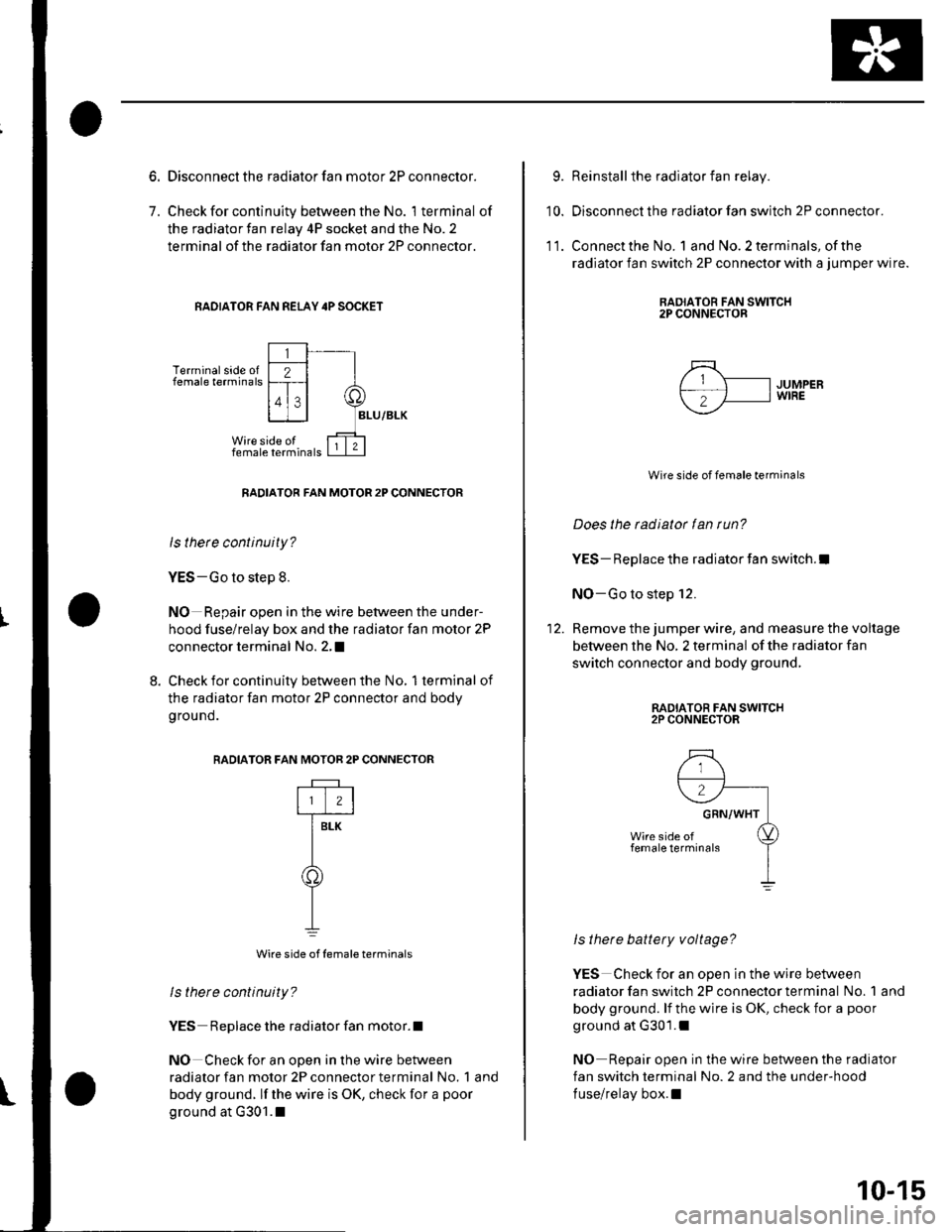
7.
Disconnect the radiator fan motor 2P connector.
Check for continuity between the No. 1 terminal of
the radiator fan relay 4P socket and the No. 2
terminal of the radiator fan motor 2P connector.
RAOIATOR FAN REI-AY 4P SOCKET
Terminal side offemale terminals
RADIATOR FAN MOTOR 2P CONNECTOR
ls thete continuity?
YES-Go to step 8.
NO Repair open in the wire between the under-
hood fuse/relay box and the radiator fan motor 2P
connector terminal No. 2,I
8. Check for continuity between the No, 1terminal of
the radiator fan motor 2P connector and bodv
g rou nd.
RADIATOR F
Wire side of female terminals
ls there continuity?
YES Replace the radiator fan motor.l
NO Check for an open in the wire between
radiator fan motor 2P connector terminal No. 1 and
body ground. lf the wire is OK, check for a poor
ground at G301.1
AN MOTOR 2P CONNECTOR
rftr
T-
Y
9.
10.
Reinstall the radiator fan relay.
Disconnect the radiator fan switch 2P connector.
Connect the No. 1 and No. 2 terminals, of the
radiator fan switch 2P connector with a jumper wire.
RAOIATOR FAN SWITCH2P CONNECTOR
11.
5\- IJUMPERf-; 'fl I wrRE
--
Wire side of female terminals
Does the radiator fan run?
YES- Replace the radiator fan switch.l
NO-Go to step 12.
Remove the jumper wire, and measure the voltage
between the No, 2 terminal of the radiator fan
switch connector and body ground,
RADIATOR FAN SWITCH2P CONNECTOR
ls there battery voltage?
YES Check for an open in the wire between
radiator fan switch 2P connector terminal No. 1 and
body ground. lf the wire is OK, check for a poor
ground at G301.1
NO Repair open in the wire between the radiator
fan switch terminal No. 2 and the under-hood
fuse/relay box.l
10-15
Page 206 of 1139
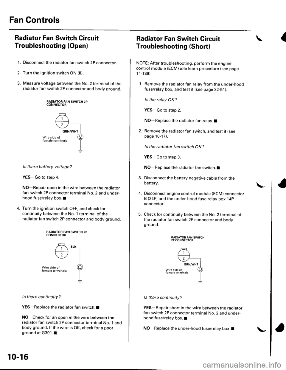
Fan Controls
Radiator Fan Switch Circuit
Troubleshooting (Openl
1. Disconnect the radiator fan switch 2P connector.
2. Turn the ignition switch ON (ll).
3. Measure voltage between the No.2 terminal ofthe
radiator fan switch 2P connector and body ground.
RADIATOR FAN SWITCH 2PCONNECTOR
ls there battety voltage?
YES-Go to step 4.
NO- Repair open in the wire between the radiator
fan switch 2P connector terminal No. 2 and under-
hood fuse/relay box.l
Turn the ignition switch OFF, and check for
continuity between the No. '1 terminal of the
radiator fan switch 2P connector and body ground.
RADIATOB FAN SWITCX 2PCONNECTOR
ls there continuity?
YES Replace the radiator fan switch. t
NO Check for an open in the wire between theradiator fan switch 2P connector terminal No. 1 and
body ground. lf the wire is OK, check for a poor
ground at G301.1
10-16
\-
Radiator Fan Switch Circuit
Troubleshooting (Short)
NOTE: After troubleshooting, perform the engine
control module (ECM)idle learn procedure (see page
1 1,139).
1. Remove the radiator fan relay from the under-hood
fuse/relay box, and test it (see page 22-51).
ls the relay OK?
YES Go to step 2.
NO Replace the radiator fan relay.I
2. Remove the radiator fan switch, and test it (see
page 10-17 ).
Is the radiatot tan switch OK?
4.
YES Go to step 3.
NO Replace the radiator fan switch.I
Disconnect the battery negative cable from the
battery.
Disconnect engine control module {ECM) connector
B (24P) and the under hood fuse relay box 14P
connector.
Check for continuity between the No. 2 terminal of
the radiator fan switch 2P connector and bodygrouno.
RADIATOR FAN SWITCH2P CONNECTOR
lstnere continuity?
YES Repair short in the wire between the radiator
fan switch 2P connector terminal No. 2 and under-
hood fuse/relay box.l
NO Replace the under-hood fuse/relay box.t
\I
\
Page 207 of 1139
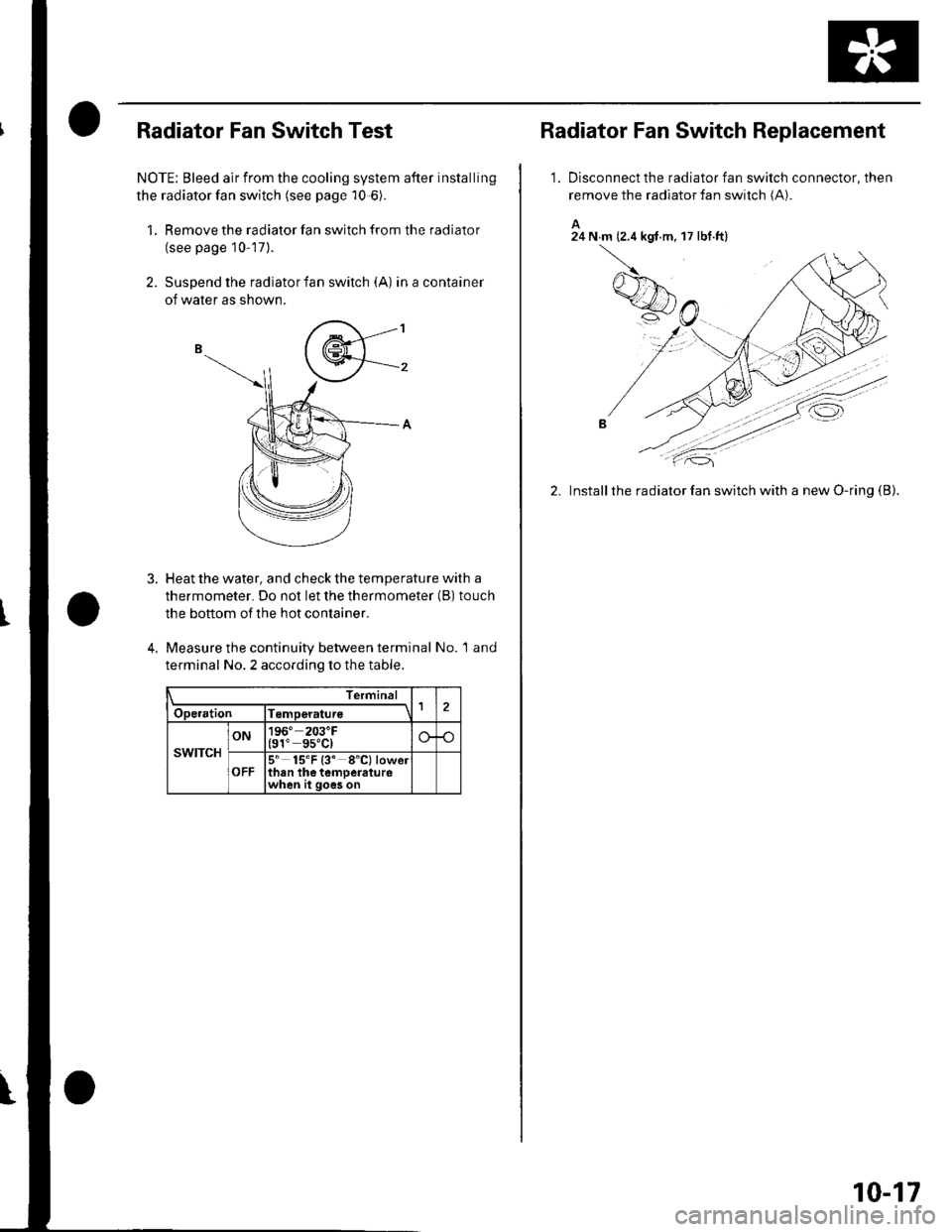
Radiator Fan Switch Test
NOTE: Bleed air from the cooling system after installing
the radiator fan switch (see page 10-6).
1, Remove the radiator fan switch from the radiator
(see page 10-17).
2. Suspend the radiator fan switch (A) inacontainer
of water as shown.
3. Heat the water, and check the temperature with a
thermometer. Do not let the thermometer (B) touch
the bottom of the hot conlainer.
4. Measure the continuity between terminal No. 1 and
terminal No. 2 according to the table.
Termina
Operation lTemperature1
swtTcH
ON196" 203'F(91" gs"C)
OFF5' 15'F {3' 8'C) lowelthan the temoeraturewhen it goes on
Radiator Fan Switch Replacement
1.Disconnect the radiator fan switch connector, then
remove the radiator fan switch (A).
A24 N m (2.4 kgt.m, 17 lbt.ftl
2. Installthe radiator fan switch with a new O-ring (B).
10-17
Page 210 of 1139
General Troubleshooting Information
Intermittent Failures
The term "intermittent failure" means a svstem mav
have had a failure. but it checks OK now. lf the
Malfunction Indicator Lamp (MlL) on the dash does not
come on, check for Door connections or loose terminals
at all connectors related to the circuit that Vou are
troubleshooting.
Opens and Shorts
"Ooen" and "Short" are common electrical terms. An
open is a break in a wire or at a connection. A short is
an accidental connection of a wire to ground or to
another wire. In simple electronics, this usually means
something won't work at all. With complex electronics(such as ECMs)this can sometimes mean something
works, but not the way it's supposed to.
How to Use the PGM Tester or a Scan Tool
lf the MIL {Malfunction Indicator Lamp} has come on
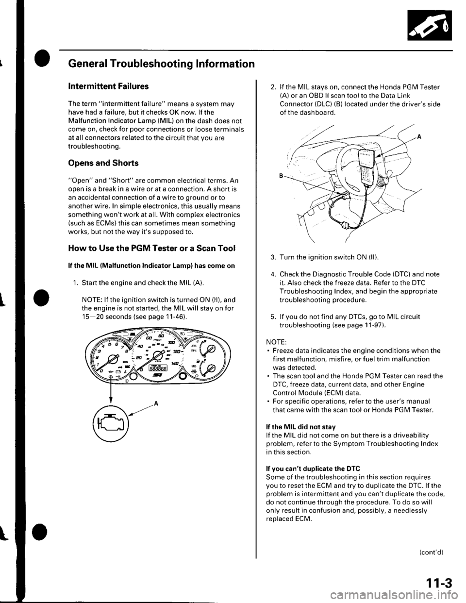
'1. Start the engine and check the MIL {A).
NOTE: lf the ignition switch is turned ON (ll), and
the engine is not started, the MIL will stay on for
15 20 seconds (see page 11-46).
K-> ;"PN/.- -::: - -d V-: !
w:ix&K#
2. lf the MIL stays on, connect the Honda PGM Tester(A) or an OBD ll scan tool to the Data Link
Connector {DLC) (B) located under the driver's side
of the dashboard.
3.
5.
Turn the ignition switch ON (ll).
Check the Diagnostic Trouble Code (DTC) and note
it. Also check the freeze data. Refer to the DTC
Troubleshooting Index, and begin the appropriate
troubleshooting procedure.
lf you do not find any DTCS, go to MIL circuit
troubleshooting (see page 11-97).
NOTE:. Freeze data indicates the engine conditions when the
first malfunction, misfire, or fuel trim malfunction
was detected.. The scan tool and the Honda PGM Tester can read the
DTC, freeze data, current data, and other Engine
Control l\4odule {EClvl) data.. For specific operations, refer to the user's manual
that came with the scan tool or Honda PG l\4 Tester.
lf the MIL did not stay
lf the MIL did not come on but there is a driveability
problem, refer to the Symptom Troubleshooting Index
in this section.
lf you can't duplicate the DTC
Some of the troubleshooting in this section requires
you to reset the ECM and try to duplicate the DTC. lf rhe
problem is intermittent and you can't duplicate the code,
do not continue through the procedure. To do so will
only result in confusion and, possibly, a needlessly
replaced ECM.
(cont'd)
11-3
Page 212 of 1139
How to Troubleshoot Circuits at the ECM
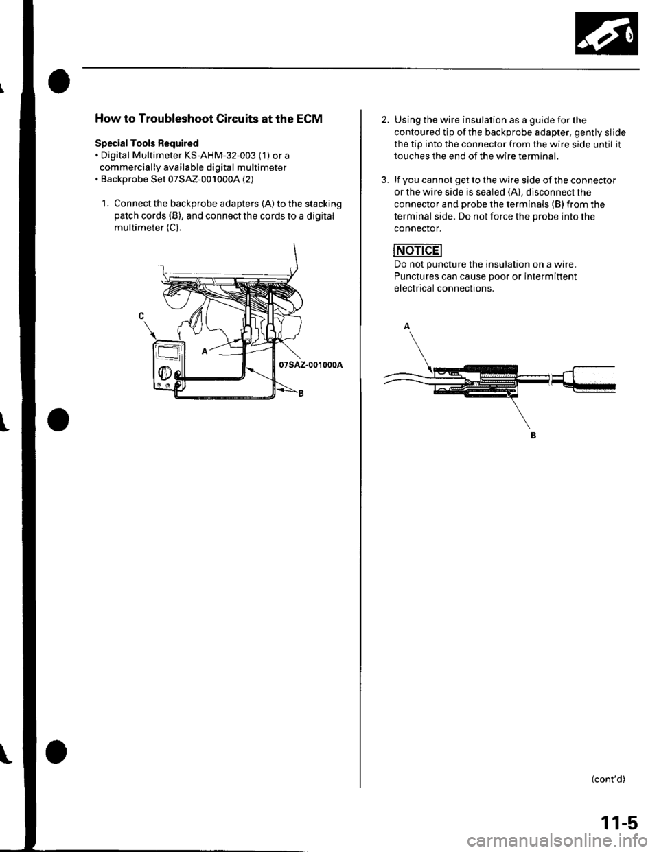
Special Tools Required. Digital Multimeter KS-AHM-32-003 (1) or a
commercially available digital multimeter. Backprobe Set 07SAZ-0010004 (2)
1. Connect the backprobe adapters (A) to the stacking
patch cords (B), and connect the cords to a digital
multimeter (C).
07sAz-001000A
2. Using the wire insulation as a guide for the
contoured tip ofthe backprobe adapter, gently slide
the tip into the connector from the wire side until it
touches the end of the wire terminal.
3. lf you cannot get to the wire side of the connector
or the wire side is sealed (A), disconnect the
connector and probe the terminals (B) from the
terminal side. Do not force the Drobe into the
connector.
Do not puncture the insulation on a wire.
Punctures can cause Door or intermittent
electrical connections.
(cont'd)
11-5