wheel torque HONDA CIVIC 2003 7.G Owner's Manual
[x] Cancel search | Manufacturer: HONDA, Model Year: 2003, Model line: CIVIC, Model: HONDA CIVIC 2003 7.GPages: 1139, PDF Size: 28.19 MB
Page 591 of 1139

3.
Trailing Arm Removal/lnstallation
1.Raise the rear of the vehicle, and suppon it with
safety stands in the proper location (see page 1,8).
Remove the rear wheels.
Remove the knuckle (see page 18-28).
Place the floor jack under the trailing arm (A) to
support it.
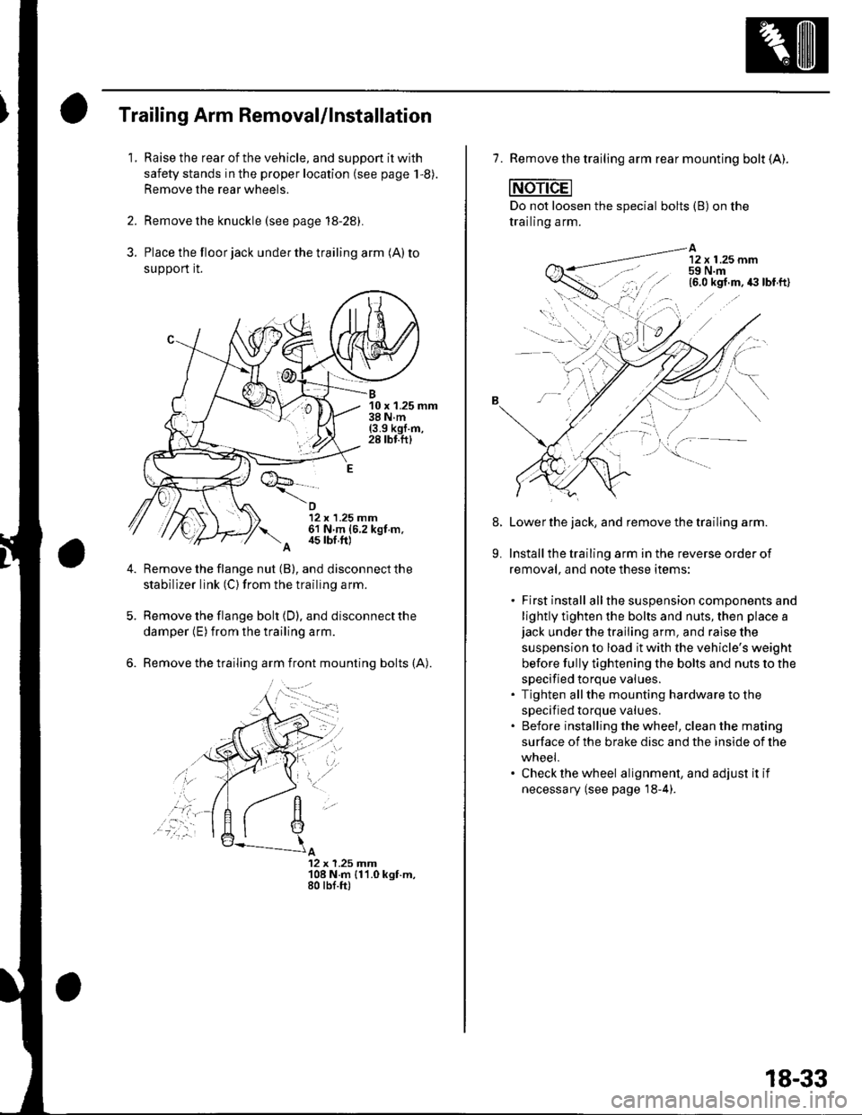
B10 x 1.25 mm38Nm(3.9 kgl.m,28 tbf.ftl
12 x 1.25 mm61 N m (6.2 kgt m.
A 4s tbf,ft)
Remove the flange nut (B), and disconnect the
stabilizer link (C) from the trailing arm.
Remove the flange bolt {D), and disconnect the
damper (E) from the trailing arm.
Remove the trailing arm front mounting bolts (A).
A12 x 1.25 Jnm108 N.m {11.0 kgt.m,80 tbf.ft)
,'a':r -
7. Remove the trailing arm rear mounting bolt (A).
Do not loosen the special bolts (B) on the
trailing arm.
A12 x 1.25 mm59 N.m
-----\':,'.ttg
'.,--1..-r.':1
Lower the jack, and remove the trailing arm.
Install the trailing arm in the reverse order of
removal, and note these items:
. First install allthe suspension components and
lightly tlghten the bolts and nuts, then place ajack under the trailing arm, and raise the
suspension to load it with the vehicle's weight
before fully tightening the bolts and nuts to the
specified torque values.. Tighten allthe mounting hardware to the
specif ied torque values.. Before installing the wheel, clean the mating
surface of the brake disc and the inside of the
wneei.. Check the wheel alignment, and adjust it if
necessary (see page'18-4).
8.
9.
18-33
Page 595 of 1139

D
Installation
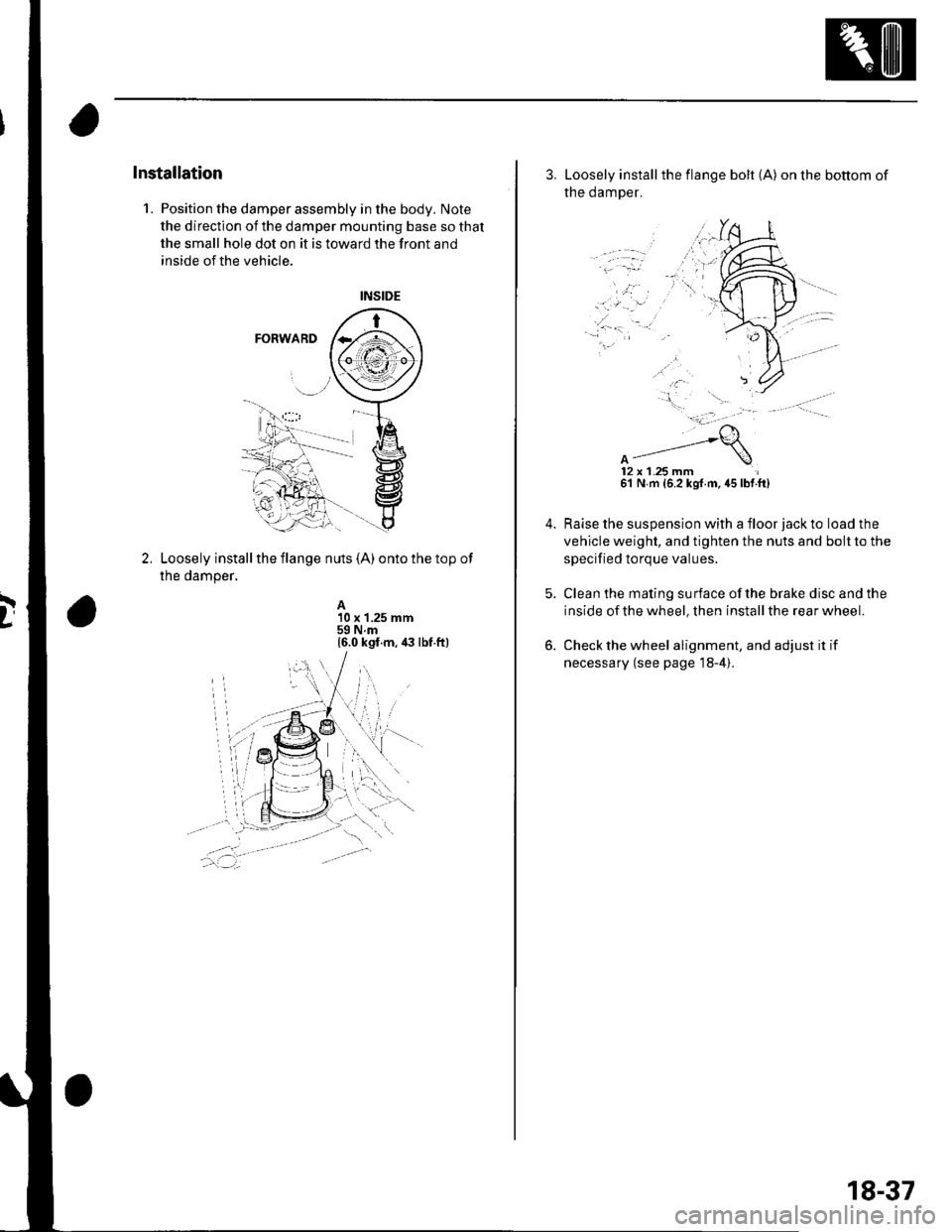
1. Position the damper assembly in the body. Note
the direction of the damper mounting base so that
the small hole dot on it is toward the front and
inside of the vehicle.
Loosely install the flange nuts (A) onto the top of
the damper,
A10 x 1.25 mm59 N.m16.0 kgt.m, ia lbt ft)
3. Loosely installthe flange bolt (A) on the bottom of
the damper.
12x 1.25 mm61 N m {6.2 kgf.m. 45 lbf.ft)
Raise the suspension with a floor jack to load the
vehicle weight, and tighten the nuts and bolt to the
specified torque values.
Clean the mating surface ofthe brake disc and the
inside of the wheel, then install the rear wheel.
Check the wheel alignment, and adjust it if
necessary (see page 18-4).
18-37
Page 608 of 1139

Front Brake Disc lnspection
Runout
1. Raise the front of the vehicle, and support it with
safety stands in the proper location (see page 1-8).
Remove the front wheels.
2. Remove the brake pads (see page 19-11).
3. Inspect the disc surface for damage and cracks.
Clean the disc thoroughly, and remove all rust
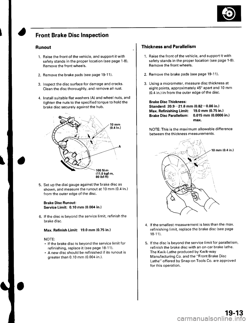
4. lnstall suita ble flat washers (A) andwheel nuts,and
tighten the nuts to the specified torque to hold the
brake disc securely against the hub.
Set up the dial gauge against the brake disc as
shown, and measure the runout at 10 mm (0 4 in.)
from the outer edge of the disc.
Brake Disc Runout:
Service Limit: 0.10 mm (0.00tt in.l
lf the disc is beyond the service limit, refinish the
brake disc.
Max. Retinish Limit: 19.0 mm (0.75 in.)
NOTE:. lf the brakedisc is beyondtheservice limitfor
refinishing, replace it (see page 18-1 1).
. A new disc should be refinished if its runout is
greater than 0.10 mm (0.004 in.).
Thickness and Parallelism
1. Raise the front of the vehicle, and support it with
safety stands in the proper location (see page 1-8).
Remove the front wheels.
2. Remove the brake pads (see page 19-11).
3. Using a micrometer, measure disc thickness at
eight points, approximately 45" apart and 10 mm
{0.4 in.) in from the outer edge of the disc.
Brake Oisc Thickness:
Standard: 20.9 21.8 mm {0.82-0.86 in.}
Max. Refinishing Limit: 19.0 mm 10.75 in.)
Brake Disc Parallelism: 0.015 mm 10.0(X)6 in.)
max.
NOTE: This is the maximum allowable difference
between the thickness measurements
10 mm lo.it in.l
lf the smallest measurement is less than the max.
refinishing limit, replace the brake disc (see page
18-11).
lf the disc is beyond the service limit for parallelism,
refinish the brake disc with an on-car brake lathe.
The Kwik-Lathe produced by Kwik-way
Manufacturing Co. and the "Front Brake Disc
Lathe" offered by Snap-on Tools Co. are approved
for this operation.
4.
': . --'t-'"'-
t,.
19-13
Page 617 of 1139

Conventional Brake Components
Rear Brake Disc Inspection
Runout
1. Raise the rear of the vehicle, and support it with
safety stands in the proper location (see page 1-8).Remove the rear wheels,
2. Remove the brake pads (see page 19-20).
3. Inspect the disc surface for damage and cracks.
Clean the disc thoroughly, and remove all rust,
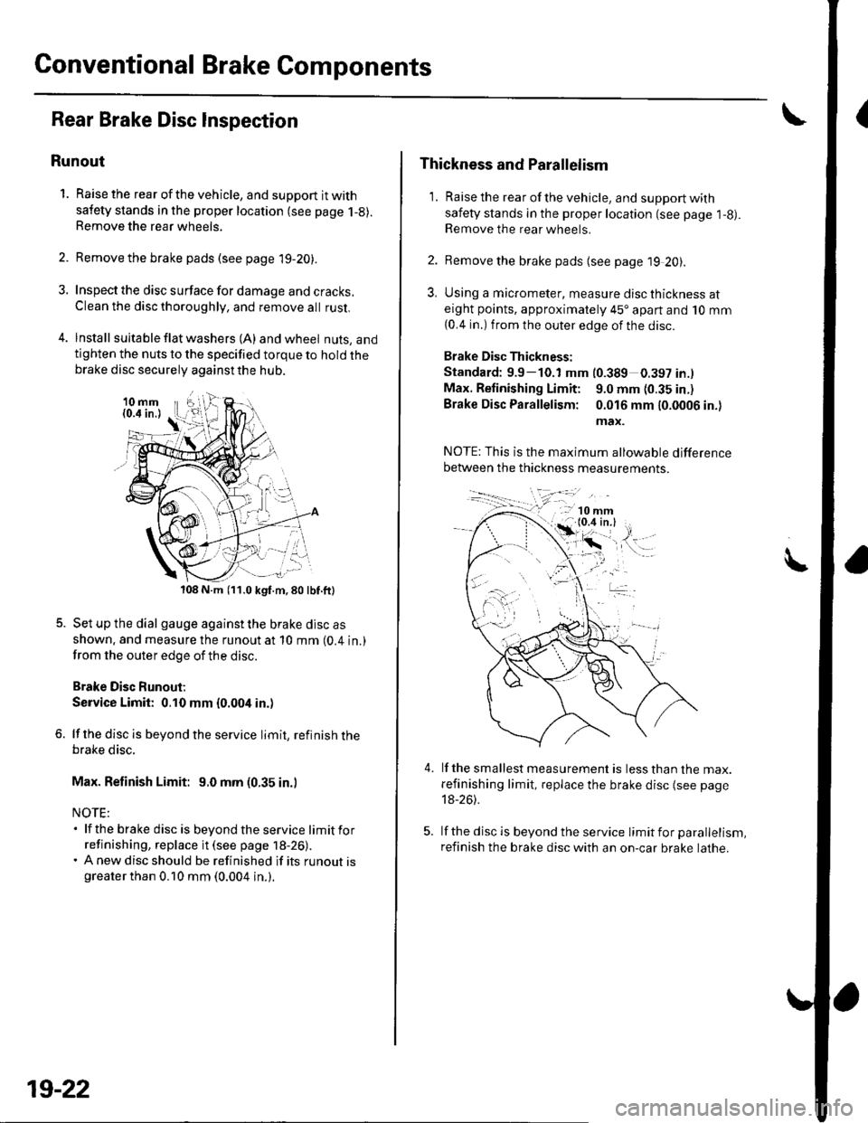
4. lnstall suita ble f lat washers (A) and wheel nuts, andtighten the nuts to the specified torque to hold thebrake disc securely against the hub.
108 N.m (11.0 kgf.m,80lbf.ft)
Set up the dial gauge against the brake disc as
shown. and measure the runout at 10 mm (0.4 in.)
from the outer edge of the disc.
Brake Disc Runout;
Service Limit: 0.10 mm {0.004 in.)
lf the disc is beyond the service limit, refinish thebrake disc.
Max. Refinish Limit: 9.0 mm (0.35 in.)
NOTE:. lf the brake disc is beyondtheservice limitfor
refinishing, replace it (see page 18-26).. A new disc should be refinished if its runout isgreater than 0.10 mm (0.004 in.).
19-22
Thickness and Parallelism
1. Raise the rear of the vehicle, and support with
safety stands in the proper location (see page l-g).Remove the rear wheels.
2. Remove the brake pads {see page 19 20).
3, Using a micrometer, measure disc thickness ateight points, approximately 45'apart and 10 mm
{0.4 in.) from the outer edge of the disc.
Brake Disc Thickness:
Standard: 9.9-10.1 mm (0.389 0.397 in.l
Max. Retinishing Limit: 9.0 mm (0.35 in.)
Brake Disc Parallelism: 0.016 mm 10.0006 in.)
max.
4.lf the smallest measurement is less than the max.
refinishing limit, replace the brake disc (see page
18-26).
lf the disc is beyond the service limit for parallelism,
refinish the brake disc with an on-car brake lathe.