Remove dashboard HONDA CIVIC 2003 7.G Owner's Guide
[x] Cancel search | Manufacturer: HONDA, Model Year: 2003, Model line: CIVIC, Model: HONDA CIVIC 2003 7.GPages: 1139, PDF Size: 28.19 MB
Page 971 of 1139
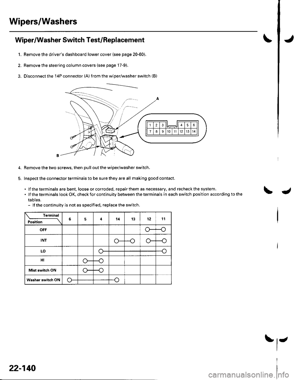
Wipers/Washers
1.
Wiper/Washer Switch Test/Replacement
Remove the driver's dashboard lower cover {see page 20-60).
Remove the steering column covers (see page 17-9).
Disconnecl the 14P connector (A) from the wiper/washer switch {B)
Remove the two screws, then pull out the wiper/washer switch.
Inspect the connector terminals to be sure they are all making good contact.
. lf the terminals are bent, loose or corroded, repairthem as necessary, and recheck the system..lftheterminalslookOK,checkforcontinuitybetweentheterminalsineachswitchpositlonaccordingtothe
tables,- lf the continuity is not as speciiied, replace the switch.
Terminal
Position6414l21211
OFFo--{
tNlo-
LOo-
HI
Mist switch ONr
Washor 3witch ON
22-140
J
Page 972 of 1139
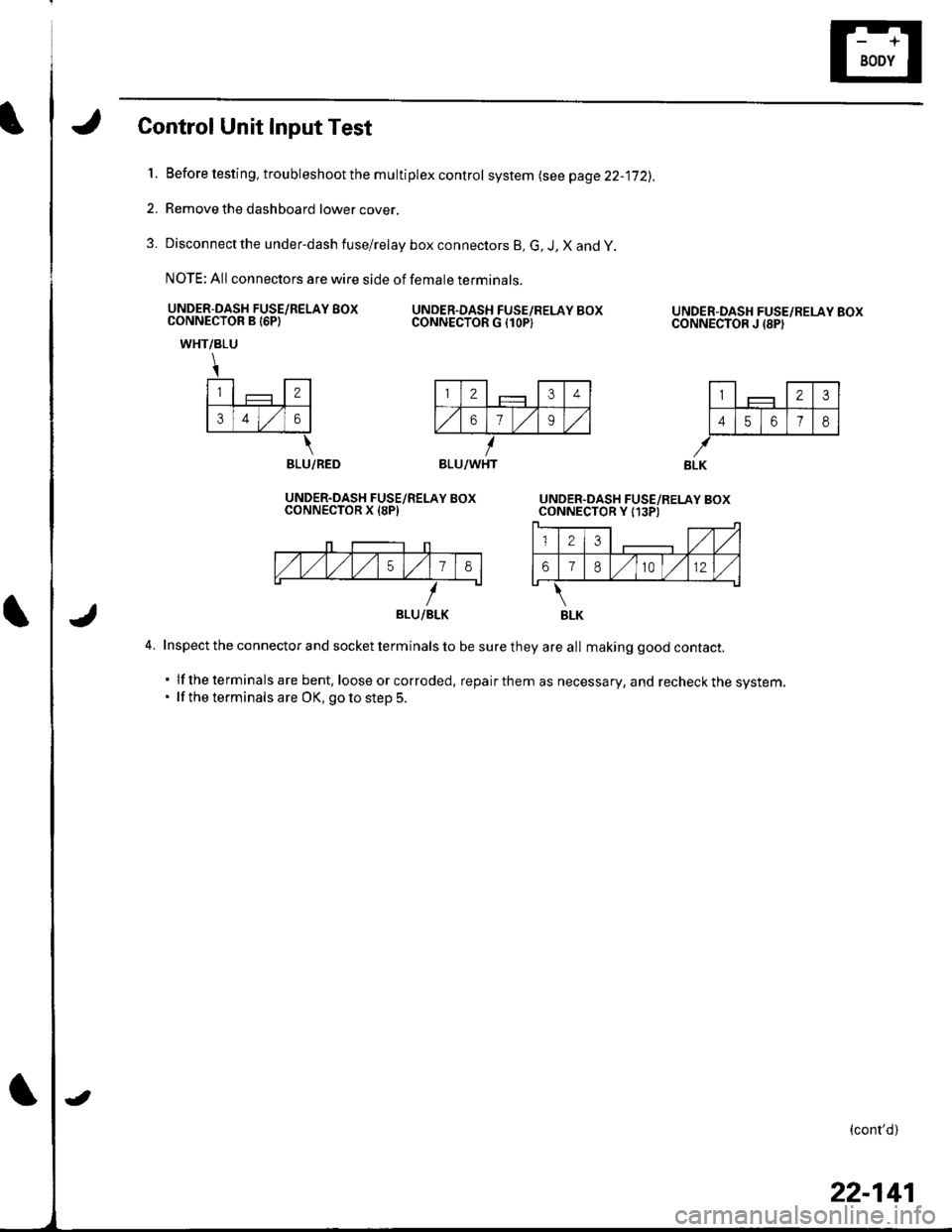
Control Unit Input Test
l.Before testing, troubleshoot the multiplex control system lsee page 22-jj2).
Remove the dashboard lower cover,
Disconnect the under-dash fuse/relay box connectors B, G, J, X and y
NOTE: All connectors are wire side of female terminals.
UNDER-DASH FUSE/RELAY BOXCONNECTOR B I6PIUNDER.DASH FUSE/RELAY BOXCONNECTOR G {1OP)
2.
3.
UNDER-DASH FUSE/RELAY BOXCONNECTOR J {8PI
l-,1 - llTtlF_j-JF-#
141516 7l8l
WHT/BLU
\
l-,1 - l-rl€ll
lslrlzlol
\BLU/RED
UNDER.DASH FUSE/RELAY BOXCONNECTOR X I8PI
4. Inspect the connector and socket terminals to be sure they are all making good contact.
. lf the terminals are bent, loose or corroded, repairthem as necessary, and recheckthe system.. lf the terminals are OK, goto step 5.
(cont'd)
BLU/WHT
BLU/BLK
22-141
Page 984 of 1139
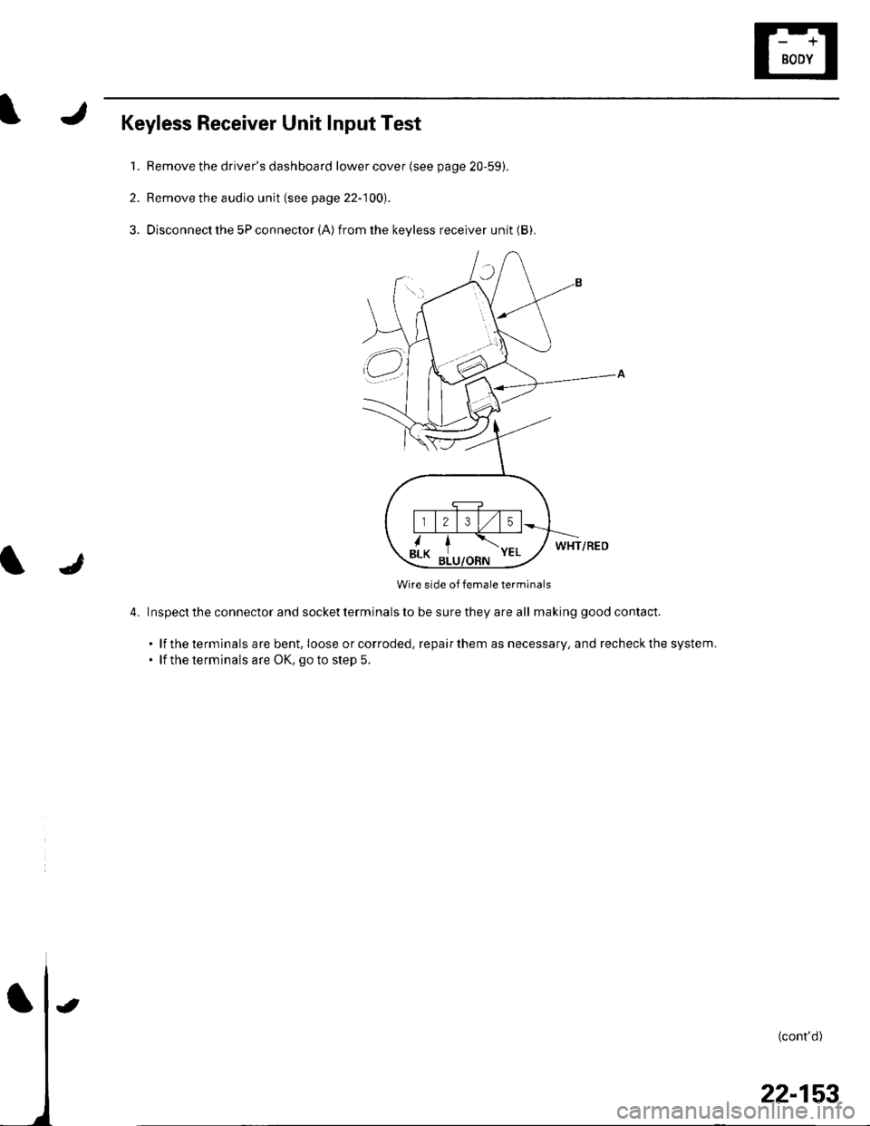
Keyless Receiver Unit Input Test
1. Remove the driver's dashboard lower cover (see page 20-59).
2. Remove the audio unit (see page 22-100).
3. Disconnect the 5P connector (A)from the keyless receiver unit (B).
WHT/RED
Wire side of female terminals
4. Inspecttheconnectorandsocketterminalstobesuretheyareall ma king good contact.
. lf the terminals are bent. Ioose orcorroded, repairthem as necessary, and recheckthe system.. lf the terminals are OK, go to step 5.
l
(cont'd)
t
22-153
Page 986 of 1139
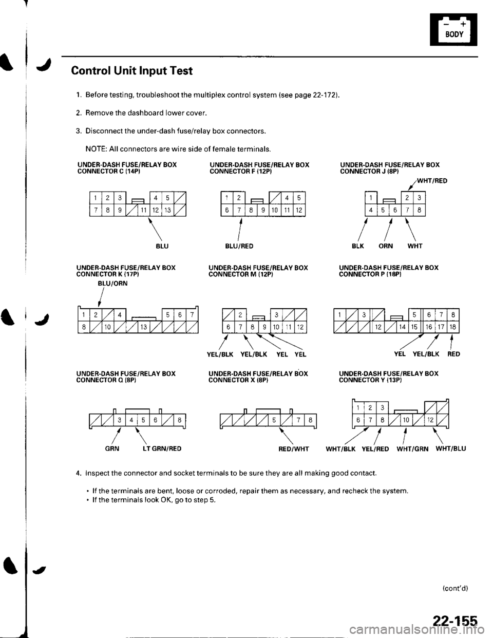
Control Unit Input Test
1. Before testing, trou bleshoot the m u ltiplex contro I system (see page 22-172).
2, Remove the dashboard lower cover.
3. Disconnect the under-dash fuse/relay box connectors.
NOTE: All connectors are wire side of female terminals.
UNDER.DASH FUSE/RELAY BOXCONNECTOR C {1itPlUNDER.DASH FUSE/RELAY BOXCONNECTOR F I12P)
UNDER.DASH FUSE/RELAY BOXCONNECTOR M Il2PI
UNDER-OASH FUSE/RELAY BOXCONNECTOR J {8PI
UNDER.OASH FUSE/RELAY BOXCONNECTOR P I18PIUNDER.DASH FUSE/RELAY BOXCONNECTOR K {17PI
BLU/ORN
UNDER.DASH FUSE/RELAY BOXCONNECTOR O (8P)
YEL/BLK YEL/BLK YEL YEL
UNDER-DAsH FUsE/neLeY sbxCONNECTOR X (8P)
YEL YEL/BLK
UNDER.DASH FUSE/RELAY BOXCONNECTOR Y {13P)
,/1,/34568
LT GRN/REDWHT/BLK YEL/RED WHT/GRN WHT/BLU
4. Inspect the connector and socket terminals to be sure they are all making good contact.
. lf the terminals are bent, loose orcorroded, repairthem as necessary, and recheckthe system.. lf the terminals look OK, go to step 5.
(cont'd)
GRN
BLU/REDBLU
RED/WHT
22-155
Page 996 of 1139
)
I
Troubleshooting
Before troubleshooting the immobilizer system,
troubleshoot any EClvl Diagnostic Trouble Codes (DTCS)
(see page 11-3), and make sure the ECM has no
malfunction.
Note these items before trou bleshooting:
. Due to the action of the immobilizer system, the
engine takes slightly more time to start than on a
vehicle without an immobilizer system.. When the system is normal, and the proper key is
inserted, the indicator light comes on for 2 seconds,
then it will go off.. If the indicatorstartsto blink after 2 seconds, or if the
engine does not start. remove any other immobilizer
keys or large key fobs on the key ring, then repeat the
starting procedure.
lf the engine still does not start, continue with thisprocedure.
1. Turn the ignition switch ON {ll) with proper key.
2. Check to see if the immobilizer indicator light
comes on.
Does the indicator light blink?
YES Disconnect the 7P connector from the
immobilizer control unit-receiver, then go to step 9.
NO Check for these problems, then go to step 3.
. Blown No. 9 (10A)fuse in the under-hood
fuse/relay box.I. An open in the wire between the gauge assembly
and the immobilizer control unit-receiver.l. A faulty immobilizer indicator light,I. An open in the wire between the gauge assembly
and the under-hood fuse/relay box.l
Remove the driver's dashboard lower cover (see
page 20-59).
Remove the steering column lower cover (see page
11-9).
l
-_--t
22-165
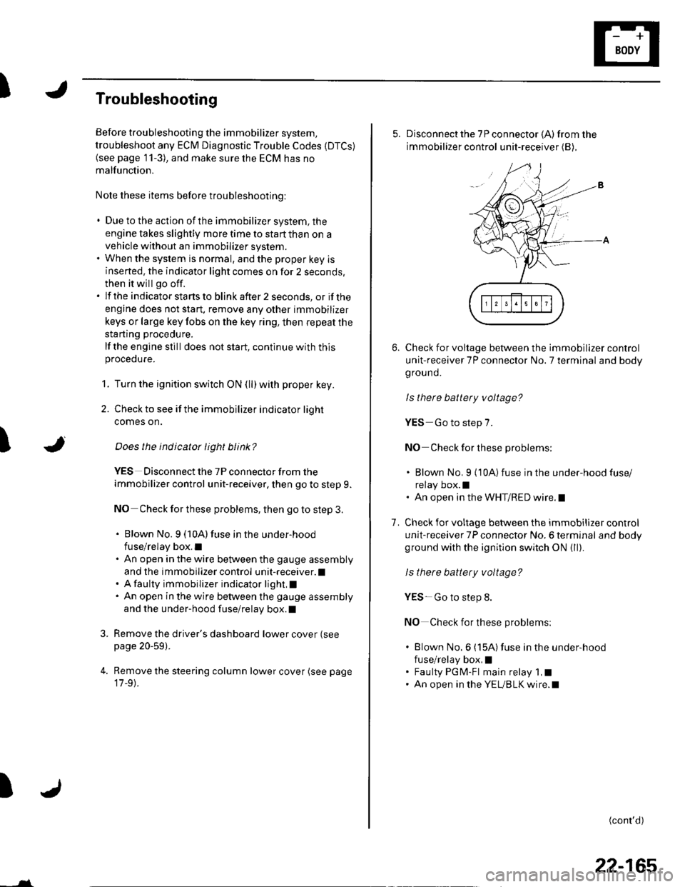
5. Disconnect the 7P connector (A)from the
immobilizer control unit-receiver (B),
Check for voltage between the immobilizer control
unit-receiver 7P connector No. 7 terminal and body
ground.
ls there battery voltage?
YES-Go to step 7.
NO Check for these problems;
. Blown No. 9 {10A)fuse in the under-hood fuse/
relay box.l. An open in the WHT/RED wire.l
Check for voltage between the immobilizer control
unit-receiver 7P connector No. 6 terminal and bodyground with the ignition switch ON {ll).
ls there battery voltage?
YES- Go to step 8.
NO Check for these problems:
. Blown No.6 (15A)fuse in the under-hood
fuse/relay box,I. Faulty PGM-Fl main relay 1,t. An open in the YEUBLK wire.l
1.
(cont'd)
Page 997 of 1139
lmmobilizer System
Troubleshooting (cont'dl
8. Check for voltage betvveen the immobilizer control
unit-receiver 7P connector No. 6 terminal and No. 1
rermlnat.
ls thete battery voltage?
YES Go to step 12.
NO Check for these problems,
. Open on the BRNI/EL wire.l. Faulty ECM.I
9. Remove the driver's dashboard lower cover (see
page 20-59).
10. Remove the steering column lower cover (see page
17-9).
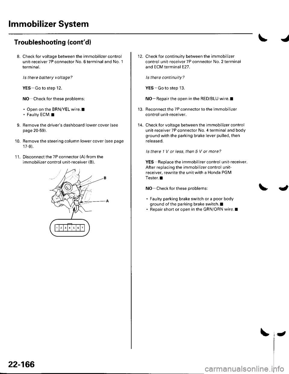
11. Disconnect the 7P connector (A) from the
immobilizer control unit-receiver (B).
22-166
-
Check for continuity between the immobilizer
control unit-receiver 7P connector No. 2 terminal
and ECM terminal E27.
ls there continuity?
YES-Go to step 13.
NO- Repair the open in the RED/BLU wire.I
Reconnect the 7P connector to the immobilizer
control unit-receiver.
Check for voltage between the immobilizer control
unit-receiver 7P connector No. 4 terminal and body
ground with the parking brake lever pulled, then
released.
ls there 1 V or less, then 5 V or more?
YES Replace the immobilizer control unit-receiver.
After replacing the immobillzer control unit-
receiver, rewrite the unit with a Honda PGM
Tester.l
NO Check for these problems:
. Faulty parking brake switch or a poor body
ground of the parking brake switch.l. Repair short or open in the GRN/ORN wire. I
13.
14.
{
Page 998 of 1139
t
2.
3.
lmmobilizer Control Unit-Receiver Replacement
'LRemove the driver's dashboard lower cover (see
page 20-59).
Remove the steering column covers (see page 17-
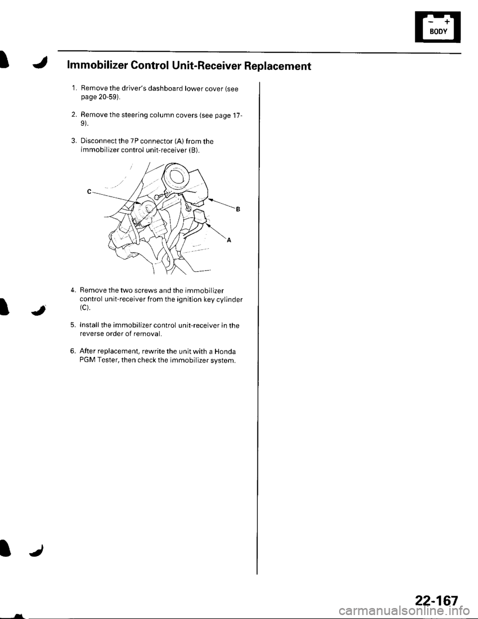
Disconnect the 7P connector (A) from the
immobilizer control unit-receiver (B).
5.
Remove the two screws and the immobilizer
control unit-receiver from the ignition key cylinder(c).
Install the immobilizer control unit-receiver in the
reverse order of removal.
After replacement, rewrite the unit with a Honda
PGM Tester, then check the immobilizer system.
JI
6.
-___-l-
22-167
Page 1003 of 1139
Multiplex Control System
Troubleshooting
Mode 1 Tset
1. Remove the driver's dashboard lower cover {see
page 20-59).
2. Check the No. 9 ( 10A) fuse in the under-hood fuse/
relay box and the No. 10 (7.5A) fuse in the under-
dash fuse/relay box.
Are the fuses OK?
YES-Go to step 2.
NO-Find and repairthe cause ofthe blown fuse.!
3. Turn the ignition switch ON (ll).lf the driver's
seatbelt is unbuckled the seat belt reminder will
chime 6 times.
4. Set the ceiling light to the center position and close
allthe doors.
5. Connect the specialtoolto the multiplex inspection
conneclor.
6. After about 5 seconds the spotlight and ceiling light
should come on for 2 seconds, go out, then blink on
for 0.2 second to show the system is now in mode
1.
Did the spotlight and ceiling light indicate mode
1?
YES-Go to step 8.
NO Go to step 7.
22-172
-
7. Check for continuity between terminal 4ofthe
under-dash fuse/relay box connector J and body
ground.
ls there continuity?
YES Replace the under-dash fuse/relay box.l
NO - Repair the open in the wire.lf the wire is ok,
repair G301.1
8. lf ther are any DTCS present, the spotlight and
ceiling light will blink to indicate the DTC(S). lf more
than one DTC is present, the DTCS will be displayed
in ascending order, lf there are no DTCS the
spotlight and ceiling light will not blink again after
the mode 1 indication.
Are there any DTCg?
YES Go to step 9.
NO Go to the Mode 2 test.
9. Troubleshoot the DTC(S) in the order indicated
using the following charts.
lf a faulty control unit is suspected, substitute it
with a known food part and recheck for DTCS,
. lf the DTC(s) isstill present. go to the next step
listed for the DTC.. lf the DTC(S) is no longer present replace the
original part.
Page 1006 of 1139
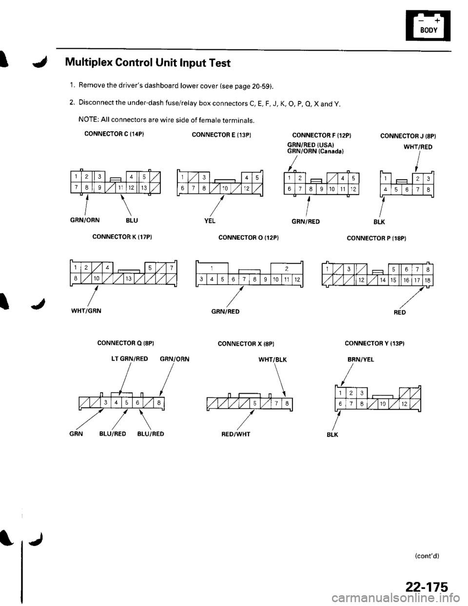
IMultiplex Control Unit Input Test
Remove the driver's dashboard lower cover (see page 20-59).
Disconnect the under-dash fuse/relay box connectors C, E, F, J, K, O, p, O, X and y.
NOTE: All connectors are wire side of female terminals.
CONNECTOR C {14P}CONNECTOR E I13P)
1.
2.
CONNECTOR F {12P}
GRN/RED {USAIGRN/ORN (Canada)
coNNECTOR P (18P)
CONNECTOR J {8PI
WHT/RED
123
4561
BLK
{cont'd)
GRN/ORN BLU
CONNECTOR K {17P)
I
CONNECTOR O I12P)
CONNECTOR X {8P)CONNECTOR O (8P}
LT GRN/RED GRN/ORN
CONNECTOR Y {13P)
BRN/YEL
BLU/REDBLU/RED
345
67E10 )./12
YELGRN/RED
12457
810/V,/ l,/
WHT/GBN
3567I
,/1,/l,/121517
REDGRN/RED
WHT/BLK
RED/WHT
23,/1,/
618r012
BLK
22-175
Page 1028 of 1139
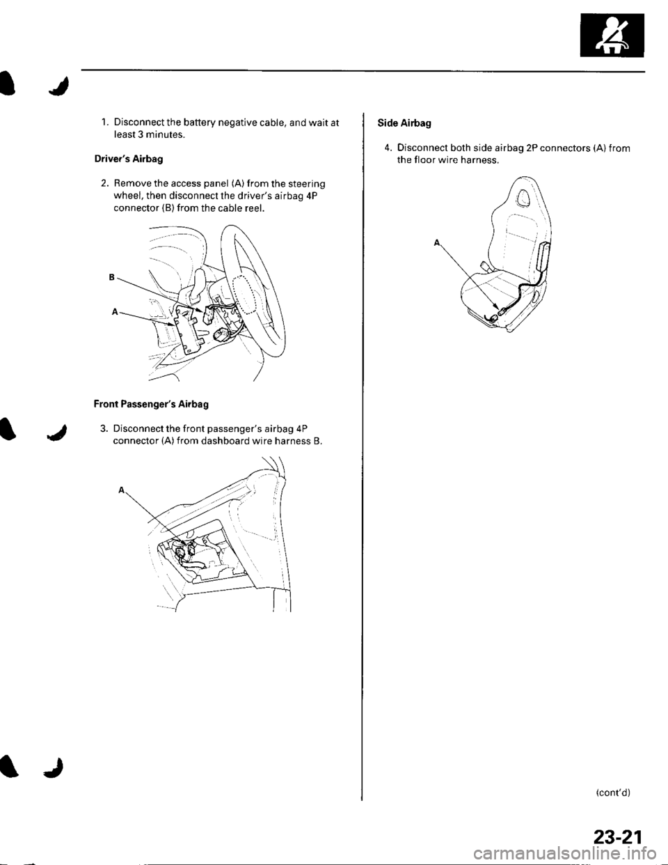
1. Disconnect the battery negative cable, and wait at
least 3 minutes.
Driver's Airbag
2. Remove the access panel (A) from the steering
wheel, then disconnecl the driver's airbag 4P
connector (B)from the cable reer.
Front Passenger's Airbag
3. Disconnect the front passenger's airbag 4P
connector (A)from dashboard wire harness B.
Side Airbag
4. Disconnect both side airbag 2P connectors (Alfrom
the floor wire harness.
(cont'd)
23-21