Steering HONDA CIVIC 2003 7.G Owner's Guide
[x] Cancel search | Manufacturer: HONDA, Model Year: 2003, Model line: CIVIC, Model: HONDA CIVIC 2003 7.GPages: 1139, PDF Size: 28.19 MB
Page 522 of 1139
11.
't2.
Substitute a known-good EPS control unit, and
reconnect the disconnected connectors.
Sta rt the engine.
Does the EPS indicator come on?
YES Go to step 13.
NO Check for loose or poor connections at the
EPS control unit and the torque sensor conneclors.
lf the connections are good, replace the EPS control
unit and recheck.I
Stop the engine, and verify the DTC.
ls DTC16 indicated?
YES Replace the steering gearbox and recheck.l
NO Perform the appropriate troubleshooting for
the code indicated.l
13.
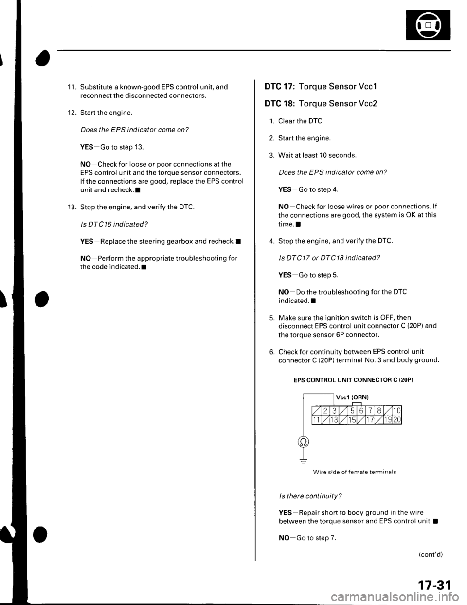
DTC 17: Torque Sensor Vccl
DTC 18: Torque Sensor Vcc2
1. Clear the DTC.
2. Start the engine.
3. Wait at least 10 seconds.
4.
Does the EPS indicator come on?
YES Go to step 4.
NO Check for loose wires or poor connections. lf
the connections are good, the system is OK at this
time.I
Stop the engine, and verify the DTC.
Is DTCl7 or DTCl8 indicated?
YES Go to step 5.
NO Do the troubleshooting for the DTc
indicated.I
Make sure the ignition switch is OFF, then
disconnect EPS control unit connector C (20P) and
the torque sensor 6P connector.
Check for continuity between EPS control unit
connector C (20P)terminal No. 3 and body ground.
EPS CONTROL UNIT CONNECTOR C (2OP)
Wire side o{ female terminals
ls there continuity?
YES Repair shon to body ground in the wire
between the torque sensor and EPS control unit.I
NO Go to step 7.
(cont'd)
17-31
Page 523 of 1139
EPS Components
DTC Troubleshooting (cont'dl
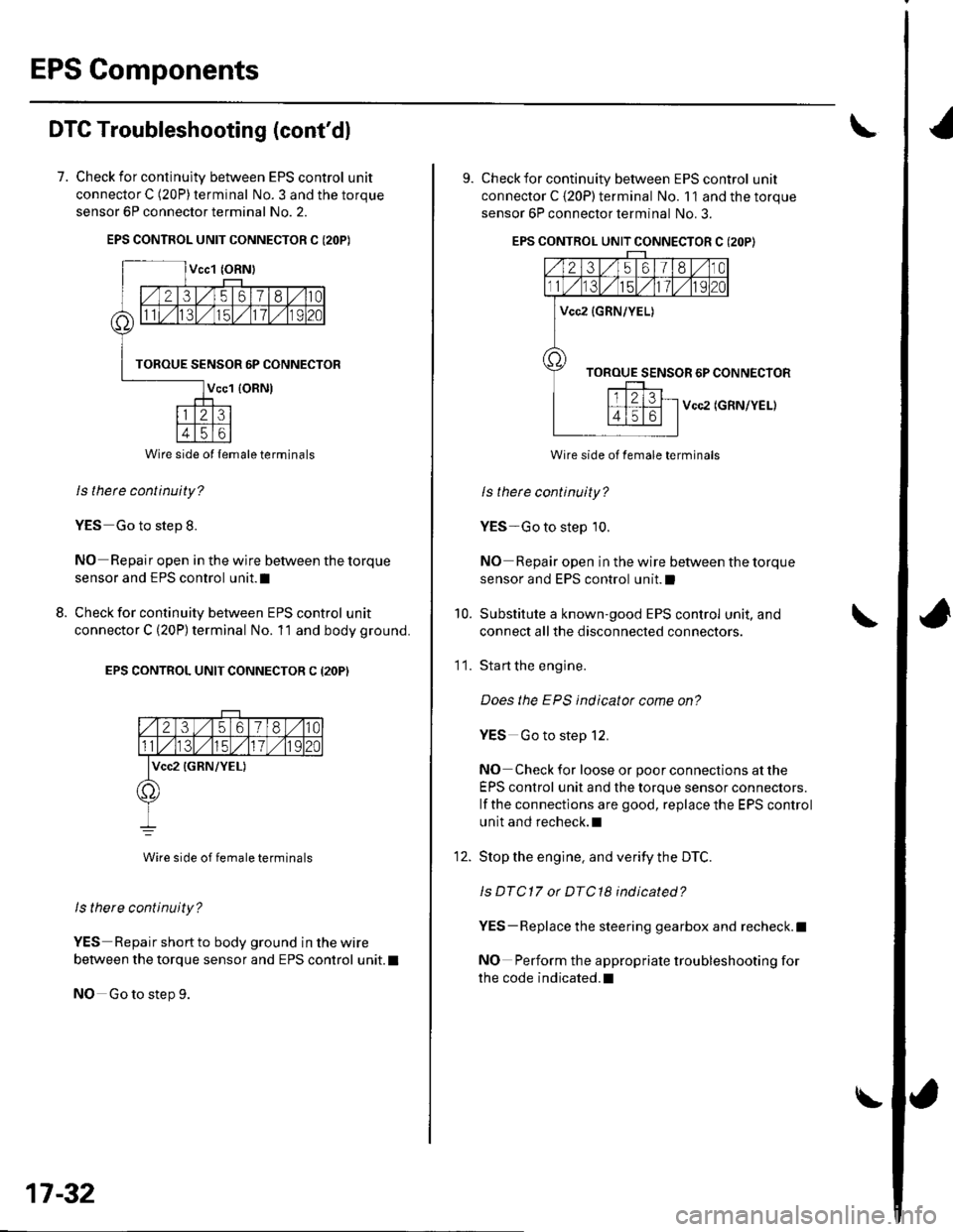
7. Check for continulty between EPS control unit
connector C (20P) terminal No. 3 and the torque
sensor 6P connector terminal No. 2.
EPS CONTROL UNIT CONNECTOR C I2OP)
ls thete continuity?
YES Go to step 8.
NO Repair open in the wire between the torque
sensor and EPS control unit.I
Check for continuity between EPS control unit
connector C (20P) terminal No. 11 and body ground.
EPS CONTROL UNIT CONNECTOR C (2OP)
2356180
lvcc2 {GRN/YEL)
Wire side of female terminals
ls there continuity?
YES Repair short to body ground in the wire
between the torque sensor and EPS control unit. t
NO Go to step 9.
8.
Wire side ol lemale terminals
17-32
\
9. Check for continuity between EPS control unit
connector C {20P) terminal No. 11 and the torque
sensor 6P connector terminal No. 3.
EPS CONTROL UNIT CONNECTOR C (2OP}
Vcc2 (GRN/YEL)
Wire side of female terminals
ls therc continuity?
YES-Go to step 10.
NO Repair open in the wire between the torque
sensor and EPS control unit.l
Substitute a known-good EPS control unit, and
connect all the disconnected connectors.
Sta rt the engine.
Does the EPS indicator come on?
YES Go to step 12.
NO Check for loose or poor connections at the
EPS control unit and the torque sensor connectors.
lf the connections are good, replace the EPS control
unit and recheck.l
Stop the engine, and verity the DTC.
ls DTC17 or DTC18 indicated?
YES-Replace the steering gearbox and recheck.l
NO Perform the appropriate troubleshooting for
the code indicated.l
10.
11.
12.
Page 526 of 1139
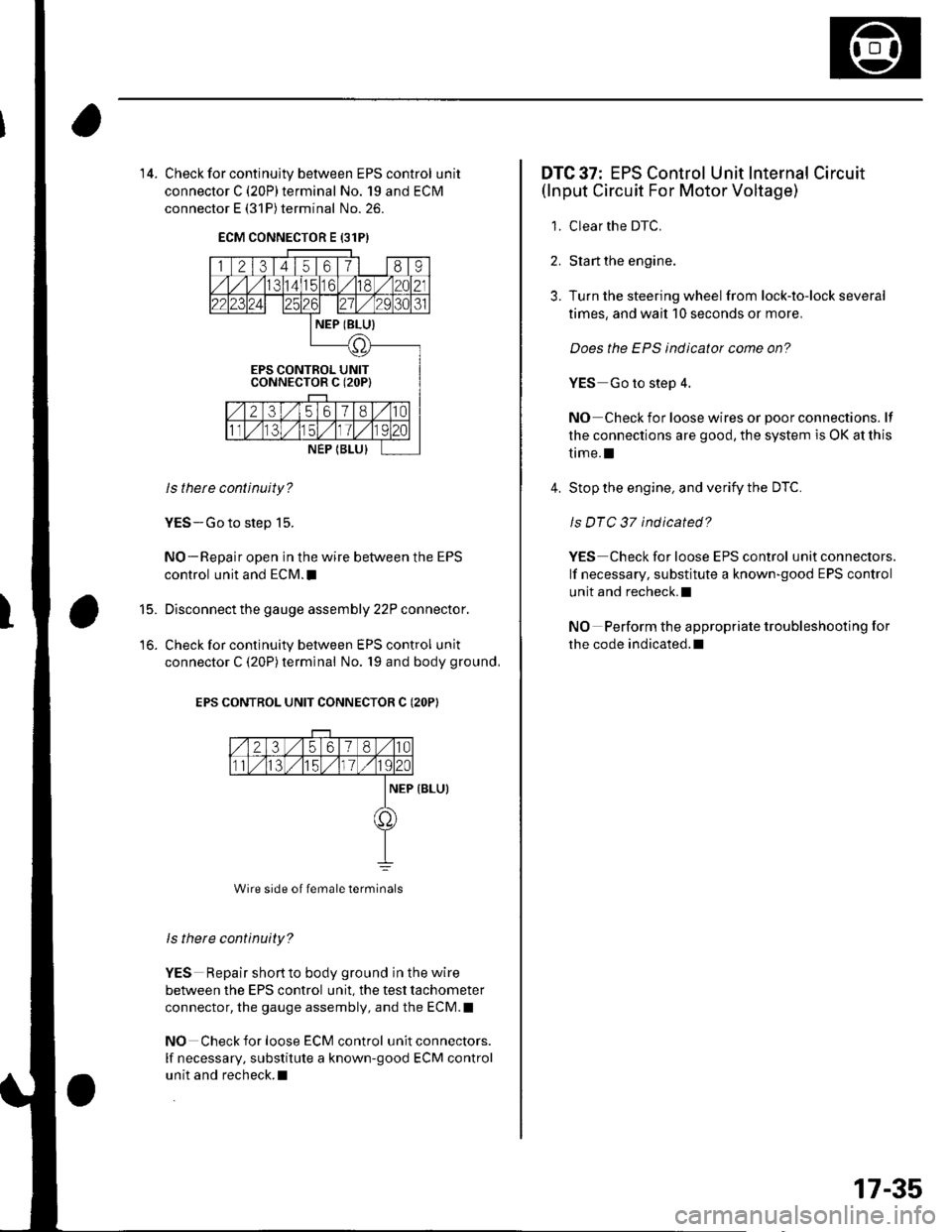
'14. Check for continultv between EPS control unit
connector C (20P)terminal No. 19 and ECM
connector E (31P) terminal No. 26.
ECM CONNECTOR E {31PI
ls thete continuity?
YES-Go to step 15.
NO-Repair open in the wire between the EPS
control unit and ECM.I
Disconnect the gauge assembly 22P connector.
Check for continuity between EPS control unit
connector C (20P)terminal No. 19 and body ground,
EPS CONTROL UNIT CONNECTOR C (2OP}
Wire side of female terminals
ls there continuity?
YES Repair shortto body ground in the wire
between the EPS control unit, the test tachometer
connector, the gauge assembly, and the ECM.I
NO Check for loose ECM control unit connectors.
lf necessary, substitute a known-good ECM control
unit and recheck.I
15.
DTC 37: EPS Control Unit Internal Circuit(lnput Circuit For Motor Voltage)
1. Clear the DTC.
2. Start the engine.
3. Turn the steering wheel from lock-to-lock several
times, and wait 10 seconds or more.
Does the EPS indicator come on?
YES Go to step 4.
NO Check for loose wires or poor connections. lf
the connections are good, the system is OK at this
trme.l
4. Stop the engine, and verify the DTC.
ls DTC 37 indicated?
Y€S Check for loose EPS control unit conneclors.
lf necessary, substitute a known-good EPS control
unit and recheck.l
NO Perform the appropriate troubleshooting for
the code indicated.l
17-35
Page 527 of 1139
EPS Components
DTC Troubleshooting (cont'dl
DTC 41: Voltage For Motor
1. Clear the DTC.
2. Start the engine.
3. Turn the steering wheel from lock-to-lock several
times, and wait 10 seconds or more,
Does the EPS indicator come on?
YES-Go to step 4.
NO Check for loose wires or poor connections. lf
the connections are good, the system is OK at this
time.l
4. Stop the engine, and verify the DTC.
ls DTC 41 indicated?
YES Go to step 5.
NO Perform the appropriate troubleshooting for
the code indicated.l
5. Make sure the ignition switch is OFF, then
disconnect EPS control unit connector B (2P) and
the motor 2P conneclor.
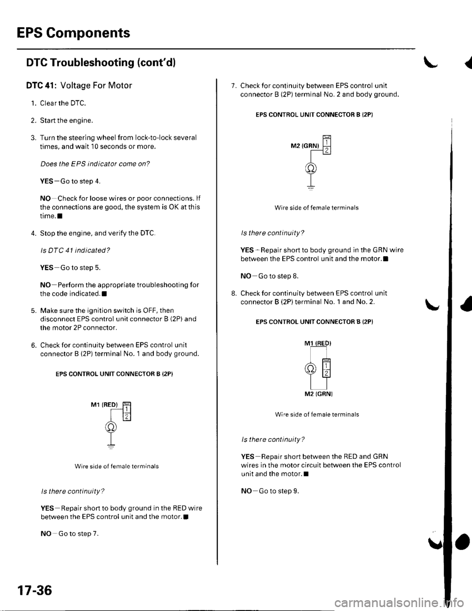
6. Check for continuity between EPS control unit
connector B (2P) terminal No. 1 and body ground.
EPS CONTROL UNIT CONNECTOR B {2P}
M1 (RED} HF---t||
Itr(f))
T,L
Wire side of female terminals
ls there continuity?
YES Repair short to body ground in the RED wire
between the EPS control unit and the motor. !
NO-Go to step 7.
17-36
7. Check for continuity between EPS control unit
connector B (2P)terminal No. 2 and body ground.
EPS CONTROL UNIT CONNECTOR B I2P)
TitM2 {GRN) FJ
-r
o)
TI
Wire side of female terminals
ls there continuity?
YES-Repair short to body ground in the GRN wire
between the EPS control unit and the motor,l
NO Go to step 8.
Check for continuity between EPS control unit
connector B (2P)terminal No. 1 and No. 2.
EPS CONTROL UNIT CONNECTOR B {2P)
Wire side of female terminals
ls there continuity?
YES Repair short between the RED and GRN
wires in the motor circuit between the EPS control
unit and the motor.l
NO Go to step 9.
M2 (GRNI
.l
\
Page 528 of 1139
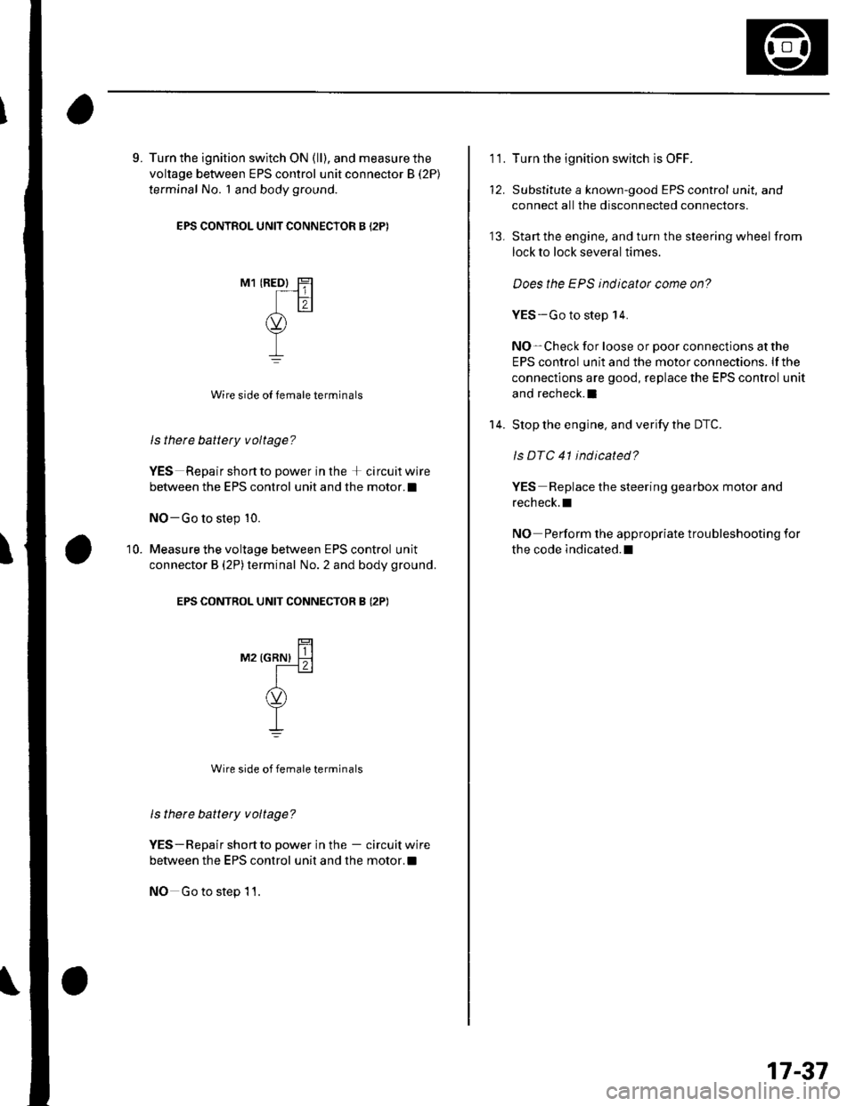
9. Turn the ignition switch ON (ll), and measure the
voltage between EPS control unit connector B (2P)
terminal No. 1 and body ground
EPS CONTROL UNIT CONNECTOR B (2P)
M1 IREDI Hr-_ -1 ||
tr,<.)\uL,/Y
I
Wire side oI female terminals
Is there battety voltage?
YES Repair short to power in the + circuit wire
between the EPS control unit and the motor.I
NO-Go to step 10.
Measure the voltage between EPS control unit
connector B (2P)terminal No.2 and body ground.
EPS CONTROL UNIT CONNECTOR B (2P)
10.
raz rcnrrrr l{l-t . I
I(v)
YI
Wire side of female terminals
ls there battery voltage?
YES-Repair shortto power in the - circuitwire
between the EPS control unit and the motor.!
NO Go to step 11.
11.Turn the ignition switch is OFF.
Substitute a known-good EPS control unit, and
connect all the disconnected connectors.
Start the engine, and turn the steering wheel from
lock to lock several times.
Does the EPS indicator come on?
YES-Go to step 14.
NO-Check for loose or poor connections atthe
EPS control unit and the motor connections. lfthe
connections are good, replace the EPS control unit
and recheck.l
Stop the engine, and verity the DTC.
ls DTC 41 ind icated?
YES Replace the steering gearbox motor and
recheck.l
NO Perform the appropriate troubleshooting for
the code indicated.l
13.
14.
17-37
Page 529 of 1139
EPS Components
{DTC Troubleshooting (cont'd)
DTC 42,45: Motor Driven Current
1. Clear the DTC.
2. Sta rt the engine.
3. Turn the steering wheel from lock-to-lock several
times, and wait 10 seconds or more.
Does the EPS indicator come on?
YES- Go to step 4.
NO-Check for loose wires or poor connections. lf
the connections are good, the system is OK at this
time.I
Stop the engine, and verify the DTC.
ls DTC 42 or 45 indicated?
YES-Go to step 5.
NO- Perform the appropriate troubleshooting for
the code indicated.I
Make sure the ignition switch is OFF, then
disconnect EPS control unit B connector (2P) and
the motor 2P connector.
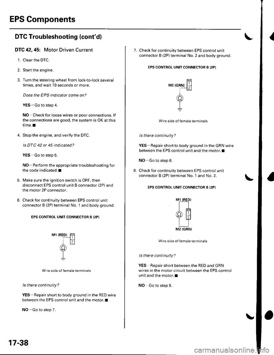
Check for continuity between EPS control unit
connector B (2P)terminal No. 1 and body ground.
EPS CONTROL UNIT CONNECTOR B I2P)
M1 IRED} H
I f2-l
(C))
TI
Wire side of female terminals
ls there continuity?
YES Repair short to body ground in the RED wire
between the EPS control unit and the motor,I
NO-Go to step 7.
6.
17-38
7. Check for continuity between EPS control unit
connector B (2Plterminal No.2 and body ground.
EPS CONTROL UNIT CONNECTOR B I2PI
r',rz tcnnrt ll
-]-(o)
TI
Wire side of female terminals
lsthere continuity?
YES Repair short to body ground in the GRN wire
between the EPS control unit and the motor.l
NO Go to step 8.
Check for continuity between EPS control unit
connector B (2P) terminal No. 1 and No. 2.
EPS CONTROL UNIT CONNECTOR B {2P)
Wire side of female terminals
ls there continuity?
YES Repair short between the RED and GRN
wires in the motor circuit between the EPS control
unit and the motor.l
NO Go to step 9.
M2 {GRN)
Page 531 of 1139
EPS Gomponents
DTG Troubleshooting (cont'd)
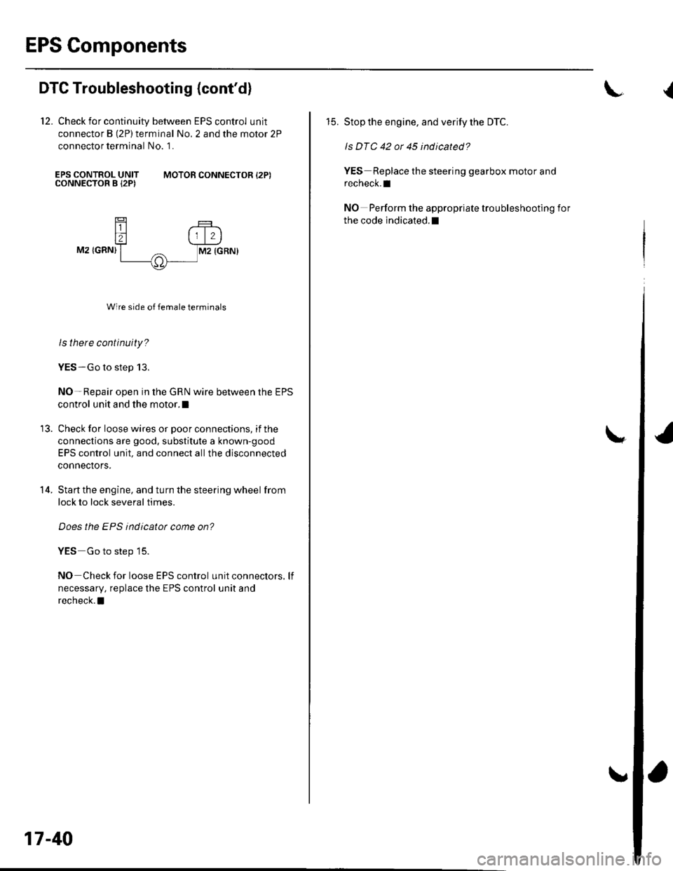
12. Check for continuity between EPS control unit
connector B (2P)terminal No. 2 and the motor 2P
connector terminal No. 1.
EPS CONTROL UNITCONNECTOR B I2PIMOTOR CONNECTOR {2P)
14.
M2 IGRN)
Wire side of female terminals
ls there continuity?
YES-Go to step 13.
NO-Repair open in the GRN wire between the EPS
control unit and the motor.l
Check for loose wires or poor connections, if the
connections are good. substitute a known-good
EPS control unit, and connect allthe disconnected
connectors.
Start the engine, and turn the steering wheel from
lock to lock several times.
Does the EPS indicatot come on?
YES Go to step 15.
NO Check for loose EPS control unitconnectors. lf
necessary, replace the EPS control unit and
recheck. a
17-40
L
15. Stop the engine, and verify the DTC.
ls DTC 42 or 45 indicated?
YES Replace the steering gearbox motor and
recheck.l
NO Perform the appropriate troubleshooting for
the code indicated.l
(
Page 532 of 1139
DTC tli|: Motor Driven Current is Excessively
Hish
1. Clear the DTC.
2. Start the engine.
3. Turn the steering wheel from lock-to-lock several
times, and wait '10 seconds or more.
Does the EPS indicator come on?
YES Go to step 4.
NO-Check for loose wires or poor connections. lf
the connections are good, the system is OK at this
ttme.I
4. Stop the engine, and verify the DTC.
ls DTC 43 indicated?
YES Go to step 5.
NO-Perform the appropriate troubleshooting for
the code indicated.I
5. Make sure the ignition switch is OFF, then
disconnect EPS control unit connector B (2P) and
the motor 2P connector.
6. Turn the ignition switch ON (ll).
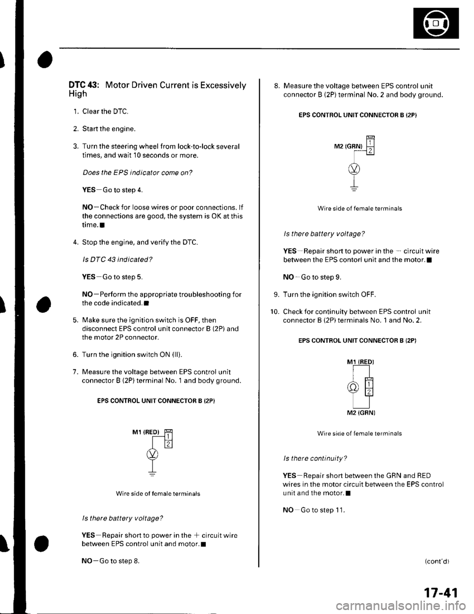
7. Measure the voltage between EPS control unit
connector B (2P)terminal No. '1 and body ground.
EPS CONTROL UNIT CONNECTOR B {2P}
M1 {REo) HT------t I I
Itr(v)
T-L
Wire side ot Iemale terminals
ls therc battery voltage?
YES Repair short to power in the + circuit wire
between EPS control unit and motor.l
NO-Go to step 8.
8. Measure the voltage between EPS control unit
connector B (2P)terminal No. 2 and body ground.
EPS CONTROL UNIT CONNECTOR B I2PI
TilM2 tcRNl F-lf---1 z I
(v)
Y
I
Wire side of female terminals
ls there battety voltage?
YES- Repair short to power in the - circuit wire
between the EPS contorl unit and the motor. !
NO-Go to step 9.
Turn the ignition switch OFF.
Check for continuity between EPS control unit
connector B (2P) terminals No. 1 and No. 2.
EPS CONTROL UNIT CONNECTOR B {2P)
Wire side of female terminals
ls there continuity?
YES Repair short between the GRN and RED
wires in the motor circuit between the EPS control
unit and the motor.l
NO Gotostep 11.
9.
10.
(cont d)
17-41
M2 {GBN)
Page 533 of 1139
EPS Components
11.
12.
DTC Troubleshooting (cont'dl
Substitute a known-good EPS control unit, and
connect all the disconnected connectors.
Sta rt the engine, and turn the steering wheel from
lock to lock several times.
Does the EPS indicator come on?
YES Go to step 13.
NO -Check for loose or poor connections at the
EPS control unit and the motor connections. lf the
connections are good, replace the EPS control unit
and recheck.l
Stop the engine, and verity the DTC.
ls DTC 43 indicated?
YES-Replace the steering gearbox motor and
recheck. tl
NO-Perform the appropriate troubleshooting for
the code indicated.l
13.
17-42
DTC 47: EPS Control Unit lnternal Circuit(Power Relay)
1. Clear the DTC.
2. Start the engine.
Does the EPS indicator come on?
YES-Go to step 3,
NO-Check for loose wires or poor connections, lf
the connections are good, the system is OK at this
time.I
3. Stop the engine, and verify the DTC.
ls DTC 47 indicated?
YES Check for loose EPS control unit connectors.
lf necessary, substitute a known-good EPS control
unit and recheck.l
NO Perform the appropriate troubleshooting for
the code indicated.I
(
Page 536 of 1139
DTC 66,68: EPS Control Unit lnternal Circuit
1. Clear the DTC.
2. Sta rt the engine.
3. Turn the steering wheel from lock-to-lock several
times, and wait 10 seconds or more.
Does the EPS indicator come on?
YES-Go to step 4.
NO-Check for loose wires or poor connections. lf
the connections are good. the system is OK at this
time.l
4. Stop the engine. and verify the DTC.
ls DTC 66 or 68 indicated?
YES-Check for loose or poor connections at the
EPS control unit. lf the conneclions are good,
substitute a known-good EPS control unit. lf the
symptom/indication goes away, replace the
original EPS control unit and recheck.I
NO Perform the appropriate troubleshooting for
the code indicated. t
DTC 67: Torque Sensor l/F Circuit
1. Clear the DTC.
2. Start the engine.
3. Turn the steering wheelfrom lock-to-lock several
times, and wait 10 seconds or more.
Does the EPS indicator come on?
YES-Go to step 4.
NO Check for loose wires or poor connections. lf the
connections are good, the system is OK at this time. !
4. Stop the engine, and verify the DTC.
ls DTC 67 indicated?
YES Check for loose or poor connections at the
EPS control unit. lf the connections are good,
substitute a known-good EPS control unit. lf the
symptom/indication goes away, replace the
original EPS control unit and recheck. !
NO-Perform the appropriate troubleshooting for
the code indicated.I
17-45