ecm HONDA CIVIC 2003 7.G Repair Manual
[x] Cancel search | Manufacturer: HONDA, Model Year: 2003, Model line: CIVIC, Model: HONDA CIVIC 2003 7.GPages: 1139, PDF Size: 28.19 MB
Page 272 of 1139
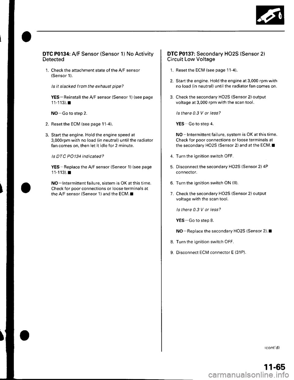
DTC P0134: Ay'F Sensor (Sensor 1) No Activity
Detected
1. Check the attachment state of the A,/F sensor(Sensor 1).
ls it slacked f rom the exhaust pipe?
YES- Reinstall the Ay'F sensor (Seneor 1) (see page
11-113).t
NO-Go to step 2.
2. Reset the ECM (see page 1 1-4).
3. Stan the engine. Hold the engine speed at
3,000rpm with no load (in neutral) until the radiator
fan comes on, then let it idle for 2 minute.
ls DTC PO134 indicated?
YES-Replace the Ay'F sensor {Seneor 1) (see page
11-113).t
NO - Intermittent failu re, sistem is OK at this time.
Check for poor connections or loose terminals at
the Ay'F sensor (Seneor 1 ) and the ECM.I
DTC P0137: Secondary HO2S (Sensor 2)
Circuit Low Voltage
1. Reset the ECM (see page I1-4)
2. Start the engine. Hold the engine at 3,000 rpm wilh
no load (in neutral) until the radiator fan comes on.
3. Check the secondary HO2S (Sensor 2) output
voltage at 3,000 rpm with the scan tool.
ls there 0.3 V or less?
YES Go to step 4.
NO-lntermittent failure, system is OK at this time.
Check for poor connections or loose terminals at
the secondary HO2S (Sensor 2) and at the ECM.I
Turn the ignition switch OFF.
Disconnect the secondary HO2S (Sensor 2) 4P
connector.
Turn the ignition switch ON (ll).
Check the secondary HO2S (Sensor 2) output
voltage with the scan tool.
ls there 0.3 V or less?
YES Go to step 8.
NO Replace the secondary HO2S (Sensor 2).1
Turn the ignition switch OFF.
Disconnect ECM connector E (31P).
icont'd)
4.
5.
6.
7.
8.
9.
11-65
Page 273 of 1139
PGM-FISystem
aDTC Troubleshooting (cont'dl
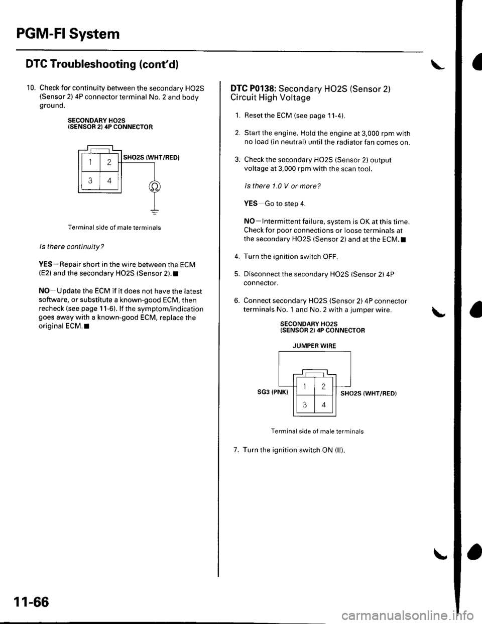
10. Check for continuity between the secondary HO2S(Sensor 2) 4P connector terminal No. 2 and bodygrou nd.
SECONDARY H02SISENSOR 2) 4P CONNECTOR
Terminal side of male terminals
ls there continuity?
YES-Repair shon in the wire between the ECM(E2) and the secondary HO2S (Sensor 2). t
NO Update the ECM if it does not have the latest
software, or substitute a known-good ECM, then
recheck (see page 1 1-6). lf the symptom/indication
goes away with a known-good ECM, replace the
original ECM.I|
11-66
DTC P0138: Secondary HO2S (Sensor 2)
Circuit High Voltage
1. Resetthe ECM {see page'11-4).
2. Startthe engine. Hold the engine at 3,000 rpm with
no load (in neutral) until the radiator fan comes on.
3. Check the secondary HO2S (Sensor 2) output
voltage at 3,000 rpm with the scan tool.
ls thete 1.0 V or morc?
YES Go to step 4.
NO-lntermittent failure, system is OK at this time.
Check for poor connections or loose terminals at
the secondary HO2S (Sensor 2) and at the ECM.I
4. Turn the ignition switch OFF.
5. Disconnect the secondary HO2S (Sensor 2) 4P
connector.
Connect secondary H02S (Sensor 2) 4P connector
terminals No. 1 and No. 2 with a jumper wire.
SECONDARY HO2S{SENSOR 2) 4P CONNECTOR
JUMPER WIRE
SG3 (PNKISHO25 (WHT/RED)
Terminal side oJ male terminals
7. Turn the ignition switch ON (ll).
Page 274 of 1139
8.Check the secondary H02S (Sensor 2) output
voltage with the scan tool,
ls there 1.0 V ot mote?
YES-Go to step 9.
NO Replace the secondary HO2S (Sensor 2).1
Turn the ignition switch OFF.
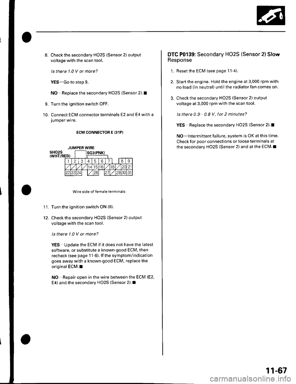
Connect ECM connector terminals E2 and E4 with a
JUmper wrre.
ECM CONNECTOR E 131PI
Wire side of female terminals
Turn the ignition switch ON (ll).
Check the secondary HO2S (Sensor 2) output
voltage with the scan tool.
ls there 1.0 V or more?
YES Update the ECM if it does not have the latest
soflware, or substitute a known-good ECM, then
recheck (see page 1 1-6). lf the symptom/indication
goes away with a known-good ECM. replace the
original ECM.I
NO Repair open in the wire between the ECM (E2,
E4) and the secondary HO2S {Sensor 2).I
9.
10.
11.
12.
JUMPER WIRE
3.
DTC P0139: Secondary HO2S (Sensor 2l Slow
Response
1. Resetthe ECM (see page 11-4).
Start the engine. Hold the engine at 3,000 rpm with
no load (in neutral) until the radiator fan comes on.
Check the secondary HO2S (Sensor 2) output
voltage at 3,000 rpm with the scan tool.
ls thete 0.3- 0.8 V, fot 2 minutes?
YES Replace the secondary HO2S (Sensor 2).!
NO- lntermittent failure, system is OK at this time.
Check for poor connections or loose terminais at
the secondary HO2S (Sensor 2) and at the ECM.I
11-67
Page 275 of 1139
PGM-FISystem
3.
DTC Troubleshooting (cont'dl
DTC P0141: Secondary HO2S (Sensor 2l
Heater Circuit Malfunction
1. Reset the ECM (see page 1 l-4)
2. Start the engine.
ls DTC P0141 indicated?
YES-Go to step 3.
NO-lntermittent failure, system is OK at this time.
Check for poor connections or loose terminals at
the secondary HO2S (Sensor 2) and at the ECM.I
Turn the ignition switch OFF.
Disconnect the secondary H02S (Sensor 2) 4P
connecror.
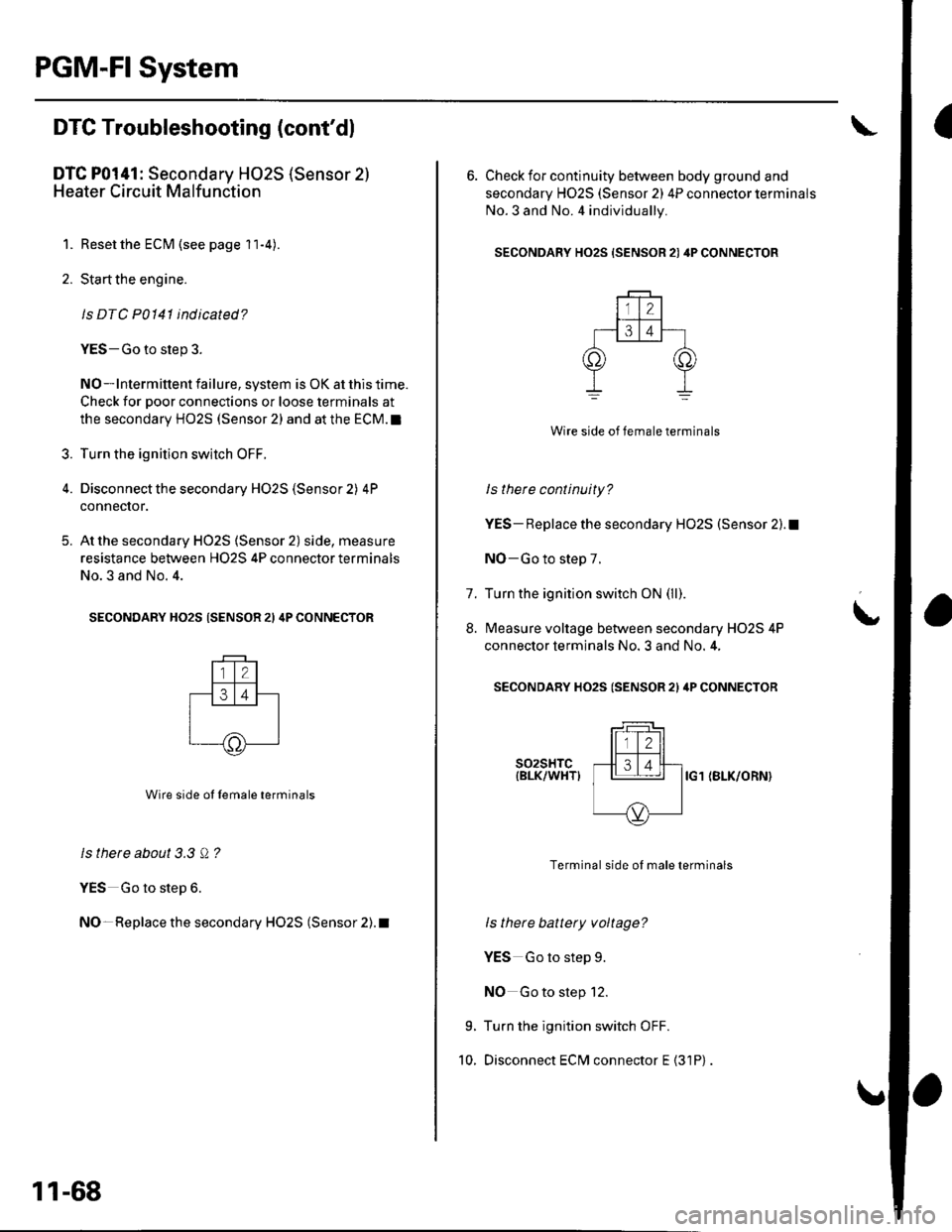
At the secondary HO2S (Sensor 2) side, measure
resistance between H02S 4P connector terminals
No.3 and No. 4.
SECONDARY HO2S (SENSOR 21 4P CONNECTOR
Wire side ol lemale terminals
ls there about 3.3 Q ?
YES Go to step 6.
NO- Replace the secondary HO2S (Sensor 2). t
5.
11-68
6. Check for continuity between body ground and
secondary H02S (Sensor 2) 4P connector terminals
No.3 and No. 4 individually.
SECONDARY HO2S {SENSOR 21 4P CONNECTOR
Wire side of female terminals
ls there continuity?
YES- Replace the secondary HO2S (Sensor 2).1
NO-Go to step 7.
Turn the ignition switch ON (ll).
Measure voltage between secondary H02S 4P
connector terminals No. 3 and No. 4,
SECONDARY HO2S (SENSOR 2l ilP CONNECTOR
t
7.
8.
9.
10.
s02sHTc{BLK/WHTIIG1 (BLK/ORN}
Terminal side of male terminals
ls there battery voltage?
YES Go to step 9.
NO Go to step 12.
Turn the ignition switch OFF.
Disconnect ECM connector E {31P)
Page 276 of 1139
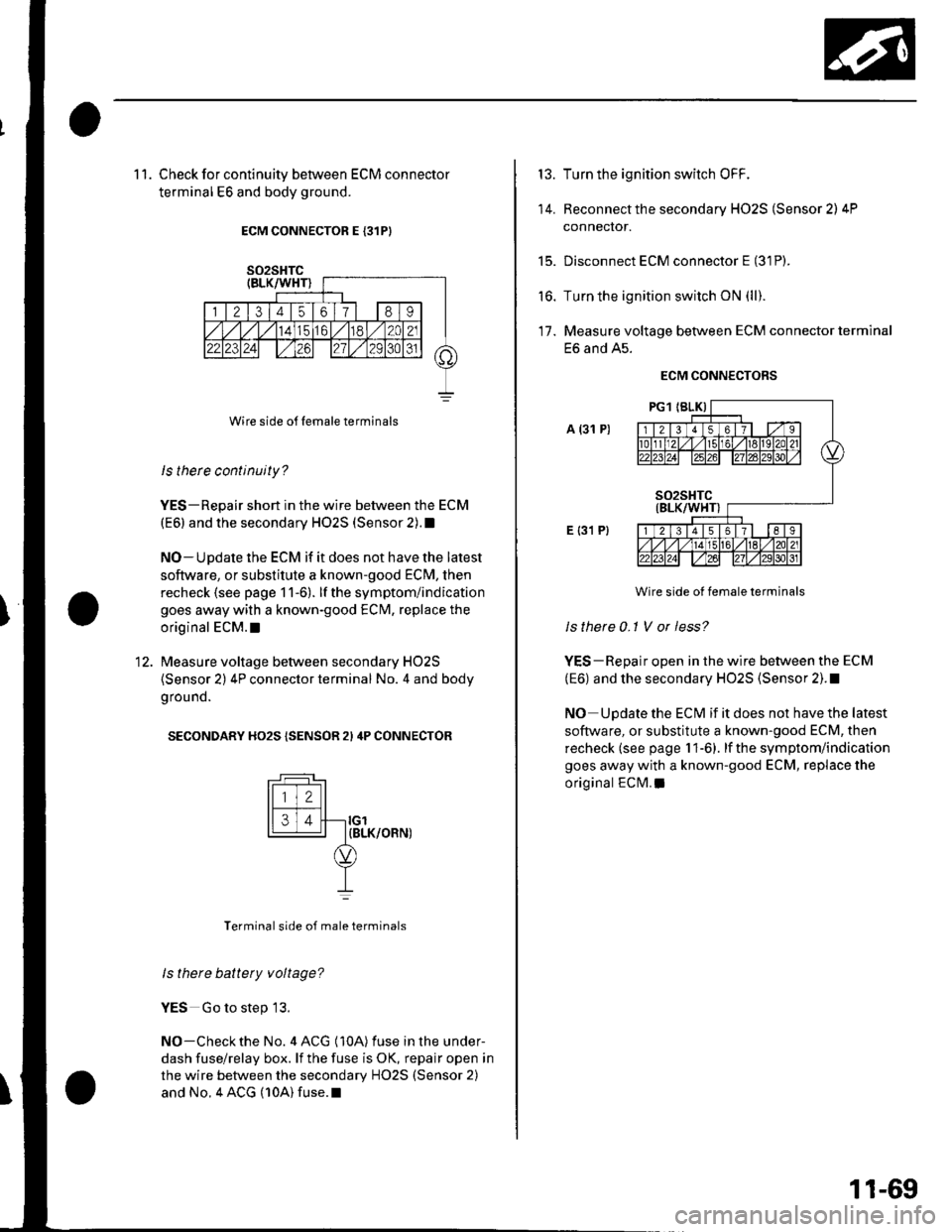
1 1. Check for continuity between ECM connector
terminal E6 and body ground.
ECM CONNECTOR E {31PI
Wire side o{f Iemale terminals
ls therc continuity?
YES-Repair short in the wire between the ECM
(E6) and the secondary HO2S (Sensor 2).1
NO-Update the ECM if it does not have the latest
soflware, or substitute a known-good ECM, then
recheck (see page 1 1-6). lf the symptom/indication
goes away with a known-good ECM, replace the
original ECM.I
Measure voltage between secondary HO2S
(Sensor 2) 4P connector terminal No. 4 and body
g rou nd.
SECONDARY HO2S {SENSOR 2I 4P CONNECTOR
tFff I
l[faJl--ro'14 | IBLK/OFN)
YI
Terminal side of male terminals
ls there battety voltage?
YES Go to step 13.
NO-Checkthe No. 4 ACG (10A) fuse in the under-
dash fuse/relay box. lf the fuse is OK, repair open in
the wire between the secondary HO2S (Sensor 2)
and No. 4 ACG (10A) fuse.l
13.
14.
t5.
to.
Turn the ignition switch OFF.
Reconnect the secondary HO2S (Sensor 2) 4P
connector.
Disconnect ECM connector E (31P).
Turn the ignition switch ON (ll).
Measure voltage between ECM connector terminal
E6 and A5.
ECM CONNECTORS
A (31 P)
E {31 P}
Wire side ot female terminals
Is there 0-1 V or less?
YES-Repair open in the wire between the ECM
(E6) and the secondary HO2S (Sensor 2). !
NO Update the ECM if it does not have the latest
software, or substitute a known-good ECM, then
recheck (see page 1 1-6). lf the symptom/indication
goes away with a known-good ECM, replace the
original ECM. a
17.
11-69
Page 279 of 1139
PGM-FI System
IDTC Troubleshooting (cont'dl
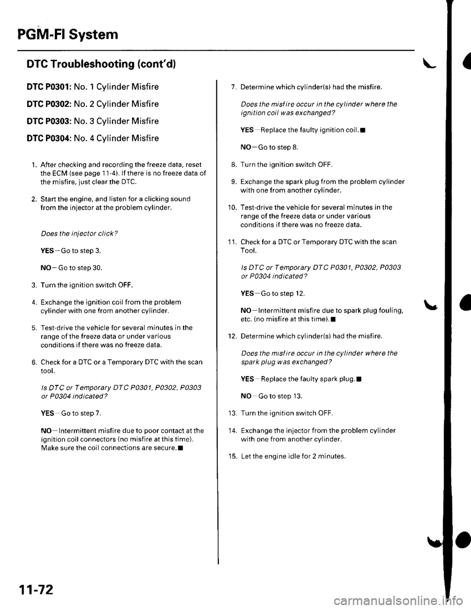
DTC P0301: No. 1 Cylinder Misfire
DTC P0302: No. 2 Cylinder Misfire
DTC P0303: No. 3 Cylinder Misfire
DTC P0304: No. 4 Cylinder Misfire
1. After checking and recording the freeze data, reset
the ECM (see page 1 1-4). lf there is no freeze data of
the misfire, just clear the DTC.
2. Start the engine, and listen for a clicking sound
from the injector at the problem cylinder.
Does the injector click?
YES-Go to step 3.
NO-Go to step 30.
3. Turn the ignition switch OFF.
4. Exchange the ignition coil from the problem
cylinder with one from another cylinder,
5. Test-drive the vehicle for several minutes in the
range of the freeze data or under va rious
conditions if there was no freeze data.
6. Check for a DTC or a Temporary DTC with the scan
root.
ls DTC or Tempotaty DTC P0301, P0302, P0303
or P0304 ind icated?
YES Go to step 7.
NO Intermittent misfire due to poor contact at the
ignition coil connectors {no misfire at this time).
Make sure the coil connections are secure.l
11-72
8.
9.
1.
11.
Determine which cylinder(s) had the misfire.
Does the misf ire occur in the cylinder where the
ignition coil was exchanged?
YES Replace the faulty ignition coil.!
NO-Go to step 8.
Turn the ignition switch OFF.
Exchange the spark plug from the problem cylinder
with one from another cylinder.
Test-drive the vehicle for several minutes in the
range of the freeze data or under various
conditions if there was no freeze data.
Check for a DTC or Temporary DTC with the scan
Tool.
ls DTC ot Tempotary DTC P0301, P0302, P0303
or P0304 ind icated?
YES Go to step 12.
NO Intermittent misfire due to spark plug fouling,
etc. (no misfire at this time).1
Determine which cylinder(s) had the misfire.
Does the misl ire occur in the cylinder where the
spark plug was exchanged?
YES Replace the faulty spark plug.l
NO Go to step 13.
Turn the ignition switch OFF.
Exchange the lnjector from the problem cylinder
with one from another cylinder.
Let the engine idle for 2 minutes.
10.
14.
t5.
Page 280 of 1139
16.Test-drive the vehicle for several minutes in the
range of the freeze data or under various
conditions if there was no freeze data.
Check for a DTC or a Temporary DTC with the scan
Tool.
ls DTC or Temporary DTC P0301, P0302, P0303
or P0304 indicated?
YES Go to step 18.
NO lntermittent misfire due to bad contact at the
injector connector (no misfire at this time). Make
sure the injector connection is secure. Check for
poor connections or loose terminals at the
injector.l
Determine which cylinder(s) had the misfire.
Does the misf ire occur in the cylinder where the
i njector w as exchanged ?
YES- Replace the faulty injector.I
NO-Go to step 19.
Turn the ignition switch OFF.
Disconnect the ignition coil 3P connector from the
problem cylinder.
Turn the ignition switch ON (ll).
't7 .
18.
19.
20.
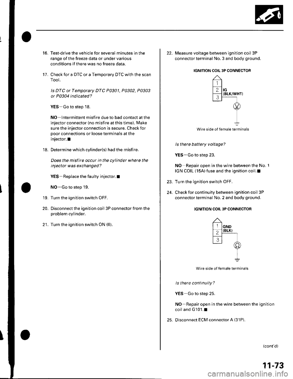
22. Measure voltage between ignition coil 3P
connector terminal No. 3 and body ground.
IGNITION COIL 3P CONNECTOR
Wire side ol female terminals
ls there battery voltage?
YES-Go to step 23.
NO Repair open in the wire between the No. 1
IGN COIL (15A)fuse and the ignition coil.I
Turn the ignition switch OFF.
Check for continuity between ignition coil 3P
connector terminal No. 2 and body ground.
IGNITION COIL 3P CONNECTOR
Wire side ot female terminals
ls there continuity?
YES Go to step 25.
NO Repair open in the wire between the ignition
coiland G101.1
Disconnect ECM connector A {31P)
23.
24.
(cont'd)
11-73
Page 281 of 1139
PGM-FI System
aDTC Troubleshooting (cont'dl
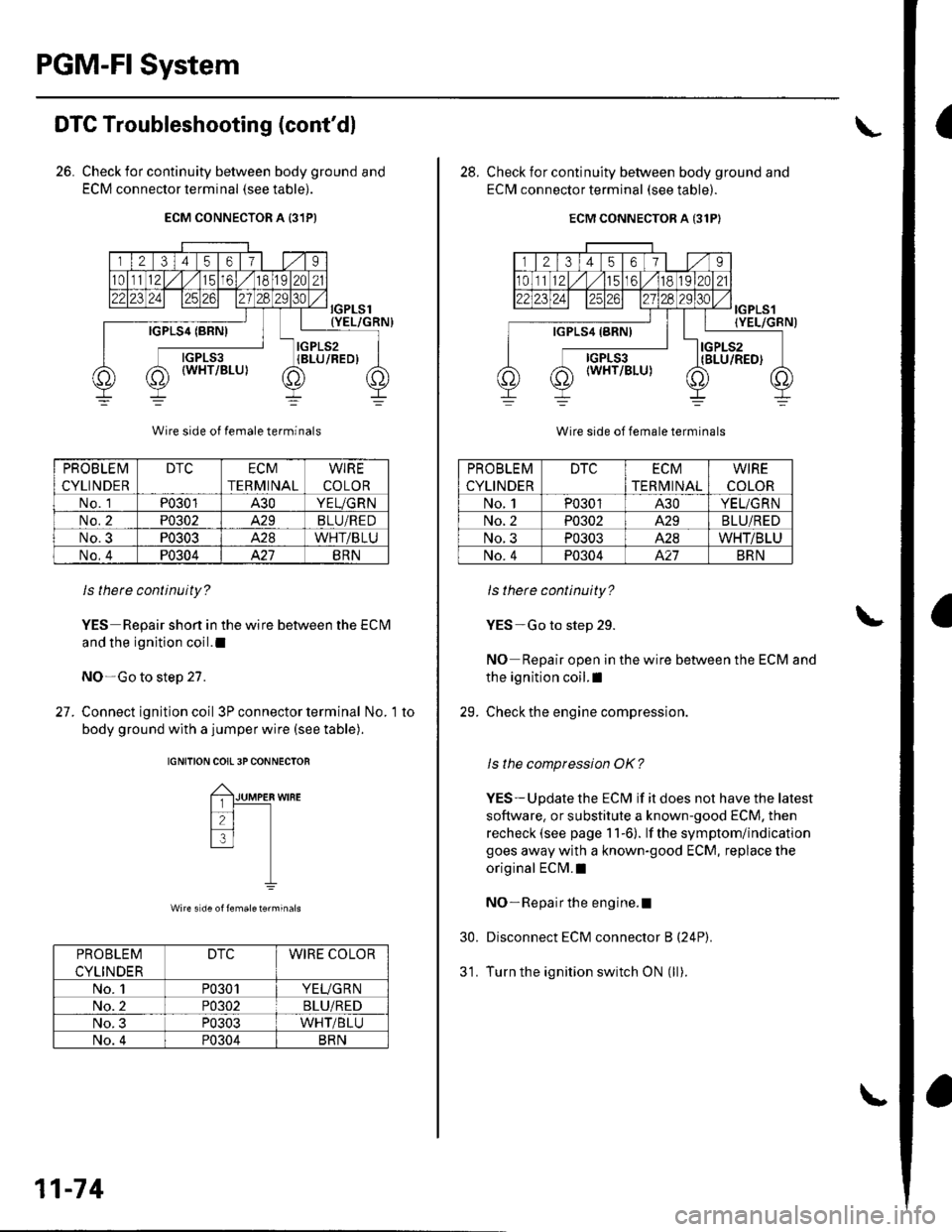
26. Check for continuity between body ground and
ECM connector terminal (see table).
ECM CONNECTOR A {31PI
PROB LE IVI
CYLINDER
DTCECM
TERMINAL
WIRE
COLOR
No. 1P0301430YEUGRN
No.2P0302A.29BLU/RED
No.3P0303428WHT/BLU
No,4P0304421BRN
ls there continuity?
YES Repair shon in the wire between the EClvl
and the ignition coil.l
NO-Go to step 27.
27. Connect ignition coil 3P con nector term inal No. 1to
body ground with a jumper wire (see table).
IGNITION COII 3PCONNECTOR
Wire s de of femaleterminals
PROBLEM
CYLINDER
DTCWIRE COLOR
No. 1P0301YEUGR N
No. 2P0302BLU/RED
No. 3P0303WHT/BLU
No. 4P0304BRN
11-74
28. Check for continuity between body ground and
ECM connector terminal (see table).
ECM CONNECTOR A {31P}
PROBLEM
CYLINDER
DTCECM
TERI\4INAL
WIRE
COLOR
No. 1P0301A30YEL/GRN
No. 2P0302429BLU/RED
No. 3P0303A.28WHT/BLU
No. 4P0304A.21BRN
ls there continuity?
YES-Go to step 29.
NO Repair open in the wire between the ECM and
the ignition coil.l
29. Check the engine compression
ls the compression OK?
YES-Update the ECM if it does not have the latest
software, or substitute a known-good ECM, then
recheck (see page 11-6). lf the symptom/indication
goes away with a known-good ECM, replace the
original ECI\4.I
NO- Repair the engine.l
Disconnect ECM connector B (24P).
Turn the ignition switch ON (ll).
30.
Page 282 of 1139
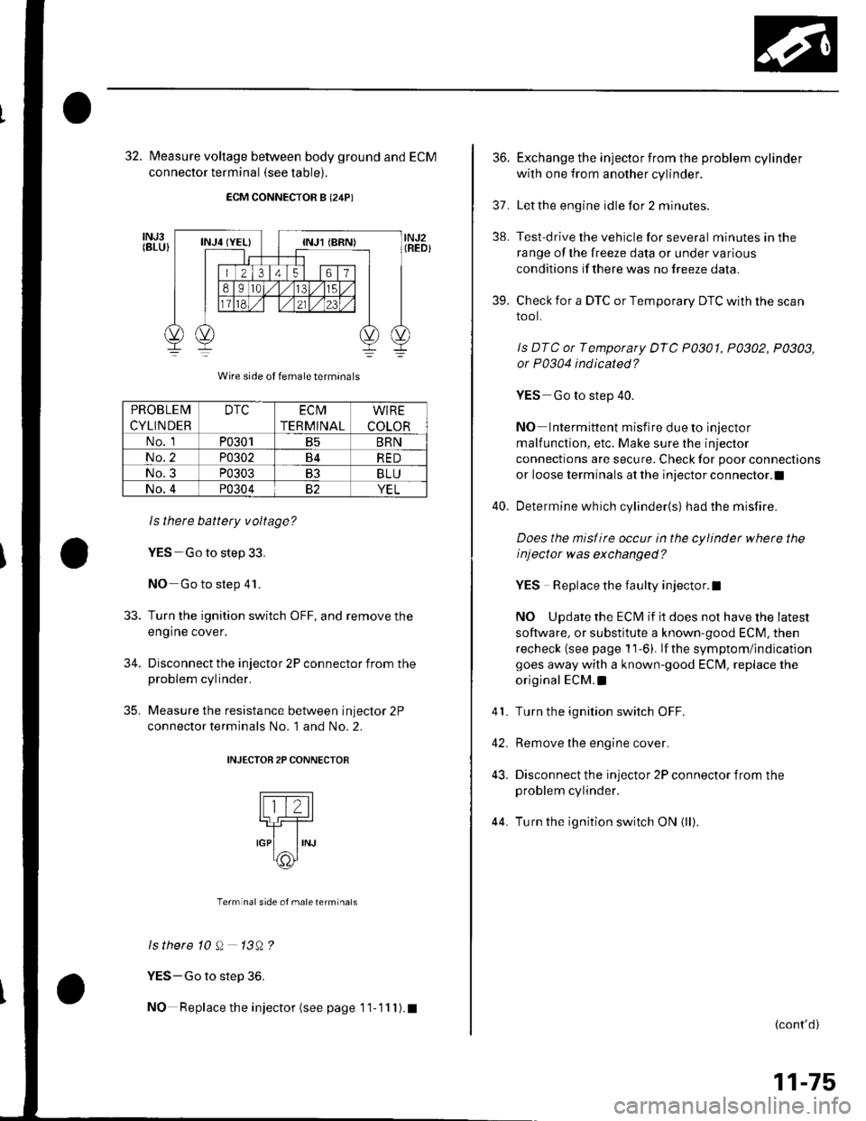
32. fvleasure voltage between body ground and ECM
connector terminal (see table).
ECM CONNECTOR B (24P)
Wire side of female termrnals
ls there battery voltage?
YES-Go to step 33,
NO Go to step 41.
Turn the ignition switch OFF, and remove the
engine cover.
Disconnect the injector 2P connector from theproblem cylinder.
Measure the resistance between injector 2P
connector terminals No. 1 and No. 2.
INJECTOB 2P CONNECTOR
Terminal side of male terminals
ls there 10 Q 13A?
YES-Go to step 36.
NO Replace the injector (see page 1 1- 11 I ). t
33.
34.
35,
PROBLEM
CYLINDER
DTCEC t\4
TERMINAL
WIRE
COLOR
No. 1P0301B5BRN
No.2P0302B4RED
No.3P0303B3BLU
No.4P0304YEL
36.Exchange the injector from the problem cylinder
with one from another cylinder.
Letthe engine idle for 2 minutes.
Test-drive the vehicle for several minutes in the
range oI the lreeze data or under various
condilions if there was no freeze data.
Check for a DTC or Temporary DTC with the scan
tool.
ls DTC or Temporary DTC P0301, P0302, P0303,
or P0304 indicated?
YES Go to step 40.
NO Intermittent misfire due to injector
malfunction, etc. Make sure the injector
connections are secure. Check for poor connections
or loose terminals at the injector connector.l
Determine which cylinder{s} had the misfire.
Does the mislirc occur in the cylinder whete the
i nj ector w as exchanged ?
YES Replace the faulty injector.l
NO Update the ECM if it does not have the latest
software, or substitute a known-good ECM. then
recheck (see page 1 'l-6). lf the symptom/indication
goes away with a known-good EClvl, replace the
original ECM.I
Turn the ignition switch OFF.
Remove the engine cover.
Disconnect the injector 2P connector from the
problem cylinder.
44. Turn the ignition switch ON (ll)
37.
38.
39.
41.
42.
43.
(cont'd)
11-75
Page 283 of 1139
![HONDA CIVIC 2003 7.G Repair Manual PGM-FI System
a
I
DTC Troubleshooting (contdl
45. Measure voltage between injector 2P connector
terminal No. 1 and body ground.
INJECTOR 2P CONNECTOR
tll-z]
,o, ,"=rrrr*, -lt-
oI
Wire side of female HONDA CIVIC 2003 7.G Repair Manual PGM-FI System
a
I
DTC Troubleshooting (contdl
45. Measure voltage between injector 2P connector
terminal No. 1 and body ground.
INJECTOR 2P CONNECTOR
tll-z]
,o, ,"=rrrr*, -lt-
oI
Wire side of female](/img/13/5744/w960_5744-282.png)
PGM-FI System
a
I
DTC Troubleshooting (cont'dl
45. Measure voltage between injector 2P connector
terminal No. 1 and body ground.
INJECTOR 2P CONNECTOR
tll-z]
,o, ,"=rrrr*, -lt-
oI
Wire side of female terminals
ls there battery voltage?
YES-Go to step 46.
NO-Repair open in the wire between the injector
and the PGM-Fl main relay l.l
Turn the ignition switch OFF.
Check for continuity between body ground and
ECM connector terminal (see table).
46.
47.
ECM CONNECTOR B {24P)
Wire side of female terminals
ls there continuity?
YES-Repair short in the wire between the ECM
and the ;njector.I
NO-Go to step 48.
PROBLEM
CYLINDER
DTCECM
TERMINAL
WIRE
COLOR
No. 1P030'1B5BRN
No.2P0302B4RED
No.3P0303B3BLU
No. 4P030482YEL
11-76
48. Connect injector 2P co nnector term inal No.2 to
body ground with a jumper wire {see table).
INJECTOR 2P CONNECTOR
Wire side of {emale terminals
49. Check for continuity between body ground and
ECM connector terminal (see table).
ECM CONNECTOR B I24P)
Wire side oJ temale terminals
ls therc continuity?
YES Replace the injector, then recheck.l
NO Repair open in the wire between the ECM and
the injector.I
tll-Z-l-]_r-l_rNJ
IJUMPER
IwrBE
PROBLEM
CYLINDER
DTCWIRE COLOR
No. 1P0301BRN
No.2P0302RED
No. 3P0303BLU
No. 4P0304YEL
PROBLEM
CYLINDER
DTCECM
TERMINAL
WIRE
COLOR
No. 1P0301B5BRN
No. 2P0302B4RED
No. 3P0303B3BLU
No. 4P030482YEL