ERS HONDA CIVIC 2003 7.G Repair Manual
[x] Cancel search | Manufacturer: HONDA, Model Year: 2003, Model line: CIVIC, Model: HONDA CIVIC 2003 7.GPages: 1139, PDF Size: 28.19 MB
Page 221 of 1139
Fuel and Emissions Systems
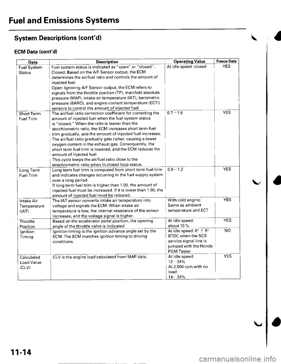
System Descriptions (cont'd)
ECM Data (cont'd)
w
DataDescriptionOpera'ting ValueFreeze Data
Fuel System
Status
Fuel system status is indicated as "open" or "closed".
Closed: Based on the A,/F Sensor output, the ECM
determines the airlfuel ratio and controls the amount of
injected fuel.
Open: lgnoring Ay'F Sensor output, the ECM refers to
signals from the throttle position {TP), manifold absolute
pressure (MAP), intake air temperature (lAT), barometric
pressure (BARO), and engine coolant temperature (ECT))
sensors to control the amount of iniected fuel.
At idle speed: closedYES
Short Term
FuelTrim
The airlfuel ratio correction coefficient for correcting the
amount of injected fuel when the fuel system status
is "closed." When the ratio is leaner than the
sloichiometric ratio, the ECM increases short term fuel
trim gradually, and the amount of iniected fuel increases.
The airlfuel ratio gradually gets richer, causing a lower
oxygen content in the exhaust gas. Consequently, the
short term fuel trim is lowered, and the ECM reduces the
amount of injected fuel.
This cvcle keeps the airlfuel ratio close to the
stoichiometric ratio when in closed loop status.
o.7 1.5YES
Long Term
Fuel Trim
Long term fuel trim is computed from short term fuel trim
and indicates changes occurring in the fuel supply system
over a long period.
lf long term fuel trlm is higher than 1.00, the amounl of
injected fuel must be increased. lf it is lower than 1.00, the
amount of injected fuel must be reduced.
0.8 1.2YES
Intake Air
Temperature
{IAT)
The IAT sensor converts intake air temperature into
voltage and signals the ECM. When intake air
temperature is low, the internal resistance ofthe sensor
increases, and the voltage signal is higher.
With cold engine:
Same as ambient
temperature and ECT
YES
Throttle
Position
Based on the accelerator pedal position, the opening
anole of the throttle valve is indicated.
At idle speed:
about 10 %
YES
lgnition
Timing
lgnition timing is the ignition advance angle set by the
ECM. The ECM matches ignition timing to driving
conditions.
At idle speed: 8" t 5"
|' tuL wnen rne >L)
service signal line is
jumped with the Honda
PGM Tester
NO
Calculated
Load Value
(cLV)
cLV is the enoine load calculated from IMAP data.At idle speed:
12 34%
At 2.500 rpm with no
toao:'t4- 34%
YES
11-14
\.,
ra
Page 223 of 1139
![HONDA CIVIC 2003 7.G Repair Manual Fuel and Emissions Systems
aSystem Descriptions (contdl
ECM Electrical Connections
\
No. INJECTOR
No,2INJECTOR
No.3 INJEC]OB
No./tINJECTOF
MAPSENSON
TPSENSOR
IATSENSOR
ECTSENSOB
\
CMP SENSOR B(TDC S HONDA CIVIC 2003 7.G Repair Manual Fuel and Emissions Systems
aSystem Descriptions (contdl
ECM Electrical Connections
\
No. INJECTOR
No,2INJECTOR
No.3 INJEC]OB
No./tINJECTOF
MAPSENSON
TPSENSOR
IATSENSOR
ECTSENSOB
\
CMP SENSOR B(TDC S](/img/13/5744/w960_5744-222.png)
Fuel and Emissions Systems
aSystem Descriptions (cont'dl
ECM Electrical Connections
\
No. INJECTOR
No,2INJECTOR
No.3 INJEC]OB
No./tINJECTOF
MAPSENSON
TPSENSOR
IATSENSOR
ECTSENSOB
\'
CMP SENSOR B(TDC SENSOSJ
CKPSENSOR
11-16
F€VERSE LOCKSOLENOIDVAIVE
\-
Page 227 of 1139
![HONDA CIVIC 2003 7.G Repair Manual Fuel and Emissions Systems
System Descriptions {contd)
ECM Inputs and Outputs at Connector A (31P)
\. il
Wire side of female terminals
\.
1AFS]TC2
GP2
3IGPl4PG25PG.16AFS+1
CKP
IKS
10SG211sG1
12IACV
HONDA CIVIC 2003 7.G Repair Manual Fuel and Emissions Systems
System Descriptions {contd)
ECM Inputs and Outputs at Connector A (31P)
\. il
Wire side of female terminals
\.
1AFS]TC2
GP2
3IGPl4PG25PG.16AFS+1
CKP
IKS
10SG211sG1
12IACV](/img/13/5744/w960_5744-226.png)
Fuel and Emissions Systems
System Descriptions {cont'd)
ECM Inputs and Outputs at Connector A (31P)
\. il
Wire side of female terminals
\.
1AFS]TC2
GP2
3IGPl4PG25PG.16AFS+1
CKP
IKS
10SG211sG1
12IACV
'15
TPS16AFS_18
VSS
19IVAP20vcc221vccl
22AFSHTC+
23LG225
Ct\.4PA
26CMPB(rDc)
27IGPLS428IGPLS329IGPLS230IGPLS,I
NOTE: Standard battery voltage is 12 V.
JorminalnumberWirecolor[€rminal namoDescriptionSignal
19GRN/REDMAP (MANIFOLDABSOLUTE PRESSURESENSOR)
Detects MAP sensor signalWith ignition switch ON (ll):about3 VAt idle: about 1.0 V (depending on enginespeed)
20YEUBLUVCC2 (SENSOR VOLTAGE)Provides sensor voltageWith ignition switch ON {ll): about 5 VWith ionition switch OFF: about0V21YEUREDVCC] (SENSOB VOLTAGE)Provides sensor voltageWith ignition switch ON {ll): about 5 VWith ionition switch OFF: about0V22AFSHTC - (AIR FUELRATIO (A"iFiSENSORHEATER CONTROL + SIDE)
Detects a,/F sensor heatervoltageWith ign;tion switch ON lll): banery voltage
23BRN?ryE LLG2 (LOGIC GROUNDround for the ECM circuLessthan 1.0 V at alltimes24BRN?ryE L1(Lround for the ECM circuLess than '1.0 V at alltimes25B LU,^/VHTCMP A (CAMSHAFT
POSITION SENSOR A)Detects CMP sensor AstonalWith engine running: pulses
26GRNCMP B CAMSHAFTPOSITION (CMP)SENSOBB (TDC (TOP DEAD CENTERSENSORi)
Detects CMP sensor 8 (TDc
sensor)With engine running: pulses
27BRNIGPLS4 {No. 4IGNITIONCOIL PULSE)Drives No, 4 ignition coiWith ignition switch ON (ll)r about 0 vWith engine running: pulses28WHT/BLUIGPLS3 {No.3IGNITIONCOIL PULSE)Orives No.3 rgnition coi
29BLU/REDlGPLS2lNo.2 IGNITIONCOIL PTJLSE)Drives No.2 ignition coil
30YEUGRNIGPLSI (No. 1 IGNITIONco
PlltsF)Drives No. I ignition coil
11-20
\.
a
a
Page 228 of 1139
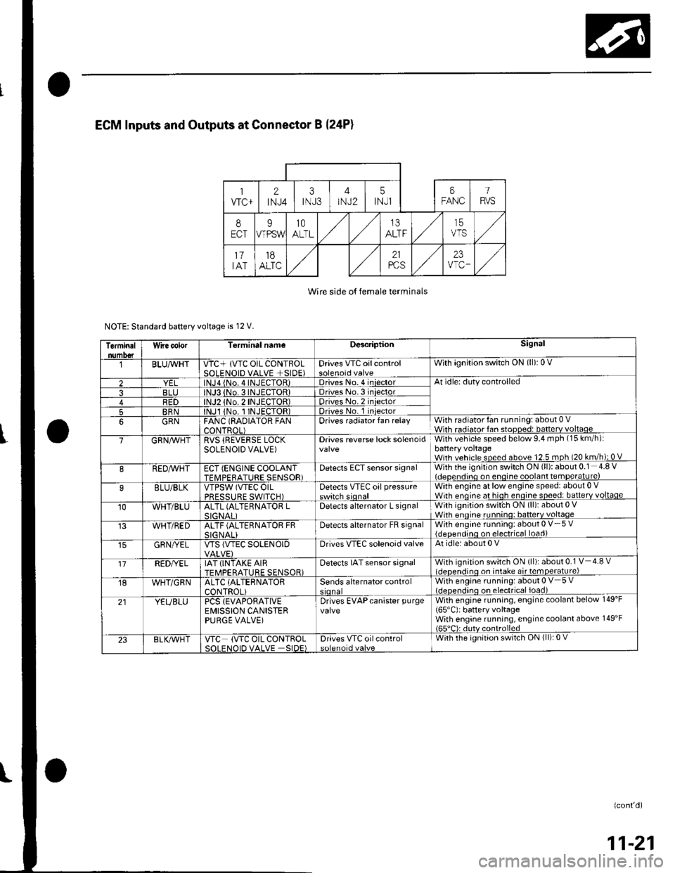
Wire side o{ female terminals
NOTE: Standard baftery voltage is 12 V.
Terminalnumo€tWire color[erminal nameDescriptionSignal
BLUAvHTVTC+ lVTC OIL CONTBOLSOLENOID VALVE +SIDE)Drives VTC oilcontrolWith ignition switch ON (ll): 0 V
2lNJa {No. 4INJECTOR)Driveso. 4 iniectorAt idle: duty controlled
3BLJo.3INJECTORIDriveso.3 iniector4R1)TOR)Driveso.2 iniector
5BRNlNJl 1No. I INJECTOR)Drives No. 1 iniector
6GRNFANC (RAOIATOR FANCONTROL)Drives radiator fan relayWith radiator fan running: about 0 VWith radiator fan stopped: batterv voltaoe
7GRN/vVHTRVS (REVERSE LOCKSOLENOID VALVE)Drives reverse lock solenoidWith vehicle speed below 9.4 mph (15 km/h):battery voltageWith vehicle speed above 12.5 mph (20 km/h): 0 V
8REDAVHTECT (ENGINE COOLANTTFMPFRATURE SENSOR)Detects ECT sensor signalWith the ignition switch ON (ll): about 0.1 4.8 Videoendino on enoine coolant temDerature)
9BLU/BLKVTPSW (VTEC OILPRFSSTIRF SWITCH)Detects VTEc oil pressureswitch sionalWith engine at low engine speed: about 0 .Wirh enoine at hioh enoine soeed: batterv voltaqe
10WHT/BLUALTL (ALTEBNATOR LSIGNAI IDetects alternator L signalWith ignition swit'ch ON (ll): about 0 VWhh enoine runnino: batterv voltaqe
WHT/REDALTF (ALTERNATOR FRSIG NALIDetecls alternator FB signalWith engine running: about 0 V- 5 V{deoendinq on electrical load)
GRN/YELVTS {VTEC SOLENOIDDrives VIEC solenoid valveAt idle: about 0 V
'17REDI/ELIAT (INTAKE AIRTEMPERATURE SENSOR)Detects IAT sensor signalWith ignition switch ON {ll): about 0.1 V 4.8 vl.lcnen.iino on intake air temoerature)
18WHT/GRNALTC (ALTERNATOR
CONTROL)Sends alternator controlWith engine running: about 0 V 5 V(.lcocn.lino on electrical ioad)
21YEUBLUPCS {EVAPORATIVEEMISSION CANISTERPURGE VALVE)
Drives EVAPcanister purgevalveWith engine running, engine coolant below 149'F
165'C): battery voltageWith engine running, engine coolant above 149'F165"C): dutv controlled
23BLK/Vr'HTVTC (VTC OIL CONTROLSOI FNOID VALVE SIDE)Drives VTC oilcontrolWith the ignition switch ON (ll): 0 V
(confd)
11-21
Page 247 of 1139
![HONDA CIVIC 2003 7.G Repair Manual Fuel and Emissions Systems
System Descriptions (contdl
ECM Circuit Diagram {contd)
\
-{ffi]---1t-|
IATSENSOR
-{El------l
ECTSENSOS
T_""",,..
I-BFN/YEL
ft^--l
,","., J t-|:I REVERSEI LocKI soleloto+ HONDA CIVIC 2003 7.G Repair Manual Fuel and Emissions Systems
System Descriptions (contdl
ECM Circuit Diagram {contd)
\
-{ffi]---1t-|
IATSENSOR
-{El------l
ECTSENSOS
T_""",,..
I-BFN/YEL
ft^--l
,","., J t-|:I REVERSEI LocKI soleloto+](/img/13/5744/w960_5744-246.png)
Fuel and Emissions Systems
System Descriptions (cont'dl
ECM Circuit Diagram {cont'd)
\
-{ffi]---1t-|
IATSENSOR
-{El------l
ECTSENSOS
T_""",,..
I-BFN/YEL
ft^--l
,","., J t-|':I REVERSEI LocKI soleloto+ vaLvE
t!j]]
CMPSENSOAA
L-IJUNCTIONI CONNECTOR
-
11-40
Page 320 of 1139
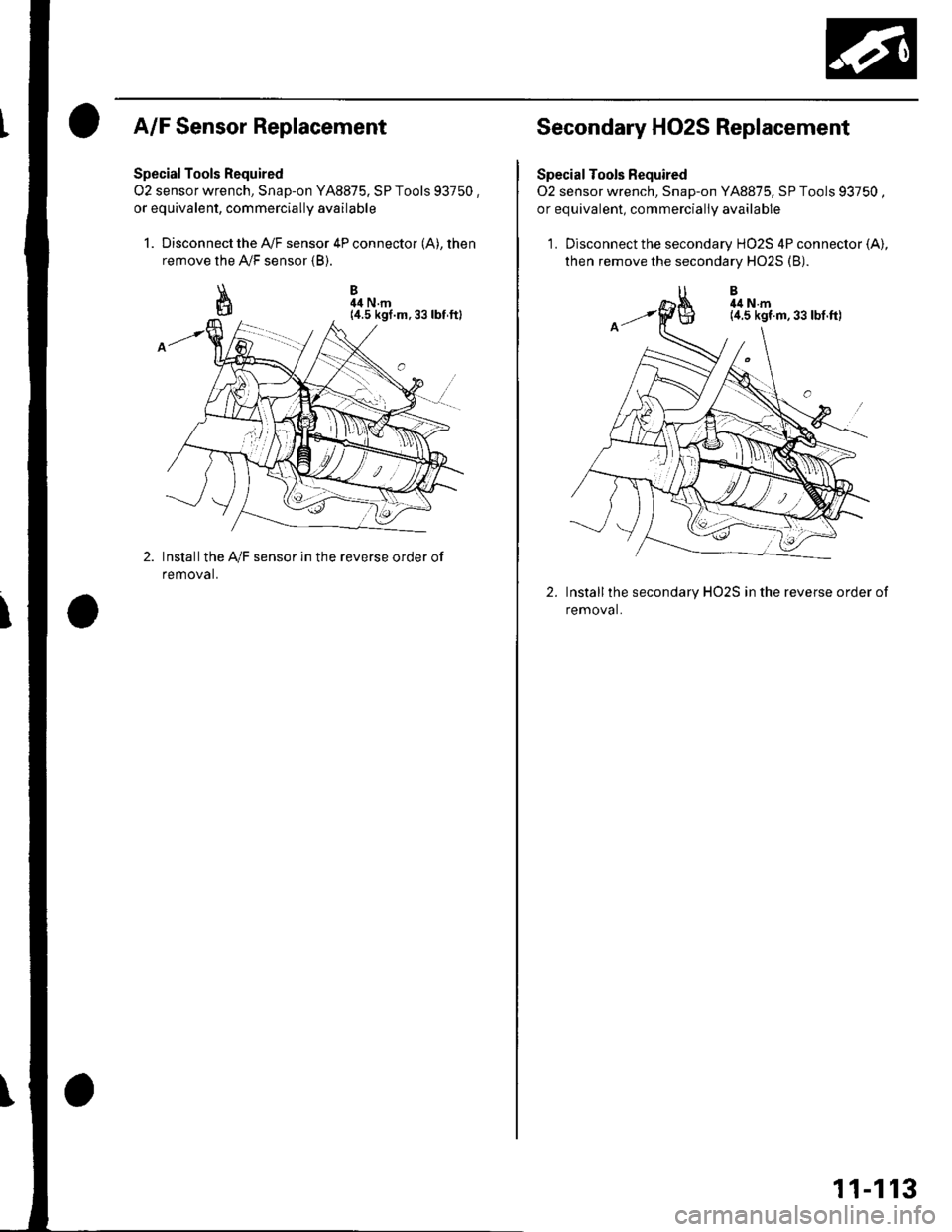
A/F Sensor Replacement
Special Tools Required
O2 sensor wrench, Snap-on YA8875. SP Tools 93750 ,or equivalent, commercially availabre
1. Disconnect the A,/F sensor 4P connector (A), then
remove the A,/F sensor {B).
\I
ffi
B44 N.m
Installthe IVF sensor in the reverse order of
removal.
Secondary HO2S Replacement
Special Tools Fequired
02 sensor wrench, Snap-on YA8875, SP Tools 93750 ,or equivalent, commerciallV available
1. Disconnect the secondary HO2S 4P connector (A),
then remove the secondary H02S (B).
Installthe secondary HO2S in the reverse order of
removal.
2.
11-113
Page 321 of 1139
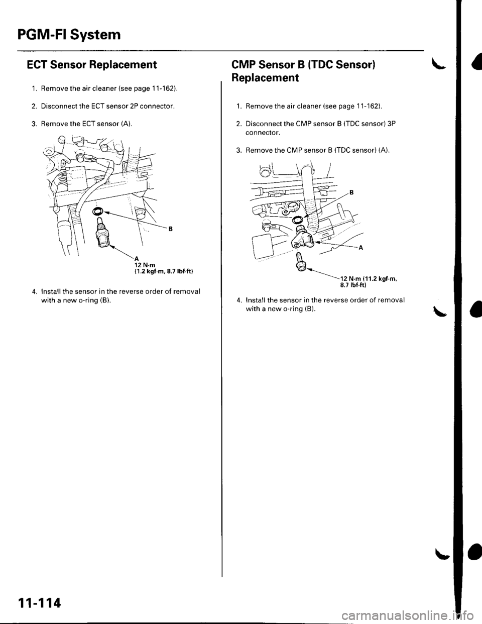
PGM-Fl System
ECT Sensor Replacement
'1. Remove the air cleaner {see page 11-162).
2. Disconnect the ECT sensor 2P connector.
3. Remove the ECT sensor (A).
{1.2 kgt m.8.7 lbt.ft}
reverse order of removallnstallthe sensor in the
with a new o-ring {B).
11-114
CMP Sensor B (TDC Sensorl
't.
2.
Replacement
Remove the air cleaner (see page 11-162).
Disconnect the CN4P sensor B (TDC sensor) 3P
conneclor.
Remove the CMP sensor B (TDC sensor) (A).
----
r, ".- ,',',., *nr...8.7 tbf.ftl
lnstallthe sensor in the reverse order of removal
with a new o-ring {B).
4.
Page 322 of 1139
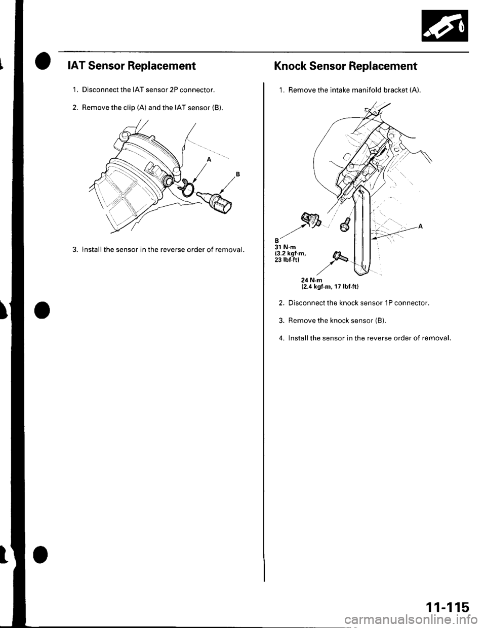
IAT Sensor Replacement
1, Dlsconnect the IAT sensor 2P connector.
2. Remove the clip (A) and the IAT sensor (B).
3. lnstallthe sensor in the reverse order of removal.
Knock Sensor Replacement
1. Remove the intake manifold bracket (A).
2.
3.
4.
24Nm(2.4 kgt.m, 17 lbt.ftl
Disconnect the knock sensor 1P connector.
Remove the knock sensor (B).
Installthe sensor in the reverse order of removal.
11-115
Page 323 of 1139
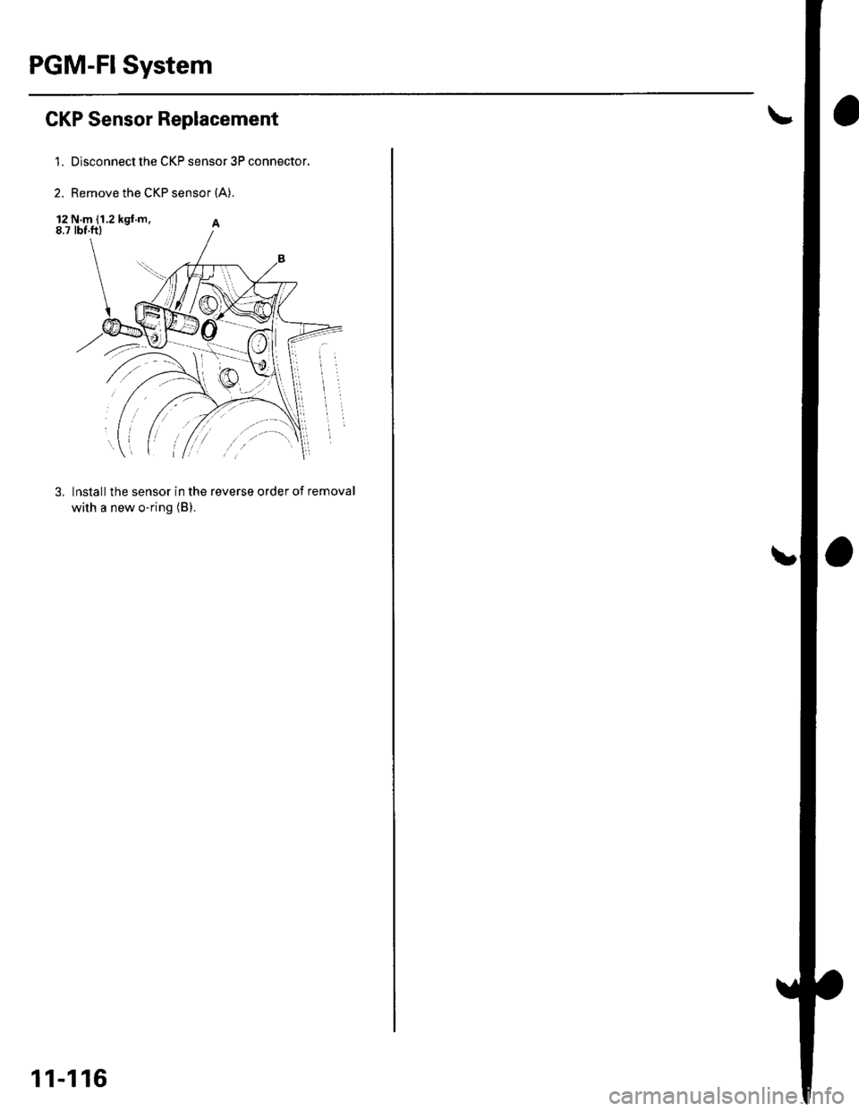
PGM-FI System
GKP Sensor Replacement
1. Disconnect the CKP sensor 3P connector.
2. Remove the CKP sensor {A).
12 N.m (1.2 kgt m.8.7 tbf.ftl
3. lnstall the sensor in the reverse order of removal
with a new o-ring (B).
11-116
Page 334 of 1139
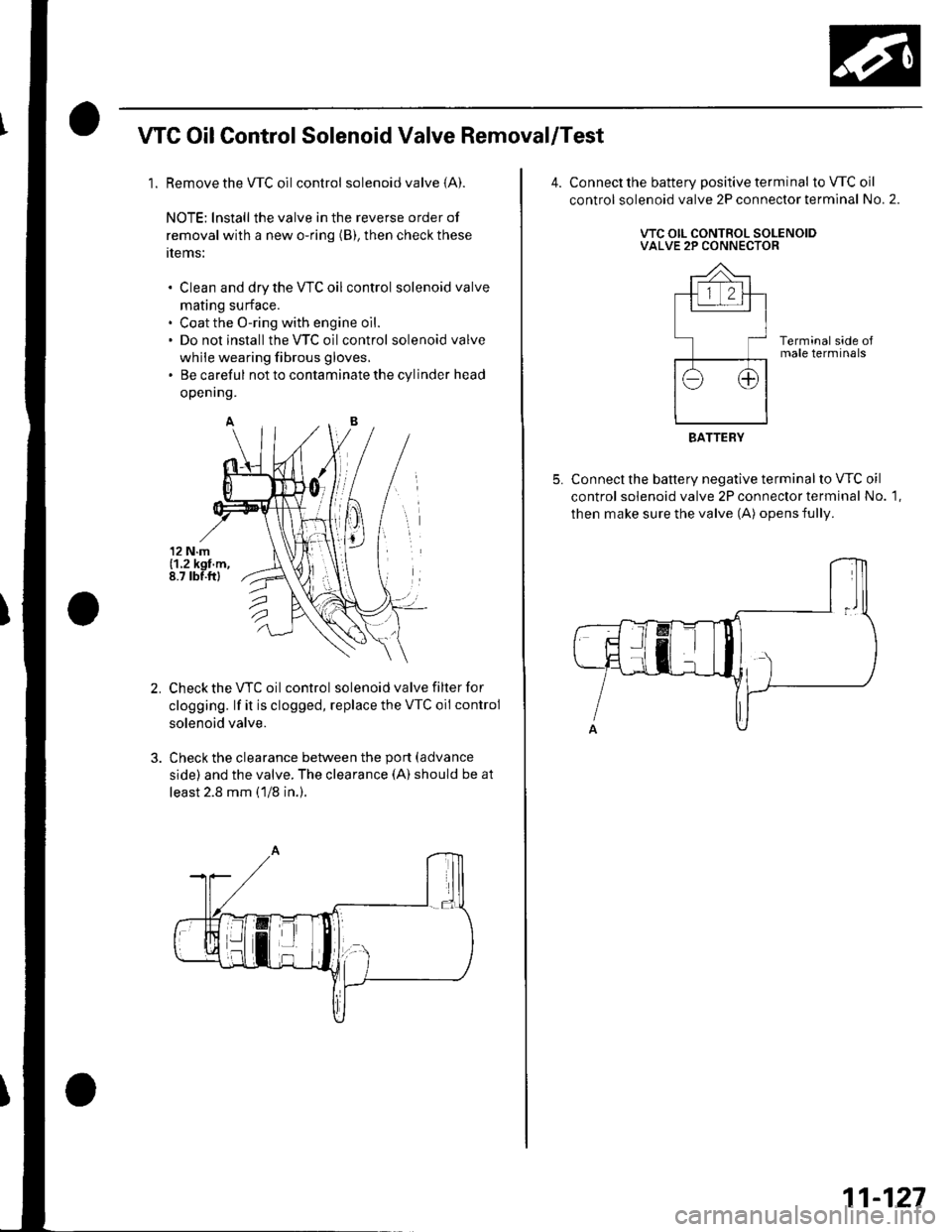
WC OilControl Solenoid Valve Removal/Test
1. Remove the WC oilcontrol solenoid valve (A).
NOTE: lnstall the valve in the reverse order of
removal with a new o-ring (B), then check these
tlems:
Clean and dry the VTC oil control solenoid valve
mating surface.
Coat the O-ring with engine oil.
Do not install the VTC oilcontrol solenoid valve
while wearing fibrous gloves,
Be careful not to contaminate the cylinder head
openrng.
Check the VTC oil control solenoid valve filter for
clogging. lf it is clogged, replace the VTC oil control
solenoid valve.
Check the clearance between the port (advance
side) and the valve. The clearance (A) should be at
least 2.8 mm (1/8 in.).
Connect the battery positive terminal to VTC oil
control solenoid valve 2P connector terminal No. 2.
VTC OIL CONTROL SOLENOIDVALVE 2P CONNECTOR
Terminal side oJmale terminals
Connect the battery negative terminal to VTC oil
control solenoid valve 2P connector terminal No. 1,
then make sure the valve (A) opens fully.
BATTERY
11-127