HEATER UNIT HONDA CIVIC 2003 7.G Workshop Manual
[x] Cancel search | Manufacturer: HONDA, Model Year: 2003, Model line: CIVIC, Model: HONDA CIVIC 2003 7.GPages: 1139, PDF Size: 28.19 MB
Page 710 of 1139
Interior Trim
Carpet Replacement (cont'dl
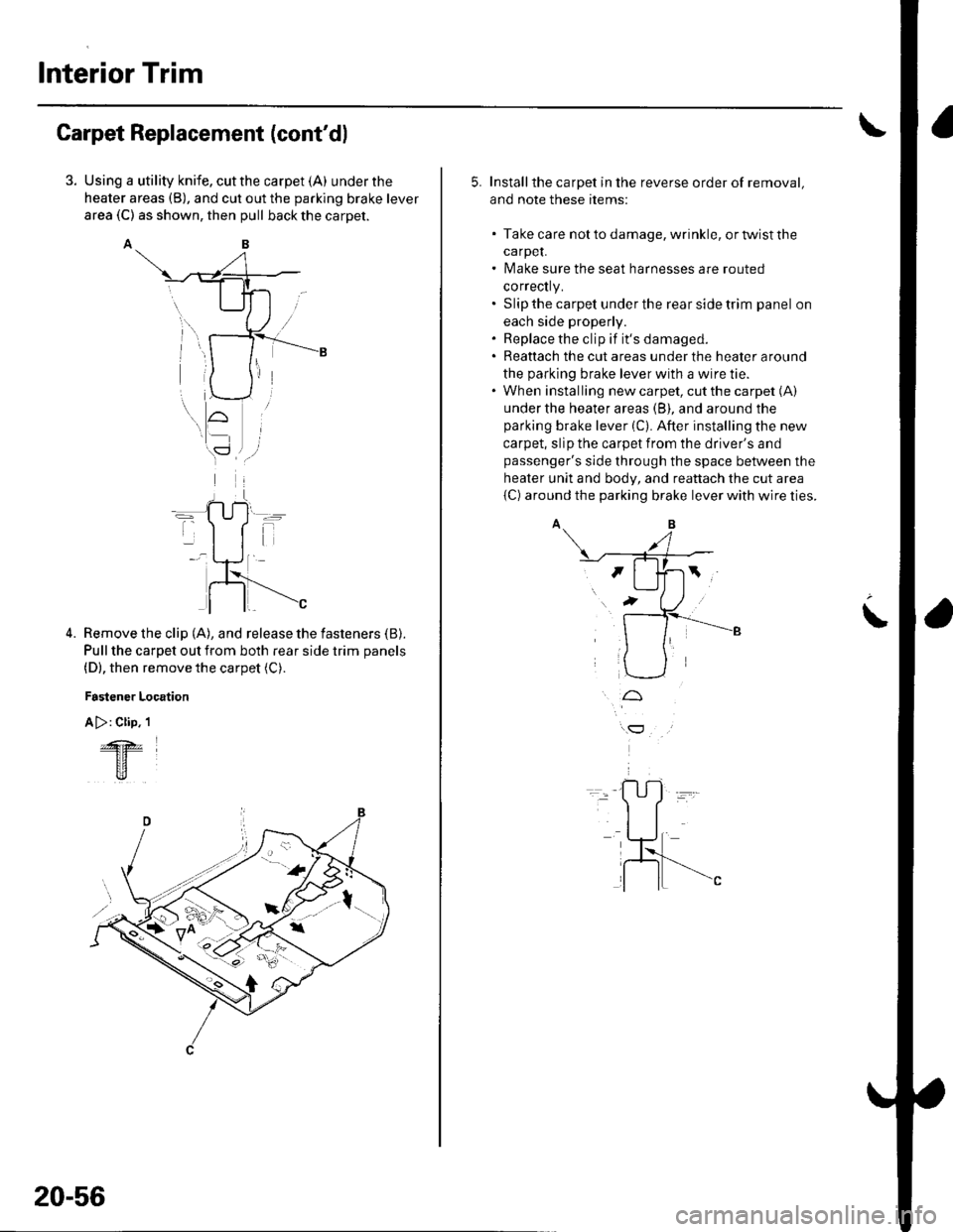
Using a utility knife, cut the carpet (A) under the
heater areas (B), and cut out the parking brake lever
area (C) as shown, then pull back the carpet.
AB
Remove the clip (A), and release the fasteners (B).
Pull the carpet out from both rear side trim panels
(D), then remove the carpet (C).
Fastener Location
A >: Clip. 1
4.
&z
tr
20-56
5. Installthe carpet in the reverse order of removal,
and note these items:
. Take care notto damage, wrinkle, ortwistthe
carpeL. Make sure the seat harnesses are routed
correctly.. Slip the carpet under the rear side trim panel on
each side properly.. Replace the clip if it's damaged.. Reattach the cut areas under the heater around
the parking brake lever with a wire tie.. When installing new carpet, cut the carpet (A)
under the heater areas (B), and around the
parking brake lever (C). After installing the new
carpet, slip the carpet from the driver's and
passenger's side through the space between the
heater unit and body, and reattach the cut area
{C) around the parking brake lever with wire ties.
t
Page 716 of 1139
Dashboard
Dashboard Center Panel Removal/lnstallation
NOTE:. Put on gloves to protect your hands.. When prying with a flat-tip screwdriver, wrap it with
protective tape, and apply protective tape around the
related parts, to prevent damage.. Take care not to scratch the dashboard and related
parts.
1. Make sure you have the anti-theft code for the radio,
the write down the frequencies for the preset
buttons.
Remove these items:
. Driver's dashboard lower cover (see page 20-59)
. Passenger's dashboard lower cover (see page
20-63).. Glove box (see page 20-63).. Shift lever trim {see page 20-61).
From the glove box and driver's dashboard Iower
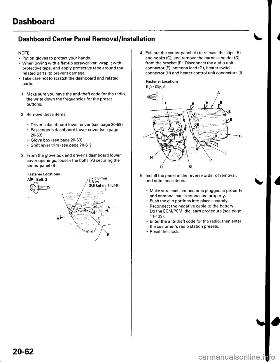
cover openings, loosen the bolts (A) securing the
center panel (B).
2.
Fastener Locations
A): Bolt, 2x 0.8 mm5Nm
;.'
20-62
4. Pull out the center panel (A) to release the clips (B)
and hooks (C), and remove the harness holder (D)
from the bracket (E). Disconnect the audio unit
connector (F), antenna lead (G), heater switch
connector (H) and heater control unit connectors (l).
Fastener Locations
B ): Clip, 8
Installthe panel in the reverse order of removal,
and note these items:
Make sure each connector is plugged in properly,
and antenna lead is connected properly.
Push the clip portions into place securely.
Reconnect the negative cable to the battery.
Do the ECN4/PCt\4 idle learn procedure {see page
1l-139).
Enter the anti-theft code for the radio. then enter
the customer's radio station presets.
Reset the clock.
*4
,F
\
Page 773 of 1139
21-2
z t-'5
z t-o
z t-o
21-8
21-9
21-10
21-11
21-14
z t- to
HVAC (Heating, Ventilation, and Air Gonditioningl
Heating and Air Conditioning
SpecialTools
Comoonent Location lndex ........
A/C Service Tios and
Precautions
A,/C Refrigerant Oil
ReDlacement
General Troubleshooting
lnformation
DTC Troubleshooting Index .......
Symptom Troubleshooting
1ndex..............
System Description .....................
Circuit Diagram
DTC Troubleshooting ..................
Recirculation Control Motor
CircuitTroubleshooting .......... 21-25
Heater Control Power and Ground
Circuits Troubleshooting ........ 21-27
Condenser Fan Circuit
Troubleshooting ...................... 21-28
Radiator and Condenser Fans
Common Circuit
Troubfeshooting ...................... 21-29
Compressor Clutch Circuit
Troubleshooting ...................... 21-30
A,/C Pressure Switch Circuit
Troubleshooting ...................... 21-32
Air Mix Control Motor
Test and Reolacement ............. 21-34
Mode Control Motor
Test and Replacement ............. 21-35
Recirculation Control Motor
Test and Reolacement ............. 21-36
Evaporator Temperature Sensor
Reolacement and Test ............. 21-31
Power Transistor Test ................. 21 -38
Heater Control Panel and
Push Switch Assemblv
Removal and Installation ........ 21-38
Dust and Pollen Filter
Reolacement ..21-39
Blower Unit Removal and
lnstallation ...... 21-39
Blower Unit Comoonents
ReDlacement ............................ 21-41
Evaporator Core
Reolacement ..21-42*Heater Unit/Core
ReDlacement ..21-43
Heater Valve Cable
Adjustment .....21-46
CompressorReplacement .......... 21-47
Comoressor Clutch Check .......... 21-48
Comoressor Clutch Overhaul ..... 21-49
Compressor Thermal Protector
Reo1acement ............................ 21-51
Comoressor Relief Valve
Reolacement ............................ 21-51
Condenser Reolacement ............ 21-52
Refrigerant Recovery .................. 21-53
System Evacuation ...................... 21-54
System CharginS ......................... 21-55
Refrigerant LeakTest .................. 21-56
A,/C Svstem Tests ........................ 21-57
Page 775 of 1139
Heating and Air Gonditioning
Component Location Index
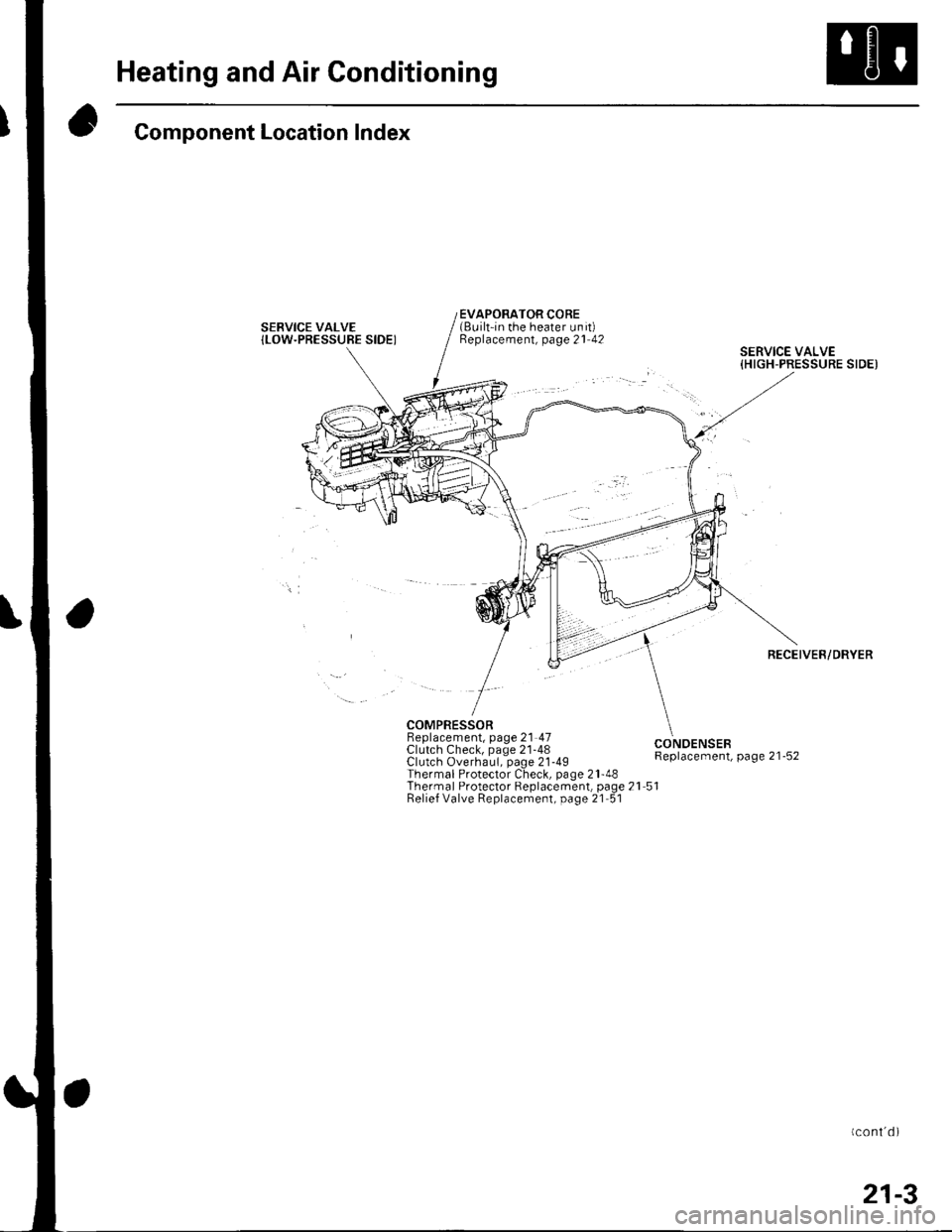
SERVICE VALVE{LOW.PRESSUBE SIDEI
EVAPORATOR CORE(Built-in the heater unit)Beplacement, page 21 42
COMPRESSORBeplacement, page 21 47Clutch Check, page 21-48Clutch Overhaul, page 21-49Thermal Protector Check, page 21-48Thermal Protector Replacement, page 21 51Relief Valve Replacement, page 21 51
SERVICE VALVE{HIGH-PRESSURE SIDEI
RECEIVER/DRYER
CONOENSEBReplacement, page 21-52
Page 777 of 1139
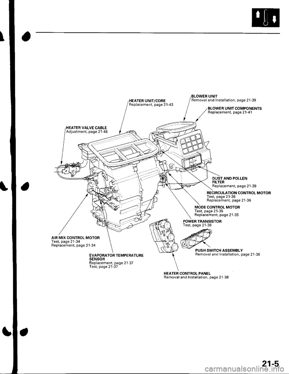
HEATER UNIT/COREBeplacement, page 21-43
BLOWEN UNITRemoval and Installation, page 21-39
HEATER VALVE CABLEAdjustment, page 21-46
BLOWER UNIT COMPONENTSReplacement, page 21-41
DUSTAND POLLENFILTERReplacement, page 21'39
RECIRCULATION CONTROL MOTORTest, page 21-36Replacement, page 21-36
MODE CONTROL MOTORTest, page 21-35Replacement, page 21-35
AIR MIX CONTROL MOTORTest, page 21'34Replacement, page 21'34
POWER TRANSISTORTest, page 21-38
HEATER CONTROL PANELRemovaland Installation, page 21 38
PUSH SWITCH ASSEMBLYRemoval and Installation, page 21'38EVAPORATOR TEMPERATURESENSORReplacement, page 21-37Test, page 21-37
21-5
Page 804 of 1139
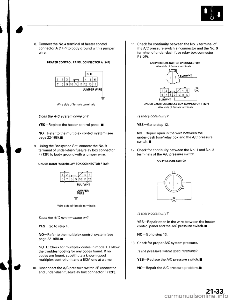
8. Connect the No.4 terminal ofheatercontrol
connector A (14P) to body ground with a jumper
wire,
HEATER CONTROL PANEL CONNECTOR A I14P}
BLU
23456
78Ir0lx1112l3t4
JUMPER WIBE
Wire side of female terminals
Does the A/C system come on?
YES Replace the heater control panel.!
NO Refer to the multiplex control system (see
page 22-168).1
Using the Backprobe Set, connect the No. 9
terminal of under-dash fuse/relay box connector
F (12P) to body ground with a jumper wire.
UNOER.DASH FUSE/RELAY BOX CONNECTOR F {12P}
9.
25
61B g lrotll2
BLU/WHT
JUMPERWIRE
Wire side of female terminals
Does the NC system come on?
YES Go to step 10.
NO- Refer to the multiplex control system (see
page 22-168).1
NOTE: Check for multiplex codes in mode '1. Follow
the troubleshooting {or any codes found. lf no
codes are found, subsititute a known-9ood
multiplex control unit and a ECM one at a time.
Disconnect the Ay'C pressure switch 2P connector
and under-dash fuse/relay box connector F { 12P).
10.
'13.
21-33
11. Check for continuity between the No. 2 terminal of
the A,/C pressure switch 2P connector and the No. 9
terminal of under-dash fuse relav box connector
F t12Pt.
A/C PRESSURE SWITCH 2PCONNECTORWire side of female terminals
UNDER.OASH FUSE/RELAY BOX CONNECTOR F (12P)
Wire side of fenale lerrrinal'
ls there continuity?
YES Go to step 12.
NO Repair open in the wire between the
under-dash fuse/relay box and the A,,/C pressure
switch.I
Check for continuity between the No. 1 and No. 2
terminals of the A,/C pressure switch.
12.
A/C PRESSURE SWITCH
ls there continuity?
YES Repair open in the wire between the heater
control panel and the A,/C pressure switch.l
NO Go to step 13.
check for proper Ay'C system pressure.
ls the pressure within specitications?
YES Replace the AilC pressure switch.l
NO Repair the AilC pressure problem.I
Page 805 of 1139
Heating and Air Conditioning
Air Mix Control Motor Test
1. Disconnect the 5P connector from the air mix
control motor.
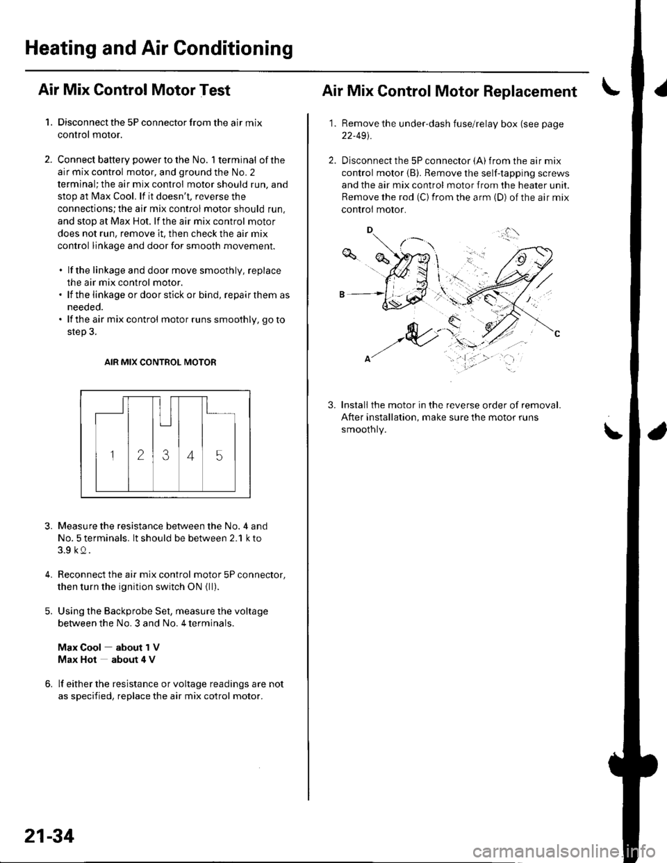
2. Connect battery powertothe No. l terminal ofthe
air mix control motor, and ground the No. 2
terminal; the air mix control motor should run, and
stop at Max Cool. lf it doesn't, reverse the
connections;the air mix control motor should run,
and stop at Max Hot. lf the air mix control motor
does not run, remove it. then check the air mix
control linkage and door for smooth movement.
. lf the linkage and door move smoothly, replace
the air mix control motor.. lf the linkage ordoorstickor bind, repairthem as
needed.. lf the air mix control motor runs smoothly, go to
step 3.
AIR MIX CONTROL MOTOR
3.
4.
Measure the resistance between the No. 4 and
No. 5 terminals. lt should be between 2.1 k to
3.9 kQ.
Reconnect the air mix control motor 5P connector,
then turn the ignition switch ON {ll).
Using the Backprobe Set, measure the voltage
between the No. 3 and No. 4 terminals.
Max Cool about 1V
Max Hot about 4 V
lf either the resistance or voltage readings are not
as specified, replace the air mix cotrol motor.
21-34
Air Mix Control Motor Replacement
1.Remove the under-dash fuse/relay box (see page
22-491.
Disconnect the 5P connector {A) from the air mix
control motor (B). Remove the self-tapping screws
and the air mix control motor from the heater unit.
Remove the rod (C) from the arm (D) of the air mix
controi motor.
Install the motor in the reverse order of removal.
After installation, make sure the motor runs
smoothly.
3.
\'
,.,:l'
Page 806 of 1139
Mode Control Motor Test
Disconnect the 10P connector from the mode
control motor.
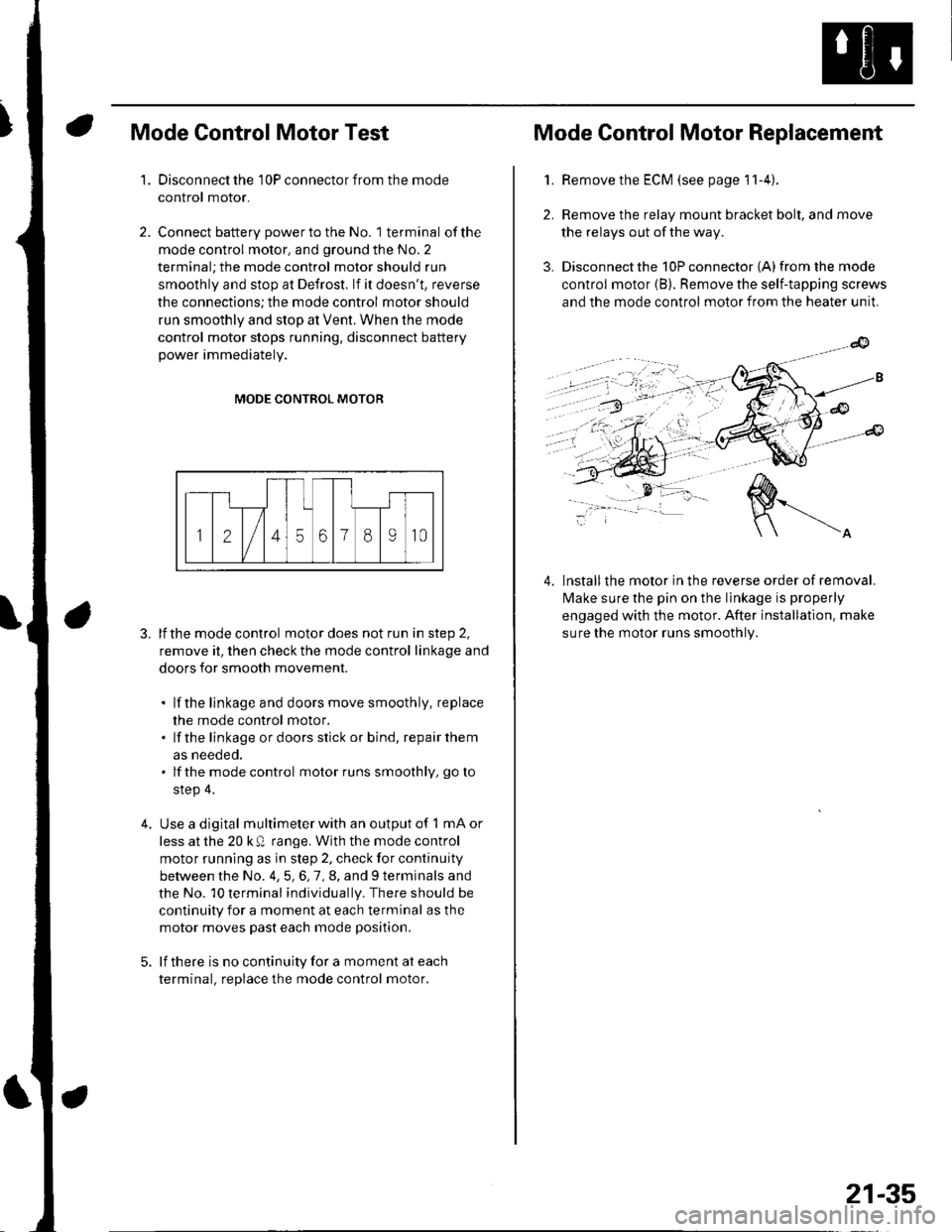
Connect battery power to the No. 1 terminal of the
mode control motor, and ground the No. 2
terminal; the mode control motor should run
smoothly and stop at Defrost. lf it doesn't, reverse
the connections; the mode control motor should
run smoothly and stop at Vent. When the mode
control motor stops running, disconnect battery
power immediately.
'1.
4.
MODE CONTROL MOTOR
3. lfthe mode control motor does not run in step 2,
remove it, then check the mode control linkage and
doors for smooth movement.
. lf the linkage and doors move smoothly. replace
the mode control motor.. lf the linkage ordoorsstick or bind, repairthem
as neeoeo.. lfthe mode control motor runs smoothly, go to
step 4.
Use a digital multimeter with an output of 1 mA or
less at the 20 k Q range. With the mode control
motor running as in step 2, check for continuity
between the No. 4,5,6,7,8, and 9 terminals and
the No. 10 terminal individually. There should be
continuity for a moment at each terminal as the
motor moves past each mode position.
lf there is no continuity for a moment at each
terminal. replace the mode control motor.
Mode Control Motor Replacement
2.
3.
1.Remove the ECM (see page 11-4).
Remove the relay mount bracket bolt, and move
the relays out of the way.
Disconnect the 10P connector {A) from the mode
control motor (B). Remove the self-tapping screws
and the mode control motor from the heater unit.
lnstallthe motor in the reverse order of removal.
lvlake sure the pin on the linkage is properly
engaged with the motor. After installation. make
sure the motor runs smoothly.
4.
21-35
Page 814 of 1139
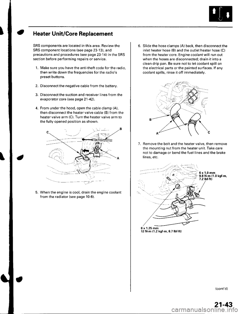
Heater Unit/Core Replacement
SRS components are located in this area. Review the
SRS component locations (see page 23'13), and
precautions and procedures (see page 23-14) in the SRS
section before performing repairs or service.
1. Make sure you have the anti-theft code forthe radio,
then write down the freouencies for the radio's
Dreset buttons.
4.
Disconnect the negative cable from the battery,
Disconnect the suction and receiver lines from the
evaporator core (see page 21-42).
From under the hood, open the cable clamp (A),
then disconnect the heater valve cable (B) from the
heater valve arm (C). Turn the heater valve arm to
the fully opened position as shown
When the engine is cool, drain the engine coolant
from the radiator (see page 10-6).
6. Slide the hose clamps (A) back, the n d isconnect the
inlet heater hose (B) and the outlet heater hose (C)
from the heater core. Engine coolant will run out
when the hoses are disconnected; drain it into a
clean drip pan. Be sure not to let coolant spill on
the electrical parts or the painted surfaces. lf any
coolant spills, rinse it off immediately.
Remove the bolt and the heater valve, then remove
the mounting nut from the heater unit. Take care
not to damage or bend the fuel lines and the brake
lines, etc.
7.
8 x 1.25 mm12 N.m (1.2 kgf.m,8.7lbf.ft)
(cont'd)
21-43
Page 815 of 1139
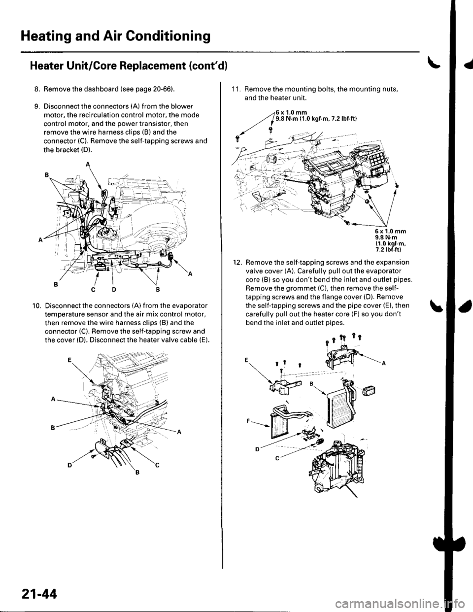
Heating and Air Conditioning
Heater Unit/Core Replacement (cont'd)
8. Remove the dashboard {see page 20-66).
9. Disconnectthe connectors (A) from the blower
motor, the recirculation control motor, the mode
control motor, and the power transistor, then
remove the wire harness clips (B) and the
connector (C). Remove the self-tapping screws and
the bracket (D).
Disconnect the connectors (A) from the evaporator
temperature sensor and the air mix control motor,
then remove the wire harness clips (B) and the
connector (C). Remove the self-tapping screw and
the cover (D). Disconnect the heater valve cable (E).
10,
7t,
21-44
11. Remove the mounting bolts, the mounting nuts,
and the heater unit.
Remove the self-tapping screws and the expansion
valve cover (A). Carefully pull out the evaporator
core (B) so you don't bend the inlet and outlet pipes.
Remove the grommet (C), then remove the self-
tapping screws and the flange cover (D). Bemove
the self-tapping screws and the pipe cover (E), then
carefully pull out the heater core (F) so you don't
bend the inlet and outlet oioes.
@
5x 1.0 mm9.8 N.m11.0 kgl m,7.2 tbf.ftl
12.