LEVER ASS HONDA CIVIC 2003 7.G Workshop Manual
[x] Cancel search | Manufacturer: HONDA, Model Year: 2003, Model line: CIVIC, Model: HONDA CIVIC 2003 7.GPages: 1139, PDF Size: 28.19 MB
Page 28 of 1139
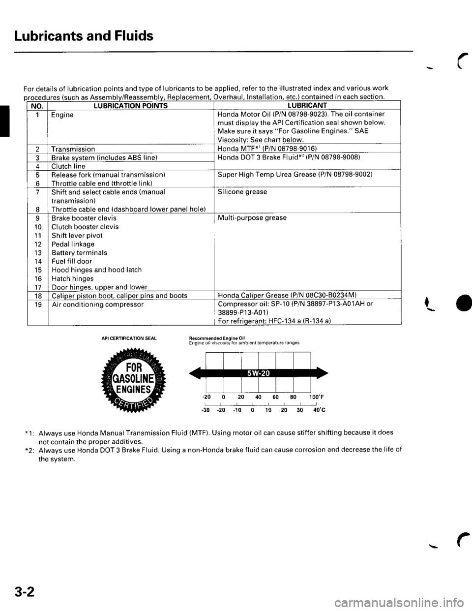
Lubricants and Fluids
For details of lubrication points and type of lubricants to be applied, refer to the illustrated index and various work
ures {such as Assemoverhaul. lnstallation. etc.) contained in each section.
NO.LUBBICATION POINTSLUBBICANT
1E ng ineHonda Motor Oil (P/N 08798-9023). The oil container
must disolav the API Cenification seal shown below.
Make sure it says "For Gasoline Engines." SAE
Viscositv: See chart below.
2TransmissionHonda MTF*' (P/N 08798-9016)
3Brake svstem (includes ABS line)Honda DOT 3 Brake Fluid*'� (P/N 08798-9008)
4Clutch line
5
6
Release fork (manual transmissionl
Throftle cable end (throttle Iink)
Super High Temp Urea Grease {P/N 08798-9002)
7
I
Shift and select cable ends (manual
transmission)
Throttle cable end (dashboard lower panel hole)
Silicone grease
9
10
111'
14
16
17
Brake booster clevis
CIutch booster clevis
Shift lever pivot
Pedal linkage
Battery terminals
Fuel f ill door
Hood hinges and hood latch
Hatch hinges
Door hinoes, uoDer and lower
Multi-purpose grease
18Caliper piston boot, caliper pins and bootsHonda CaliDer Grease (P/N 08C30-80234lvl)
19Air conditioning compressorCompressoroil: SP-10 (P/N 38897-P13-A01AH or
38899-P'13-A01)
For refriqerant; HFC'134 a (R-134 a)
I
Recommond6d Engine OilEngine oilviscosily for amb enttemperalure fanges
-30 -20 -10 0 t0 20
*1:
"2:
Always use Honda Manual Transmission Fluid (MTF). Using motor oii can cause stiffer shifting because it does
not contain the Drooer additives.
Always use Honda DOT 3 Brake Fluid. Using a non-Honda brake fluid can cause corrosion and decrease the life of
the system.
3-2
Page 45 of 1139
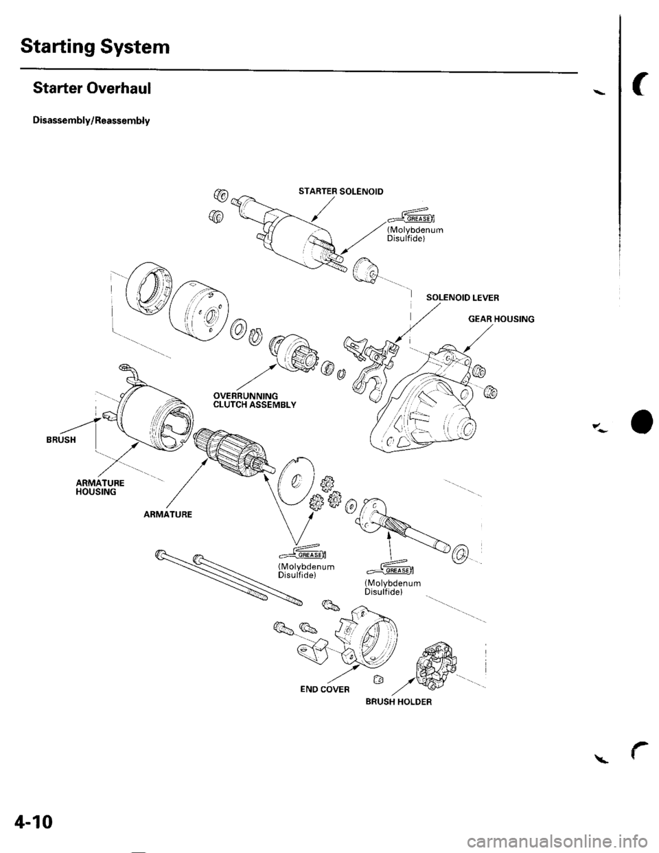
Starting System
Starter Overhaul
Disassembly/Reassembly
f
@
@
,-- ----_2<-
; ,/ 1(-\
rw.h
\:!@a
-
@-A
q -z\hsc6
b-.- ,"OVERRUNNINGCLUTCH ASSEMBLY
G
SOLENOID LEVER
o*"lu*.
V*rN*
\#. A*@
c^)* -#""Jli[X:""
S#o
7:- o
a<-4 t^ fr/ / ffiA-v
9\:-/ ffitr,.. D lWEND COVER t/ '!4/
STARTER SOLENOID
4-10
BRUSH HOLDER
Page 372 of 1139
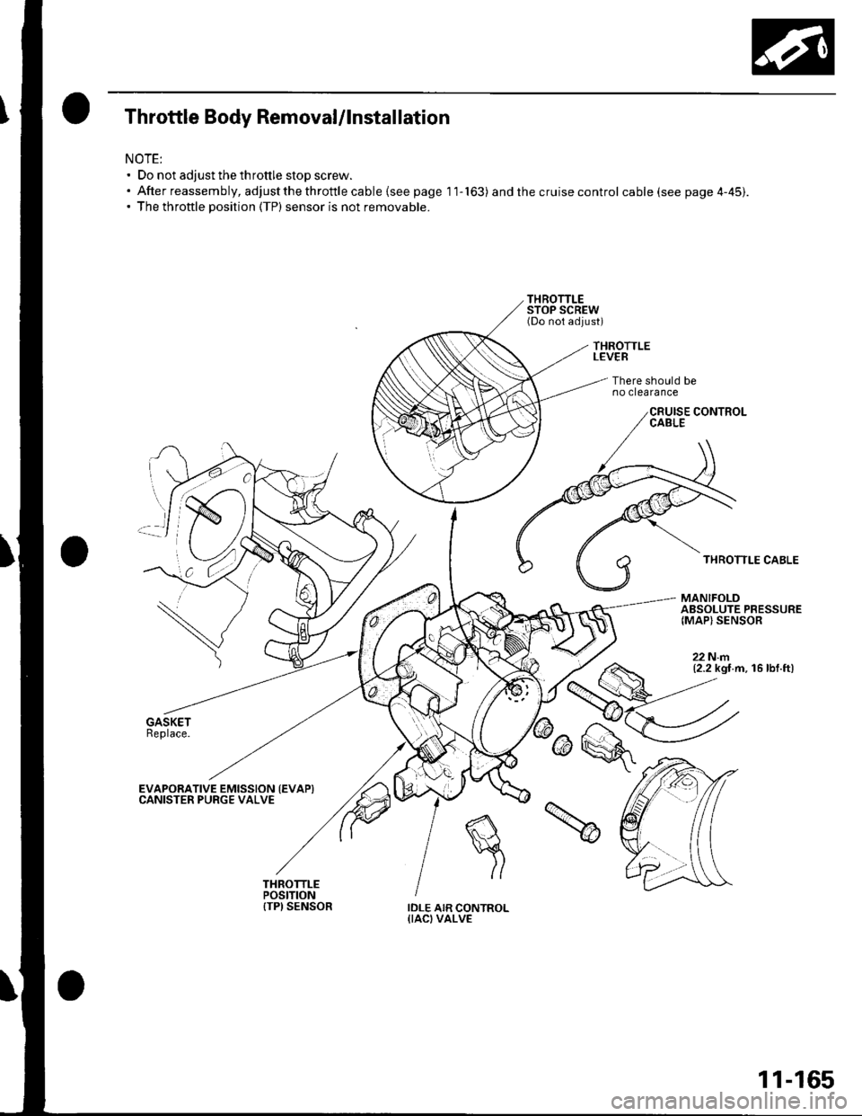
Throttle Body Removal/lnstallation
NOTE:' Do not adjust the throttle stop screw.. Afterreassembly,adjustthethrottlecable{seepagell-163) and the cruise control cable (see page 4-45).. The throttle position (TP) sensor is not removable.
THROTTLELEVER
There should beno clearance
THROTTLE CABLE
MANIFOLDABSOLUTE PRESSURE{MAP} SENSOR
22Nm(2.2 kgt.m, 16 lbf.ft)
EVAPORATIVE EMISSION {EVAPICANISTER PURGE VALVE
IDLE AIR CONTROL{IACI VALVE
11-165
Page 411 of 1139
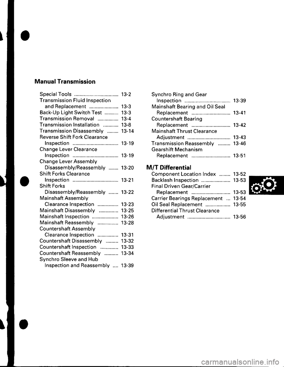
Manual Transmission
SpecialTools
Transmission Fluid Inspection
and Reo1acement ...................-.
Back-Up Light Switch Test ..........
Transmission Removal
Transmission Installation ...........
Transmission Disassemblv ........
Reverse Shift Fork Clearance
lnsoection
Change Lever Clearance
lnsoection
Change Lever Assembly
Disassembly/Reassembly .......
Shift Forks Clearance
Inspection
Shift Forks
Disassembly/Reassembly .......
Mainshaft Assemblv
Clearance Inspection
Mainshaft Disassembly
Mainshaft lnsoection
Mainshaft Reassembly
Countershaft Assemblv
Clearance Inspection
Countershaft Disassembly .........
Countershaft Inspection .............
Countershaft Reassembly ..........
Synchro Sleeve and Hub
Inspection and Reassembly ....
Synchro Ring and Gear
Insoection ....... 13-39
Mainshaft Bearing and Oil Seal
Replacement ........................,... 13-41
Cou ntershaft Bearing
ReDlacement .. 13-42
Mainshaft Thrust Clearance
Adiustment ..... 13-43
Transmission Reassemblv ......... 13-46
Gearshift Mechanism
Replacement ............................ 13-51
M/T Differential
Comoonent Location Index ........ 13-52
Backlash Inspection ..................... 13-53
Final Driven Gear/Carrier
Replacement .. 13-53
Carrier Bearings Replacement ... 13-54
Oil Seal Replacement .................. 13-55
Differential Thrust Clearance
Adiustment ..... 13-56
13-2
| 5-J
tJ-5
13-4
I J-at
13-14
13- 19
13- 19
13-20
13-21
13-22
13-23't3-25
13-26
| 5-2.5
13-31
13-32
13-33
13-34
13-39
Page 425 of 1139
o,. @\
'\b
e
P\B
z-W
-
€:
iq { "
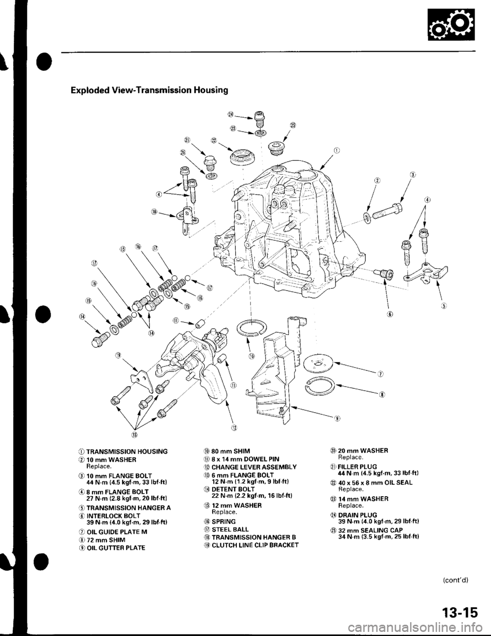
Exploded View-Transmission Housing
@------
tt-P
"=-@
{i) 80 mm SHIM
0 8 x 14 mm DOWEL PIN
[A CHANGE LEVER ASSEMBLY
a0 6 mm FLANGE BOLT12 N m {1.2 kgf.m,9 lbf ft}
O DETENT BOLT22 N.m {2.2 kgf.m, 16lbf.ft)
O 12 mm waSHERReDlace.
(D SPRING
[I STEEL BALL(D TRANSMISSION HANGER B(9 CLUTCH LINE CLIP BRACKET
@
rai\€:/
o
f/
dd
\@
O=-rlF,z
O TRANSMISSION HOUSING
O 10 mm WASHERReplace.
@ 10 mm FLANGE BOLT44 N.m {4.5 kgf.m,33lbf.ft)
O 8 mm FLANGE BOLT27 N.m 12.8 kgf m,20lbl.ft)
.' TRANSMISSION HANGER A
O INTERLOCK BOLT39N m (4.0ksf.m,29lbf.ft)
O OIL GUIOE PLATE M
€.1 72 mm SHIM
.' OIL GUTTEB PLATE
,-1 _\(g/----------__-
"^\
\-/r*---------..-,
@) 20 mm WASHERReplace.
q,] FILLER PLUG44 N m {4.5 kgf.m,33 lbf.ft)
@ 40 x 56 x 8 mm OILSEALReplace.
qO 14 mm WASHERReplace.
q' DRAIN PLUG39 N.m (4.0 kgf.m,29 lbf.ftl
@ 32 mm SEALING CAP34 N m (3.5 kgf.m, 25 lbf.ft)
o
(cont'd)
13-15
Page 426 of 1139
Manual Transmission
Transmission Disassembly (cont'd)
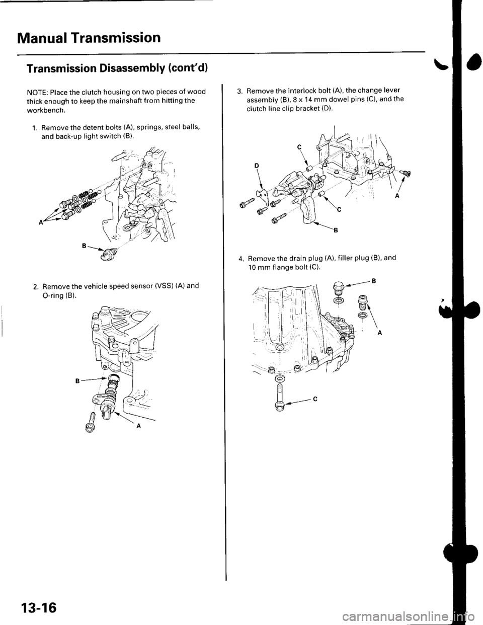
NOTE: Place the clutch housing on two pieces of wood
thick enough to keep the mainshaft from hitting the
workbench.
1. Remove the detent bolts (A), springs, steel balls,
and back-up light switch (B).
Remove the vehicle speed sensor (VSS) (A) and
O-ring (B).
13-16
3, Remove the interlock bolt (A), the change lever
assembly (B), 8 x 14 mm dowel pins (C), andthe
clutch line clip bracket {D).
€
Remove the drain plug (A), filler plug (B), and
10 mm flange bolt (C).
Page 430 of 1139
Manual Transmission
Change Lever Assembly Disassembly/Reassembly
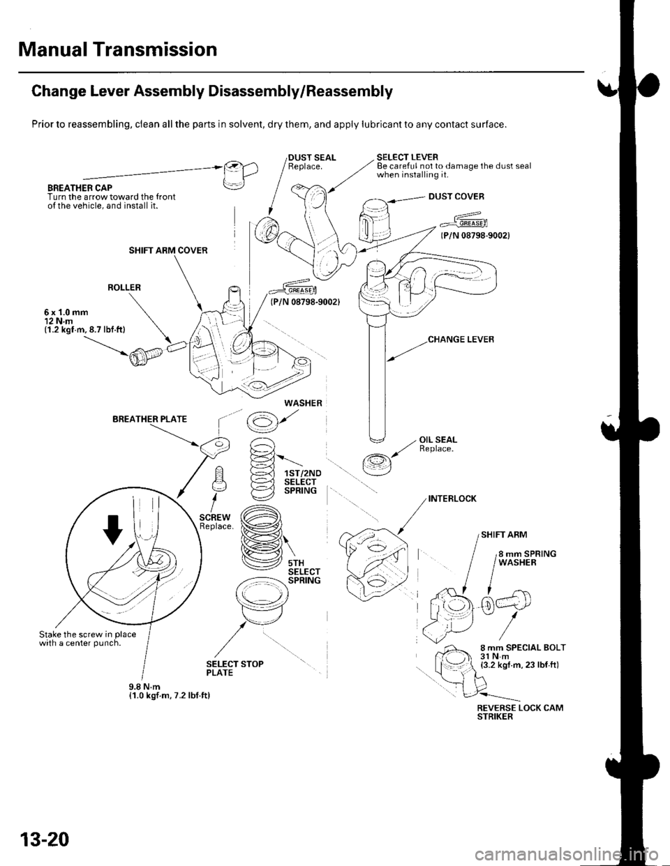
Prior to reassembling, clean all the parts in solvent, dry them, and apply lubricant to any contact surface.
BREATHER CAPTurn the arrow toward the {ronto{ the vehicle, and install it.
SELECT LEVERBe careful not to damage the dust sealwhen installing it.@).1 IlLrl
rrl
I
DUST COVEB
a^^
7 Fr"irr6-rooa
(P/N 08798-9002)
ROLLER
6x1.0mm12 N.m(1.2 kgl.m,8.7 lbf.ft)
'^ E-='-Fl !-d 1sr/2Noq )-=^l sELEcr
i €2 sPntruc
,.* (A)tace. ix�#,,l
H\
lV srxSELECT-z:-=:l-': SPRING
r\
tr7
,/u
/
\op
(g)'
' -, OIL SEAL,/ ReDlace./-r,s
\__/
INTERLOCK
SHIFT ARM
SELECT STOPPLATE
REVERSE LOCK CAMSTRIKER
SHIFT ARM COVER
WASHER
9.8Nm{1.0 kgf.m, 7.2 lbf.ft)
13-20
Page 459 of 1139
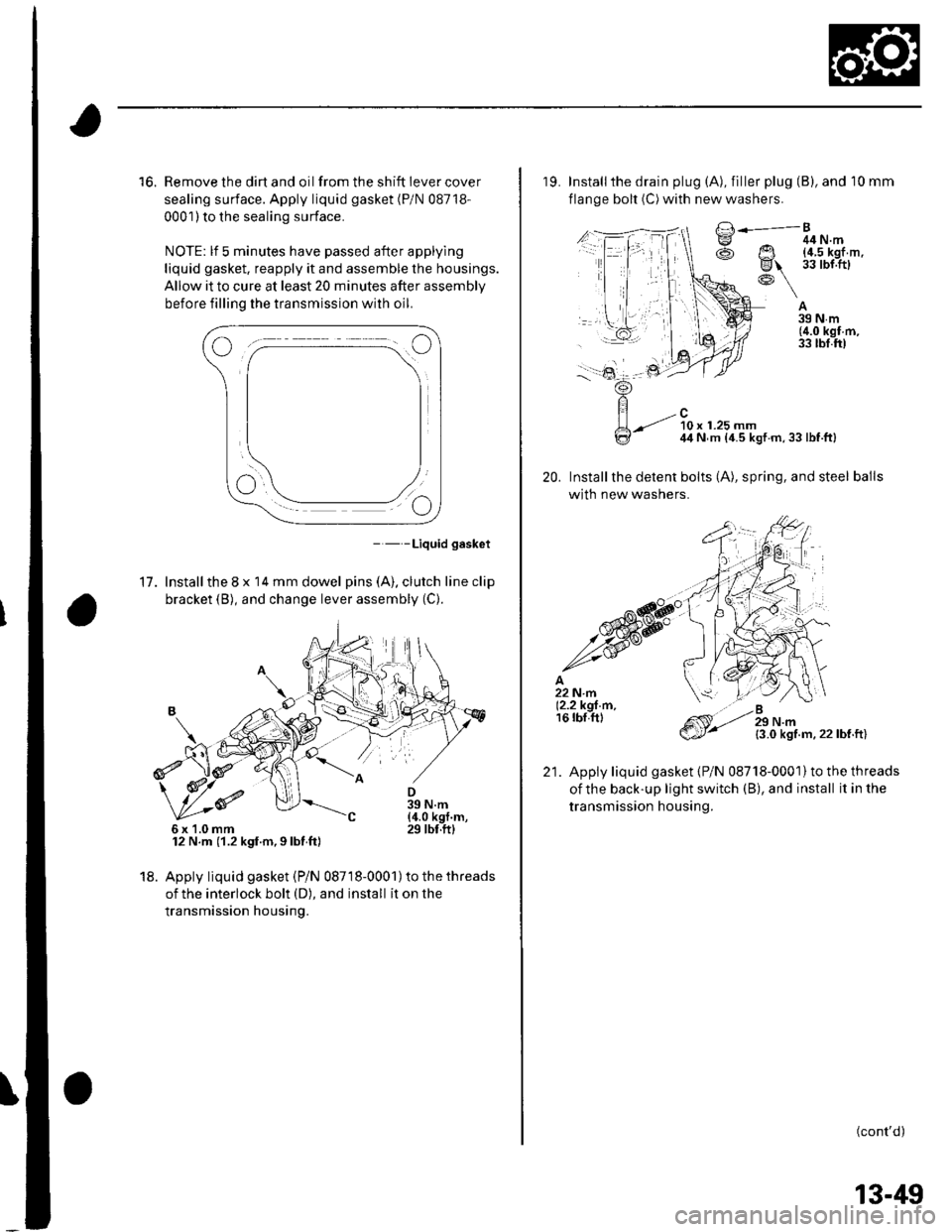
16. Remove the dirt and oil from the shift iever cover
sealing surface. Apply liquid gasket (P/N 08718-
0001) to the sealing surface.
NOTE: lf 5 minutes have passed after applylng
liquid gasket. reapply it and assemble the housings.
Allow it to cure at least 20 minutes after assembly
before filling the transmission with oil.
- - -Liquid gasket
17. Installthe 8 x 14 mm dowel pins (A). clutch line clip
bracket (B), and change lever assembly (C).
12 N.m (1.2 kgf.m,9lbt ft)
18. Apply liquid gasket (Pi N 08718-0001) to the threads
of the interlock bolt (D), and install it on the
transmission housing.
6x1.0mm
19. Installthe drain plug (A), filler plug (B), and 10 mm
flange bolt (C) with new washers.
A39Nm(4.0 kgf m,33 tbl.ft)
20.
/..l-.=,'-Bg ^ 44N.m
@ Ut !?iJl'.'l,''
R\-: \
-.-t ?0, ,.ru ^44 N m {4.5 kgt m,33lbf.ft}
Installthe detent bolts (A), spring, and steel balls
with new washers.
{3.0 kgf.m.22lbf.ft)
Apply liquid gasket {P/N 08718-0001}to the threads
oithe back-up light switch (B), and install it in the
transmission housing.
(cont'd)
21.
13-49
Page 646 of 1139
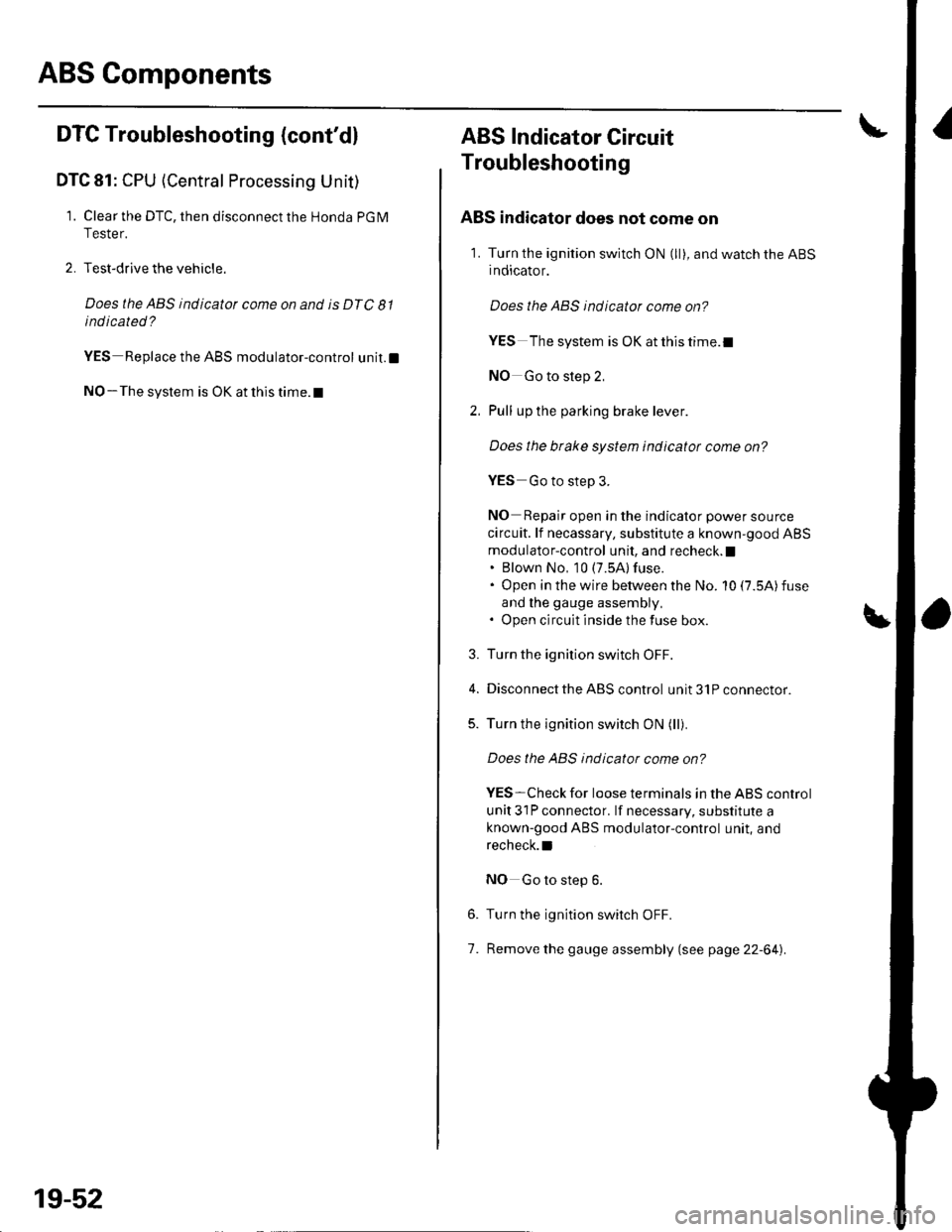
ABS Components
DTC Troubleshooting (cont'd)
DTC 81: CPU (Central Processing Unit)
1. Clear the DTC, then disconnect the Honda PGM
Tester.
2. Test-drive the vehicle.
Does the ABS indicator come on and is DTC 81
indicated ?
YES Replace the ABS modulator-control unit.l
NO-The system is OK at this time. t
19-52
ABS Indicator Gircuit
Troubleshooting
ABS indicator does not come on
1. Turn the ignition switch ON (ll), and watch the ABS
indicator.
Does the ABS indicator come on?
YES The system is OK at this time.I
NO Go to step 2,
Pull up the parking brake lever.
Does the btake system indicator come on?
YES Go to step 3.
NO Repair open in the indicator power source
circuit. lf necassary, substitute a known-good ABS
modulator-control unit, and recheck. I. Blown No, 10 (7.5A) fuse.. Open in the wire between the No. 10 (7.5A)fuse
and lhe gauge assembly,. Open circuit inside the fuse box.
Turn the ignition switch OFF.
Disconnect the ABS control unit 31P connector.
Turn the ignition switch ON (ll).
Does the ABS indicator come on?
YES-Check for loose terminals in the ABS control
unit 31P connector. lf necessary, substitute a
known-good ABS modulator-control unit, and
recheck.l
NO Go to step 6.
Turn the ignition switch OFF.
Remove the gauge assembly (see page 22-64).
3.
5.
6.
7.
Page 654 of 1139
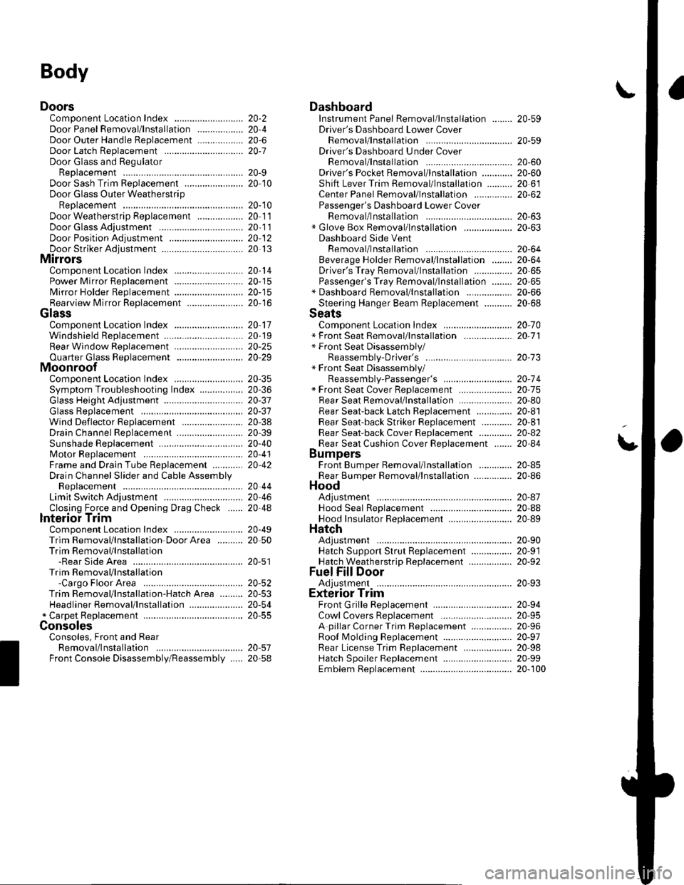
Body
DoorsComponent Location Index ...........Door Panel Removal/lnstallation .....,..........Door Outer Handle ReplacementDoor Latch ReplacementDoor Glass and RegulatorReplacementDoor Sash Trim Replacement .......................
Door Glass Outer WeatherstripReplacement
Door Weatherstrip Beplacement
Door Glass Adjustment .................................Door Position Adjustment .............................Door Striker Adiustment ................................MirrorsComponent Location Index ...........................Power Mirror Replacement ...........................Mirror Holder Replacement ...........................Rearview Mirror Rep1acement ......................
GlassComponent Location Index ...........................Windshield Replacement
Bear Window Rep1acement ...........................
Ouarter Glass Replacement ..........................MoonroofComponent Location Index ...........................Symptom Troubleshooting Index
Glass Height Adjustment ...............................
Glass ReplacementWind Def lector 8ep1acement ........................Drain Channel Rep1acement ..........................Sunshade Replacement .................................Motor ReplacementFrame and Drain Tube Replacement ............Drain Channel Slider and Cable AssemblyReplacementLimit Switch Adjustment ...............................Closino Force and ODenina Draq Check ......lnterioi TrimComponent Location Index ...........................Trim Removal/lnstallation DoorArea ..........Trim Removal/lnstallation-Rear Side AreaTrim Removal/lnstallation-Cargo Floor AreaTrim Removal/lnstallation-Hatch Area .........Headliner Removal/lnstallation* Carpet Rep1acement .......................................ConsolesConsoles, Front and RearRemova l/lnsta llationFront Console Disassembly/Reassembly .....
20-220,420-620-7
20-920 t0
20- 10
20-1120-1120-1220 13
20-1420-1520-1520-16
20 1120-1920-2520-29
20,3520-3620-3720-3120-3820 3920-4020-4120,42
20 4420-4620,44
20-4920 50
20-51
DashboardInstrument Panel Removal/lnstallation ........Driver's Dashboard Lower CoverRemovat InstallationDriver's Dashboard Under CoverRemova t Insta llation
Oriver's Pocket Removal/lnstallation ............Shift Lever Trim Removal/lnstallation ..........Center Panel Removal/lnstallation ...............Passenger's Dashboard Lower CoverRemova l/lnsta llat ionx Glove Box Removal/lnstallationDashboard Side VentRemoval/lnstallation .................................. 20-64Beverage Holder Removal/lnstallation ........ 20-64Driver'sTray Removal/lnstallation ............... 20-65Passenger's Tray Removal/lnstallation ........ 20 65* Dashboard Removal/lnstallation .................. 20-66Steerinq Hanqer Beam Reolacement ........... 20-68Seats "
Component Location Index ........................... 20-10* Front Seat Removal/lnstallation ................... 20-11* Front Seat Disassembly/Reassembly-Driver's .................................. 20-73* Front Seat Disassembly/Reassembly-Passenger's ........................... 20-74* Front Seat Cover Replacement ..................... 2O-75Rear Seat Removal/1nsta11ation ..................... 20-80Rear Seat-back Latch Replacement .............. 20-81Rear Seat-backStriker Replacement ............ 20-81
20-59
20-59
Rear Seat-back Cover Replacement ............. 20-82Rear Seat Cushion Cover Replacement ....... 20.84BumpersFront Bumper Removal/lnstallation .............Rear Bumoer Removal/lnstallation ...............HoodAdjustmentHood Seal ReplacementHood Insulator Rep1acement .........................Hatch
20-6020,6020 6120-62
20-63
20-63
20,8520-86
20-4720,8820,89
20-5220-5320-5420-55
20-5720-58
Adjustment ................... 20-90Hatch Suppon Strut Replacement ................ 20-91Hatch WeatherstriD Reo1acement ................. 20-92
Fuel Fill DoorAdiustment ................... 20-93Exterior TrimFront Grille Replacement ..............Cowl Covers Replac"rn""t .. . .....................A pillar Corner Trim Replacement ................Roof lMolding Replacement ...........................Rear License Trim ReplacementHatch Spoiler 8ep1acement ...........................Emblem Rep1acement .........................
20-9420-9520-9620-9720,9820-9920-100