ac compressor HONDA CIVIC 2003 7.G Workshop Manual
[x] Cancel search | Manufacturer: HONDA, Model Year: 2003, Model line: CIVIC, Model: HONDA CIVIC 2003 7.GPages: 1139, PDF Size: 28.19 MB
Page 22 of 1139
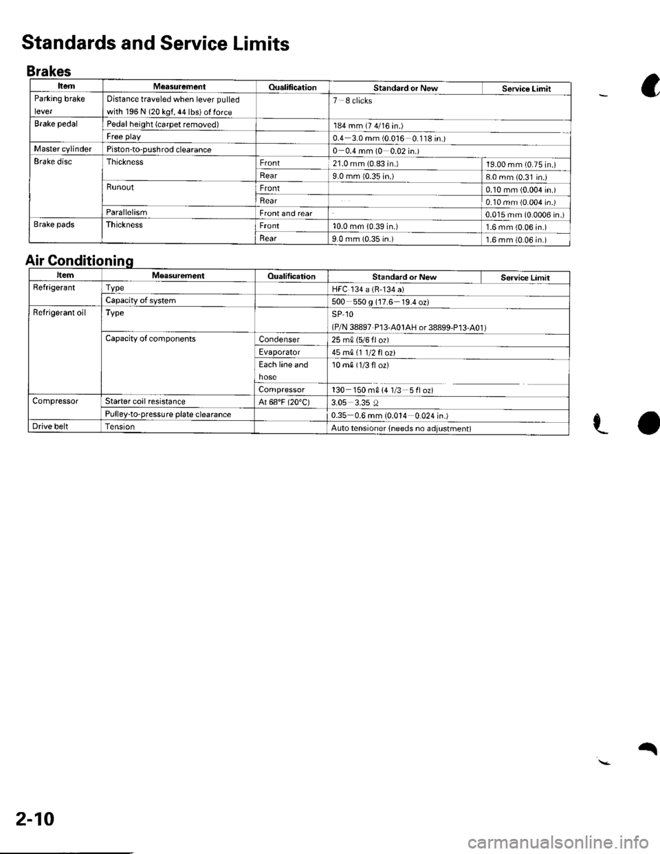
ItemM€asurementOualificationStandard or NewService LimitParking brake
lever
Distance traveled when lever pulled
with 196 N (20 kgf, 44 lbs) ol force
7 8 clicks
Brake pedalPedal height (carpet removed)184 mm (7 4/16 in.)
Free play0.4 3.0 mm (0 016 0 '118 in.)Master cylinderPiston-to-pushrod clearance0 0.4 mm (0 0.02 in.)Erake discThicknessFront21.0 mm (0.83 in.)19.00 mm (0.75 in.)
Rear9.0 mm {0.35 in.)8-0 mm (0.31 in.iRunoutFront0.10 mm (0.004 in.)
Rear0.10 mm (0.004 in.)ParallelismFront and rear0.015 mm (0.0006 in.)Brake padsThicknessFront10.0 mm (0.39 in.)1.6 mm (0.06 in.)
llear9.0 mm {0.35 in.)1.6 mm (0.06 in.)
Standards and Service Limits
Brakes
a
e-o
Air Gonditionin
ItemMoasurementOualilicationStandard or New Service LimitRefrige.antTvpeHFC 134 a (B-134 a)
Capacity of system500 550 g 117.6 19.4 oz)Refrigerant oilTypeSP 1O
(P/N 38897-P13-A01AH or 38899-P13-A01 )Capacity ofcomponentsCondenser25 m0, 15/6 fl ozl
Evaporator45 mA 11 1/2 fl ozt
Each line and
hose
10 m0 (1/3 fl or)
Compressor130 150 m014 1/3 5floz)CompressorStarter coil resistanceAt 68"F (20"C)3.05 3.35 0Pulley-to-pressure plate clearance0.35 0.6 mm (0.014 0.024 in.)Drive beltAuto tensioner lneeds no adjustment)
2-10
q
Page 24 of 1139
cont'
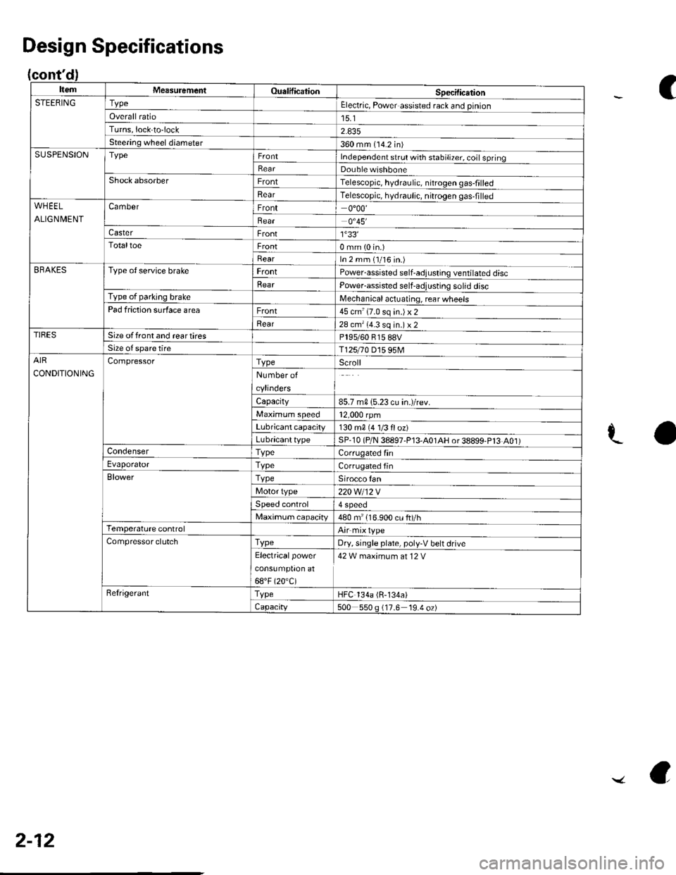
ItemMeasuremeniOualificationSpecilicationSTEERINGTypeElectric, Power assisted rack and pinion
Overall ratio15.1Turns,lock to-lock
Steering wheel diameter360 mm (14.2 in)SUSPENSIONTypeIndependent srrul with stabiliTer. coil springRearDouble wishboneShock absorberFrontTelescopic, hydraulic. nitrogen gas-frlled
RearTelescopic, hydraulic, nitrogen gas,filledWHEEL
ALIGNMENT
CamberFront0"00'
Bear0.45'�
CasterFront1'33'�TotaltoeFront0 mm (0 in.)
RearIn 2 mm (1/16 in.)BRAKESType of service brakeFrontPowerassisted self-adjusling ventilated disc
BearPower-assisted self-adjusting solid discType of parking brakeMechanical actuating, rear wheelsPad friction surface areaFront45 cm'(7.0 sq in.)x2
Rear28 cm'(4.3 sq in.) x 2TIRESSize offront and reartiresPl95/60 815 88VSize o{ spare tireT125r0 D15 95MAIR
CONDITIONING
CompressorTypeScroll
Number of
cylinders
Capacity85.7 m015.23 cu in.)/rev.
Maximum speed12,000 rpm
Lubricant capacity130 m0 {4 1/3 floz)
LubricanttypeSP-10 (P/N 38897'P13-A01AH or38899-P13 A01)CondenserTypeCorrugated finEvaporatorTvpeCorrugated fin
BlowerTypeSirocco fan
Motor type220 Wl12 V
Speed control4 Speeo
Maximum capacity480 m" 116.900 cu ft)/hTemperature controlAirmixtype
Compressor clutchTvpeDry, single plate, poly-V belt drive
Electricalpower
cons!mptron at
68"F (20.C)
42 W maximum at 12 V
RefrigerantTypeHFC 134a (R-134a)
Capacity500 550 g (17.6 19.4 oz)
Design Specifications
C
aL
2-12
../ a
Page 28 of 1139
Lubricants and Fluids
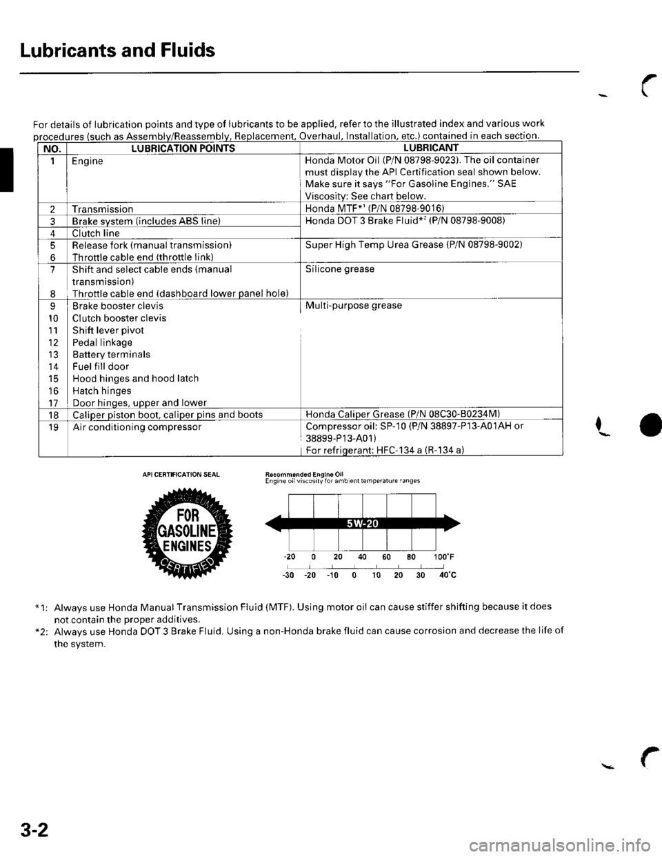
For details of lubrication points and type of lubricants to be applied, refer to the illustrated index and various work
ures {such as Assemoverhaul. lnstallation. etc.) contained in each section.
NO.LUBBICATION POINTSLUBBICANT
1E ng ineHonda Motor Oil (P/N 08798-9023). The oil container
must disolav the API Cenification seal shown below.
Make sure it says "For Gasoline Engines." SAE
Viscositv: See chart below.
2TransmissionHonda MTF*' (P/N 08798-9016)
3Brake svstem (includes ABS line)Honda DOT 3 Brake Fluid*'� (P/N 08798-9008)
4Clutch line
5
6
Release fork (manual transmissionl
Throftle cable end (throttle Iink)
Super High Temp Urea Grease {P/N 08798-9002)
7
I
Shift and select cable ends (manual
transmission)
Throttle cable end (dashboard lower panel hole)
Silicone grease
9
10
111'
14
16
17
Brake booster clevis
CIutch booster clevis
Shift lever pivot
Pedal linkage
Battery terminals
Fuel f ill door
Hood hinges and hood latch
Hatch hinges
Door hinoes, uoDer and lower
Multi-purpose grease
18Caliper piston boot, caliper pins and bootsHonda CaliDer Grease (P/N 08C30-80234lvl)
19Air conditioning compressorCompressoroil: SP-10 (P/N 38897-P13-A01AH or
38899-P'13-A01)
For refriqerant; HFC'134 a (R-134 a)
I
Recommond6d Engine OilEngine oilviscosily for amb enttemperalure fanges
-30 -20 -10 0 t0 20
*1:
"2:
Always use Honda Manual Transmission Fluid (MTF). Using motor oii can cause stiffer shifting because it does
not contain the Drooer additives.
Always use Honda DOT 3 Brake Fluid. Using a non-Honda brake fluid can cause corrosion and decrease the life of
the system.
3-2
Page 88 of 1139
Engine Assembly
Engine Removal (cont'd)
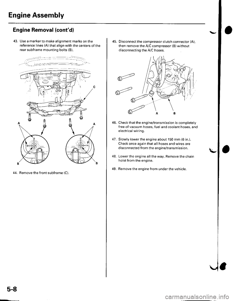
43. Use a marker to make alignment marks on the
reference lines (A) that align with the centers of the
rear subframe mounting bolts (B).
, !:_- _l.= :r -- ---.-','- -
44. Remove the front subframe (C).
5-8
ffi4
ffit'"
45. Disconnect the compressor clutch connector (A),
then remove the Ay'C compressor (B)without
disconnecting the A'./C hoses.
Check that the engine/transmission is completely
free of vacuum hoses, fuel and coolant hoses, and
electrical wiring.
Slowly lower the engine about 150 mm (6 in.).
Check once again that all hoses and wires are
disconnected trom the engine/transmission.
Lower the engine all the way. Remove the chain
hoist from the engine.
Remove the engine from under the vehicle.
46.
47.
48.
49.
Page 89 of 1139
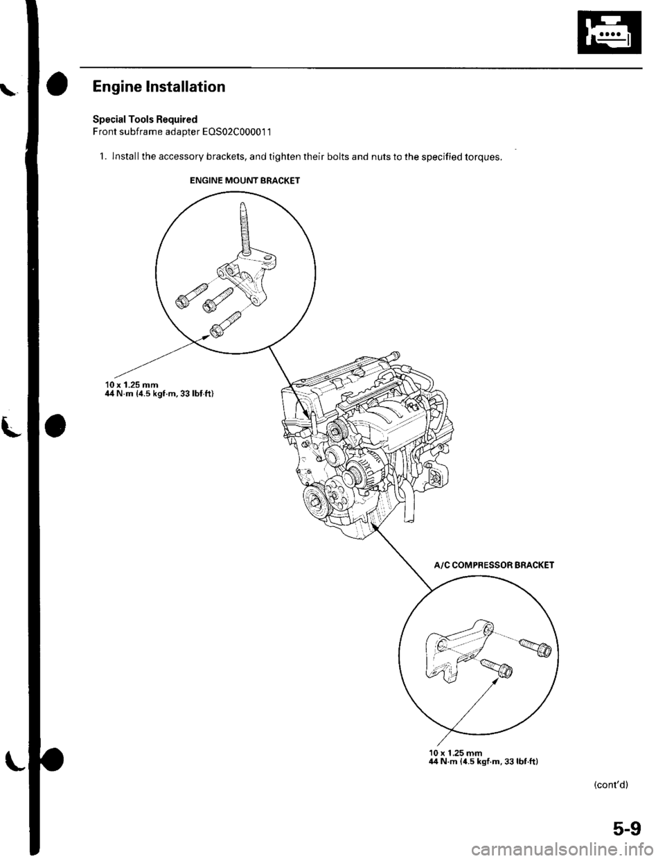
Engine lnstallation
Special Tools Required
Front subframe adapter EOS02C00001 1
1. lnstallthe accessory brackets, and tighten their bolts and nuts to the specified torques.
10 x 1.25 mmil4 N.m {4.5 kgf.m,33lbl.ft)
A/C COMPRESSOR BRACKET
10 x 1 ,25 mm44 N.m {4.5 kgf.m,33lbt.ft)
(cont'dl
ENGINE MOUNT BRACKET
5-9
Page 90 of 1139
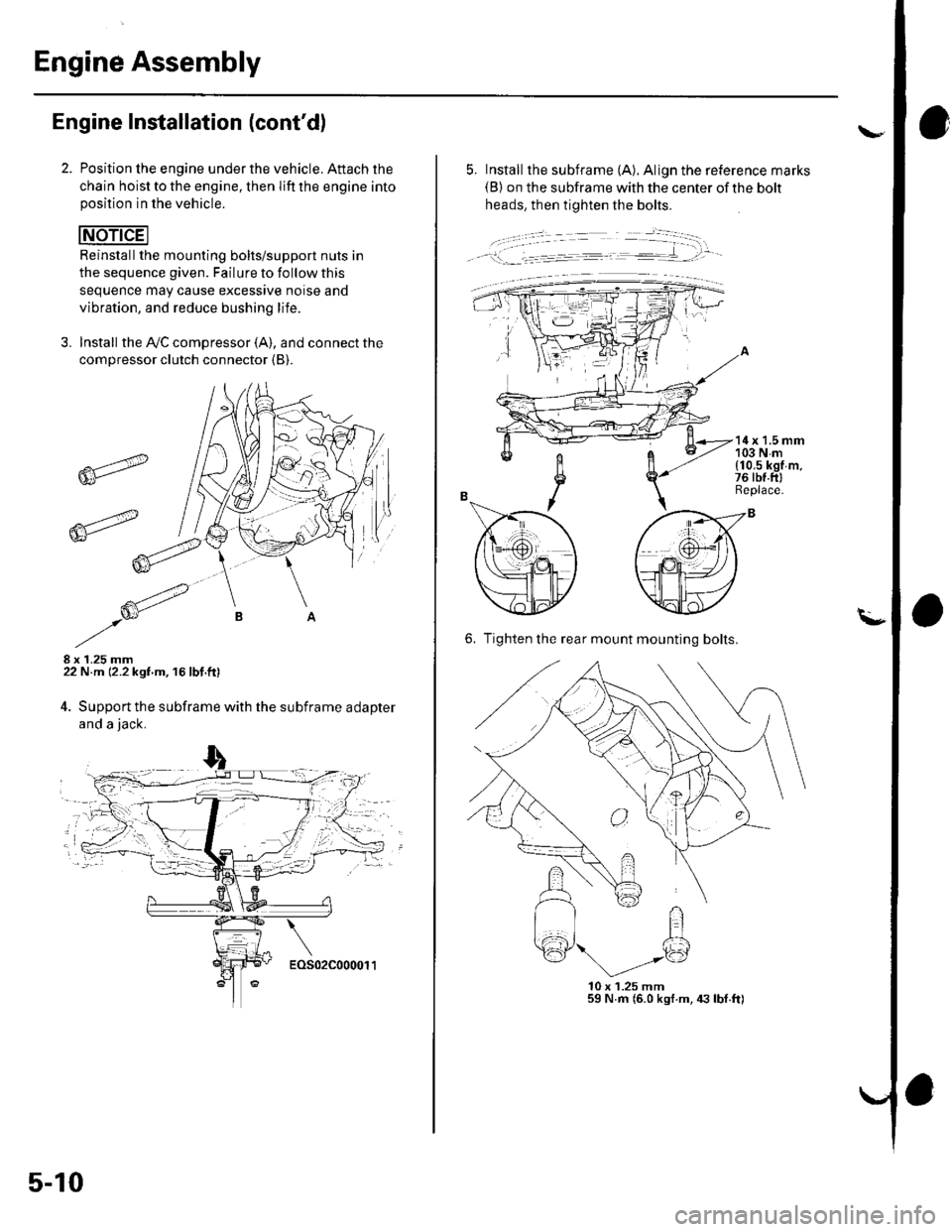
Engine Assembly
Engine Installation (cont'd)
Position lhe engine under the vehicle. Attach the
chain hoist to the engine, then lift the engine intoposition in the vehicle.
Reinstallthe mounting bolts/support nuts in
the sequence given. Failure to follow this
sequence may cause excessive noise and
vibration, and reduce bushing life.
3. Install the A,/C compressor (A), and connect the
compressor clutch connector {B).
8 x 1.25 mm22 N.m 12.2 kgf m. 16 lbf.ft)
4. Support the subframe with the subframe adapter
and a jack.
6r"
6-_-'-
5-10
- - -.'.: - --=---=-- .-€..'tt-
---:-�-�
5. Install the subframe (A). Align the reference marks(B) on the subframe with the center of the bolt
heads, then tighten the bolts.
14x 1.5 mm103Nm{10,5 kgf m.76 rbt.ftlReplace.
6. Tighten the rear mount mounting bolts.
l0x 1.25 mm59 N.m (6.0 kgf.m, 4:] lbI.ft)
FI
Page 97 of 1139
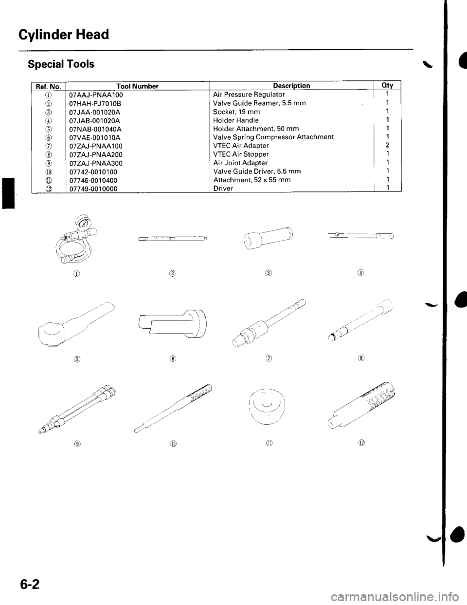
Cylinder Head
aSpecialTools
I
'a- ti-- - -- -i
',..)-)--' -
o
..'.,i2
.<:'':'v''
5'r'
a
/":
-- -'''
't'tY-,l
- 1jr- r--- - l-: ,.
@o
,- '' ,)
,.-/ r--\
a:-t'"
Lq-,
ol?
..#
..a:-"
a,/'/'
@@OD
Ref. No. Tool NumberDescription Oty
O OTAAJ.PNAA'IOO
.D OTHAH-PJ7O1OB
o I oz..rae-oot ozoa
@ 07JAB-0010204
o 07NAB-0010404
G) 07VAE-001010A
OTZAJ.PNAAlOO
E] OTZAJ-PNAA2OO
O I 07ZAJ-PNAA300
tro 07742-0010100
@ 07746-001o4oo(D 07749-0010000
Air Pressure Regulator
Valve Guide Reamer, 5.5 mm
Socket, 19 mm
Holder Handle
Holder Attachment, 50 mm
Valve Spring Compressor Attachment
VTEC Air Adapter
VTEC Alr Stopper
Air Joint Adapter
Valve G uide Driver,5.5 mm
Attachment, 52 x 55 mm
Driver
1
1
1
1
1
1
2
1
1
6-2
Page 102 of 1139
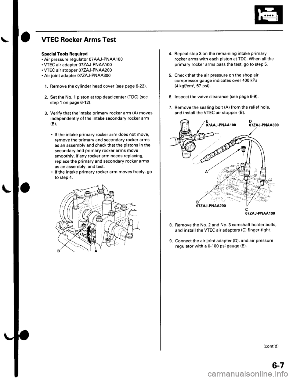
WEC Rocker Arms Test
Special Tools Required. Air pressure regulator 07AAJ-PNAA100. VTEC air adaoter 07ZAJ-PNAA100. WEC air stoDoer 07ZAJ-PNAA200. Air joint adapter 07ZAJ-PNAA300
1. Remove the cylinder head cover (see page 6-22).
2. Set the No. 1 piston at top dead center (TDC) (see
step 1 on page 6-12).
3. Verify that the intake primary rocker arm (A) moves
independently of the intake secondary rocker arm
(B).
. lf the intake primary rockerarm does not move,
remove the primary and secondary rocker arms
as an assembly and check that the pistons in the
secondary and primary rocker arms move
smoothly. lf any rocker arm needs replacing,
replace the primary and secondary rocker arms
as an assemblv, and test.. lfthe intake primary rocker arm moves freely, go
to step 4.
6.
Repeat step 3 on the remaining intake primary
rocker arms with each piston at TDC. When all the
primary rocker arms pass the test, go to step 5.
Check that the air pressure on the shop air
compressor gauge indicates over 400 kPa
(4 kgflcm', 57 psi).
Inspect the valve clearance (see page 6-9).
Remove the sealing bolt (A)from the relief hole,
and install the VTEC air stopper (B).7.
OTAAJ.PNAAlOODOTZAJ-PNAA3OO
Remove the No. 2 and No. 3 camshaft holder bolts,
and installthe VTEC air adapters (C) finger-tight.
Connect the air joint adapter (D), and air pressure
regulator with a 0-100 psi gauge (E).
(cont'd)
OTZAJ.PNAAlOO
6-7
Page 126 of 1139
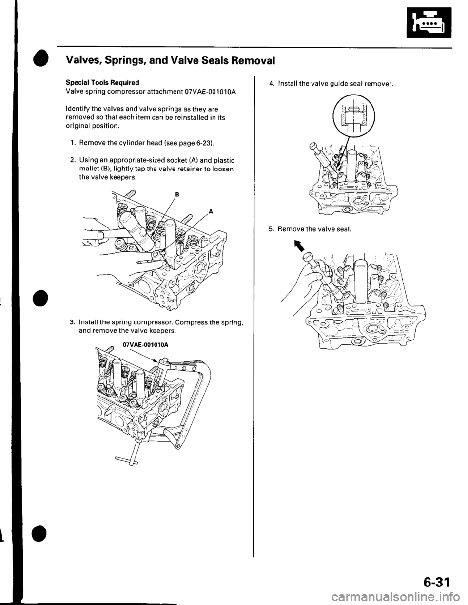
Valves, Springs, and Valve Seals Removal
Special Tools Bequired
Valve spring compressor attachment 07VAE-001010A
ldentify the valves and valve springs as they are
removed so that each item can be reinstalled in its
original position.
1. Remove the cylinder head (see page 6-23).
2. Using an appropriate-sized socket (A) and plastic
mallet {B), lightly tap the valve retainer to loosen
the valve keepers.
Install the spring compressor. Compress the spring,
and remove lhe valve keepers.
4. Installthe valve guide seal remover.
5.the valve seal.Remove
\
6-31
Page 132 of 1139
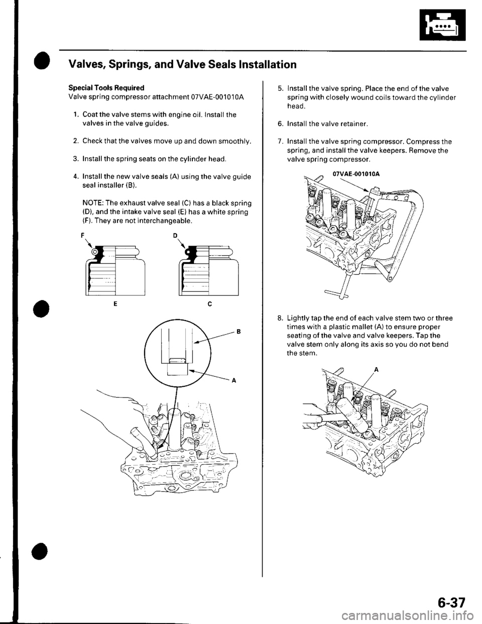
Valves, Springs, and Valve Seals Installation
Special Tools Required
Valve spring compressor attachment 07VAE-00101 0A
1. Coat the valve stems with engine oil. lnstall the
valves in the valve guides.
2. Check that the valves move up and down smoothly.
Installthe spring seats on the cylinder head.
Install the new valve seals (A) using the valve guide
seal installer (B).
NOTE: The exhaust valve seal (C) has a black spring(D), and the intake valve seal (E) has a white spring(F). They are not interchangeable.
6.
lnstallthe valve spring. Place the end ofthe valve
spring with closely wound coils toward the cylinder
n eao.
Install the valve retainer.
Installthe valve spring compressor, Compress the
spring, and install the valve keepers. Remove the
valve spring compressor.
Lightly tap the end of each valve stem two or three
times with a plastic mallet (A) to ensure proper
seating of the valve and valve keepers. Tap the
valve stem only along its axis so you do not bend
the stem.
7.
6-37