plate light HONDA CIVIC 2003 7.G Workshop Manual
[x] Cancel search | Manufacturer: HONDA, Model Year: 2003, Model line: CIVIC, Model: HONDA CIVIC 2003 7.GPages: 1139, PDF Size: 28.19 MB
Page 18 of 1139
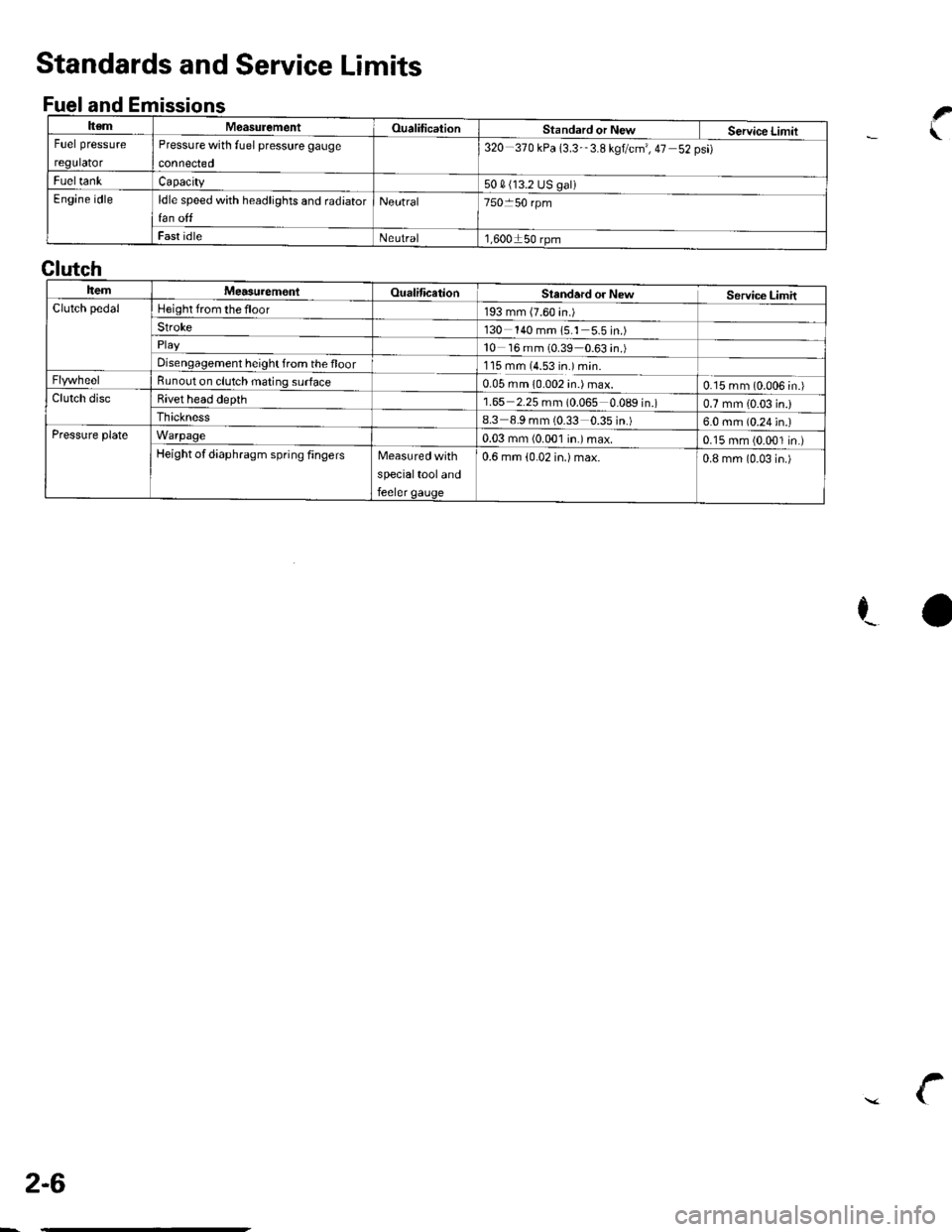
ItemMeasulementOualificationStandard or New Service LimitFuel pressure
regulator
Pressure with fuel pressure gauge
connected
320-370 kPa 13.3-'3.8 kgtcm', 47 52psi)
FueltankCapacity50 4 (13.2 US galiEngine idleldle speed with headlights and radiator
fan off
Neutral750 50 rpm
Fast idleNeutral1,600150 rpm
Standards and Service Limits
Fuel and Emissionsf
.\
ra
Clutch
ItemMea3urem€nlOualificationSlandard or NewService LimitClutch pedalHeight from the floor193 mm (7.60 in.)Stroke130 140 mm 15.1 5.5in.)
10 16 mm (0.39 0.63 in.)Disengagement height from the floor1'15 mm (4.53 in.) min.Bunout on clutch mating surface0.05 mm 10.002 in.) max.0.15 mm (0.006 in.)Clutch discBivet head depth1.65 2.25 mm (0.065 0.089 in.)0.7 mm {0.03 in.)Ihickness8.3 8.9 mm (0.33 0.35 in.)6.0 mm (0.24 in.)Pressure plateWarpage0.03 mm (0.001 in.)max.0.15 mm (0.001 in.)Height of diaphragm spring fingersMeasured with
specialtool and
feeler gauge
0.6 mm (0.02 in.) max.0.8 mm (0-03 in.)
2-6
\
Page 25 of 1139
t
v
2-13
o
o
a
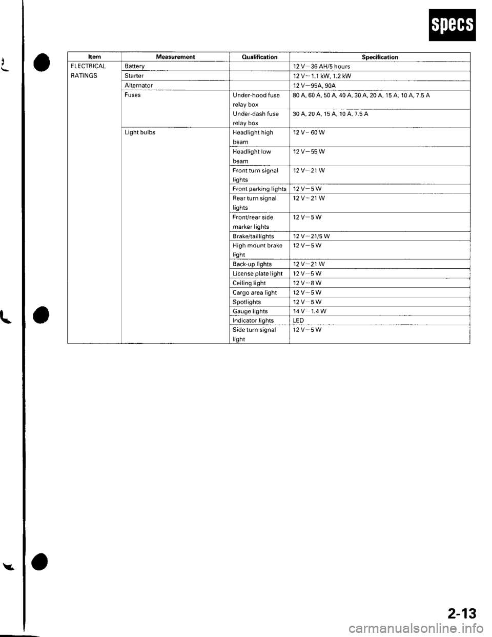
ItemMeasurementOualilicationSpecitication
ELECTRICAL
RATINGS
Battery12V 36 AH/5 hours
Sta rter12 V-.1.1 kW, 1.2 kW
Alternator12V 95A,90A
FusesUnder-hood fuse80 A, 60 A, 50 A, 40 A, 30 A, 20 A, 15 A, 10 A, 7.5 A
Under'dash Iuse30 4,20 a, 15 A, 10 A,7.5 A
Light bulbsHeadlight high
beam
'12 v.' 60 w
Headlight low
beam
12V 55W
Frontturn signal
liqhts
12V 21W
Front parlinq lights12V 5W
Bear turn signal
lights
12V " 21W
FronVrear side
marker lights
12V 5W
Brale/taillighls12V 21/5W
High moLrnt brake
light
12V 5W
Back up lights12V 21W
License plate light12V 5W
Ceiling light'12 v'.8 w
Cargo area light12V 5W
Spotlights12V 5W
Gauge lights
Indicator lightsLED
Side turn signal
light
12V 5W
Page 424 of 1139
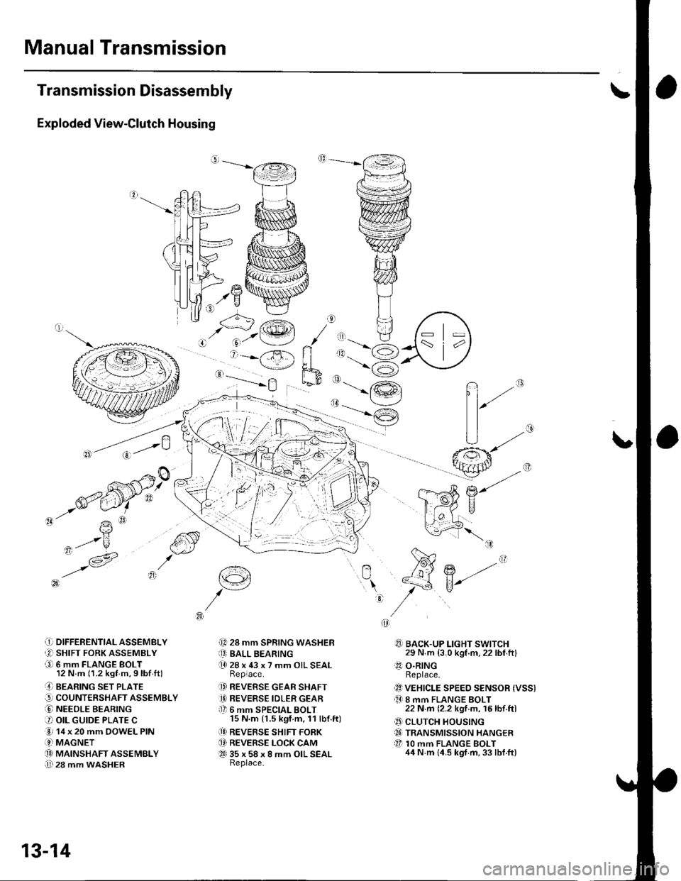
Manual Transmission
Transmission Disassembly
Exploded View-Clutch Housing
,.Y
-'- R
,ot/u
,t- v -1A' i6 t3l
\?
q'/V^
.!) DIFFERENTTAL ASSEMBLY
r2l SHIFT FORK ASSEMBLY
a9l 6 mm FLANGE BOLT12 N.m (1.2 kgf m,9lbf ftl
..4] BEARING sET PLATE
G, COUNTERSHAFT ASSEMBLY
O NEEDLE BEARING
3 OIL GUIDE PLATE C
e 14 x 20 mm DOWEL PIN
.9-i MAGNETi.!! MAINSHAFT ASSEMBLY
U 28 mm WASHER
t€4
i[, 28 mm SPRING WASHERiO BALL BEARING(l 28 x 43 x 7 mm OIL SEALReplace.
.D REVERSE GEAR SHAFT
1' REVERSE IDLER GEARf lr 6 mm SPECIAL BOLT15 N.m (1.5 kgt.m, 11 lbf.ft)
(!I REVERSE SHIFT FORK
.4' REVERSE LOCK CAMQ-t 35 x 58 x 8 mm OIL SEALReplace.
n""
?]] BACK-UP LIGHT SWITCH29 N m (3.0 kgf.m,22 lbf ftl.?1 O.RINGReplace.
1!) VEHICLE SPEEo sENsoR (Vss).O 8 mm FLANGE BOLT22 N.m (2.2 kgf m, 16lbf.ftl
.' CLUTCH HOUSINGiI6) TRANSMISSION HANGER
tl 10 mm FLANGE BOLT44 N.m {4.5 kgt.m,33 lbf.ft}
:
r'<__J'.@t / ,, tl
' j=-X ri ,1.-6
'-==-Yh,_-9
13-14
Page 587 of 1139
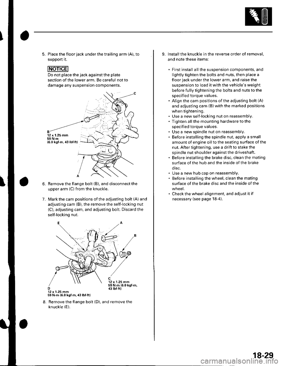
5. Place the floor jack under the trailing arm {A), to
support it.
Do not place the jack against the plate
section of the lower arm, Be careful not to
damage any suspension components.
12 x 1.25 mm59 N.m{6.0 ksf.m.43lbf.ft)
1.
Remove the flange bolt (B), and disconnect the
upper arm {C) from the knuckle.
Mark the cam positions of the adjusting bolt (A) and
adjusting cam (B), the remove the self-locking nut
{C}, adjusting cam, and adjusting bolt. Discard the
self-locking nut.
12 x 1.25 mm59Nm(6.0kgf.m,43 tbI.ftl12 x 1.25 mm59 N.m {6.0 kgf m,43lbl.ft)
8. Remove the flange bolt (D), and remove the
knuckle {E).
9. Installthe knuckle in the reverse order of removal,
and note these items:
. First install all the suspension components, and
lightly tighten the bolts and nuls, then place a
floor jack under the lower a rm, and raise the
suspension to load it with the vehicle's weight
before fully tightening the bolts and nuts to the
specified torque values.. Align the cam positions of the adjusting bolt (A)
and adjusting cam (B) with the marked positions
when tightening.. Use a new self-locking nut on reassembly.. Tighten allthe mounting hardware to the
specified torque values.. Use a new spindle nut on reassembly.. Before installing the spindle nut, apply a small
amount of engine oil to the seating surface of the
nut. After tightening, use a drift to stake the
spindle nut shoulder against the driveshaft.. Before installing the brake disc, clean the mating
surface of the hub and the inside of the brake
drsc.. Use a new hub cap on reassembly.. Before installing the wheel, clean the mating
surface of the brake disc and the inside of the
wheel.. Check the wheel alignment, and adjust it if
necessary {see page 18-4).
18-29
Page 739 of 1139
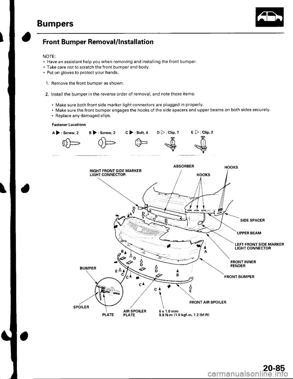
Bumpers
Front Bumper RemovaUlnstallation
NOTE:. Have an assistant help you when removing and installing the front bumper.. Take care not to scratch the front bumper and body.. Put on gloves to protect your hands.
'L Remove the front bumper as shown.
2. Installthe bumper in the reverse order of removal, and note these items:
. Make sure both front side marker light connectors are plugged in properly.
. Make sure the front bumper engages the hooks of the side spacers and upper beams on both sides securely.
. Replace any damaged clips.
Fastener Locations
A),Screw, 2
{D[]
>:Bolt.4 D>:Clip,7 E >:Clip,2
f'h-64k/- *S =$t
B >: Screw,2 C
ABSORBER
SIDE SPACER
UPPER BEAM
LEFT FRONT SIDE MARKERLIGHT CONNECTOR
BUMPER
FRONT INNERFENDER
FEONT BUMPER
AEClI
6x9.8
FRONT AIR SPOILER
AIR SPOILERPLATE1.0 mmN.m (1.0 kgt.m,7.2 lbf.ft)
'*D ;e3
e
ti-\
SPOILER
PLATE
20-85
Page 831 of 1139
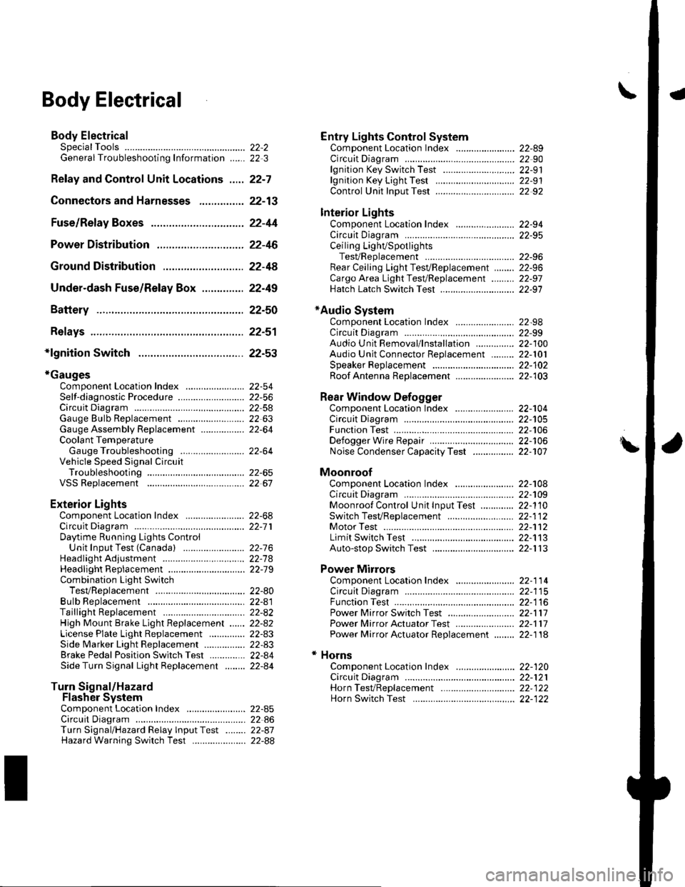
\Body Electrical
Body ElectricalSpecialToolsGeneral Troubleshooting tntorrnaiion.'......
Relay and Control Unit Locations .....
Connectors and Harnesses
Fuse/Relay Boxes ...............................
Power Distribution .............................
Ground Distribution ...........................
Under-dash Fuse/Relay Box ..............
Battery ..............
Relays ................
*lgnition Switch ..............
*Gauges
Component Location Index .......................Self-diagnostic Procedure ..........................Circuit DiagramGauge Bulb Replacement ..........................Gauge Assembly ReplacementCoolant Temperature
Gauge Troubleshooting .... ....................Vehicle Speed Signal CircuitTroubleshootingVSS Replacement
Exterior LightsComponent Location Index .......................Circuit DiagramDaytime Running Lights ControiUnit Input Test (Canada) ........................Headlight Ad,ustment .................. .. .....Headlighr Replacement ..............................Combination Light SwitchTest/ReplacementBulb ReplacementTaillight Replacement ..........................High Mount Brake Light Replacement ......License Plate Light Replacement ..............Side Marker Light Replacement ................Brake Pedal Position Switch Test ..............Side Turn Signal Light Replacement ........
Turn Signal/HazardFlasher SystemComponent Location Index .......................Circuit DiagramTurn Signal/Hazard Relay lnputTest ........Hazard Warning Switch Test
22,3
22-7
22-13
22-44
22-46
22-4A
22-49
22-50
22-51
22-53
22-5422-5622-5422 6322-64
22-64
22-6522 61
22-6822--71
22-7 622-7422-79
22-AO22-4122-8222-4222-4322-4322-4422-84
22-8�522 A622-8722-88
22-10422-105
22-10622-107
Entry Lights control systemComponent Location Index ....................... 22-89Circuit Diagram ......... 22 90lgnition Key Switch Test .....................,...... 22-9'llgnition Key Light Test ............................... 22-91Control Unit Input Test ..........,.................... 22 92
Interior LightsComponent Location Index ....................... 22-94Circuit Diagram ......... 22-95Ceiling LighVSpotlightsTesVReplacement ................................... 22-96Rear Ceiling Light TesVReplacem ent ........ 22-96Cargo Area Light Test/Replacem ent ......... 22-97Hatch Latch Switch Test ..,..,....................... 22-97
*Audio SystemComponent Location Index ....................... 22-98Circuit Diagram ......... 22,99Audio Unit Removal/lnstallation ............... 22-1OOAudio Unit Connector Replacement ......... 22-101Speaker Replacement ................................ 22-102Roof Antenna Rep1acement ....................-.. 22-103
Rear Window DefoggerComponent Location Index ...........Circuit Diasram .. ....... .. ..... ....... ...:::::.::.::.Function TestDefogger Wire Repair .................................Noise Condenser CapacityTest ................
MoonroofComponent Location Index ....................... 22-1OBCircuit Diagram ......... 22-109Moonroof Control Unit Input Test ............. 22-'l10Switch TesVReplacement ........,.....,........... 22-1 12Motor Test ................. 22-112Limit Swilch Test ...... 22-'l'13Auto-stop Switch Test ................................ 22-1 13
Power MirrorsComponent Location Index ....................... 22-114Circuit Diagram ......... 22-115Function Test ............. 22-116Power Mirror Switch Test .......................... 22-ll7Power Mirror Actuator Test ....................... 22-117Power Mirror Actuator Replacement ........ 22-11A
* HornsComponent Location Index ....................... 22-120Circuit Diagram ......... 22-121Horn TesVReplacement ...........................-. 22-122Horn Switch Test .,.... 22-122
\
Page 870 of 1139
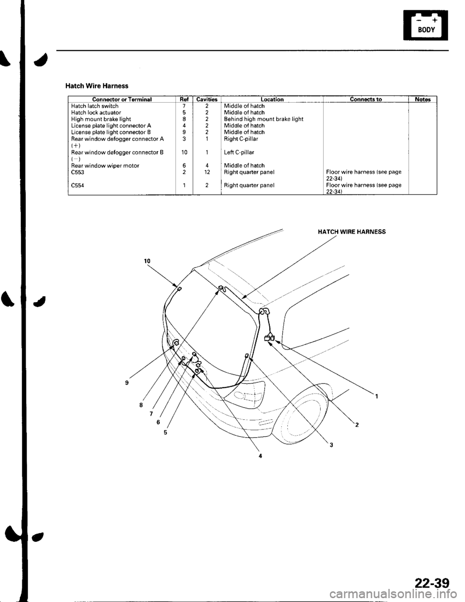
Hatch Wire Harness
Connector or TorminalCavitiesLocationConnects toNotesHatch latch switchHatch lock actuatorHigh mount brake lightLicense plate light connector ALicense plate light connector BRear window de{ogger connector A
Bear window detogger connector B()Bear window wiper moto.c553
c554
7
8
I3
10
62
l
222221
1
412
2
Middle o{ hatchMiddle of hatchBehind high mount brake lightMiddle of hatchMiddle of hatchRight C-pillar
Left C-pillar
Middle of hatchRight quaner panel
Right quaner panel
Floor wire harness (see page22-341Floor wire harness (see page)2-34\
22-39
Page 877 of 1139
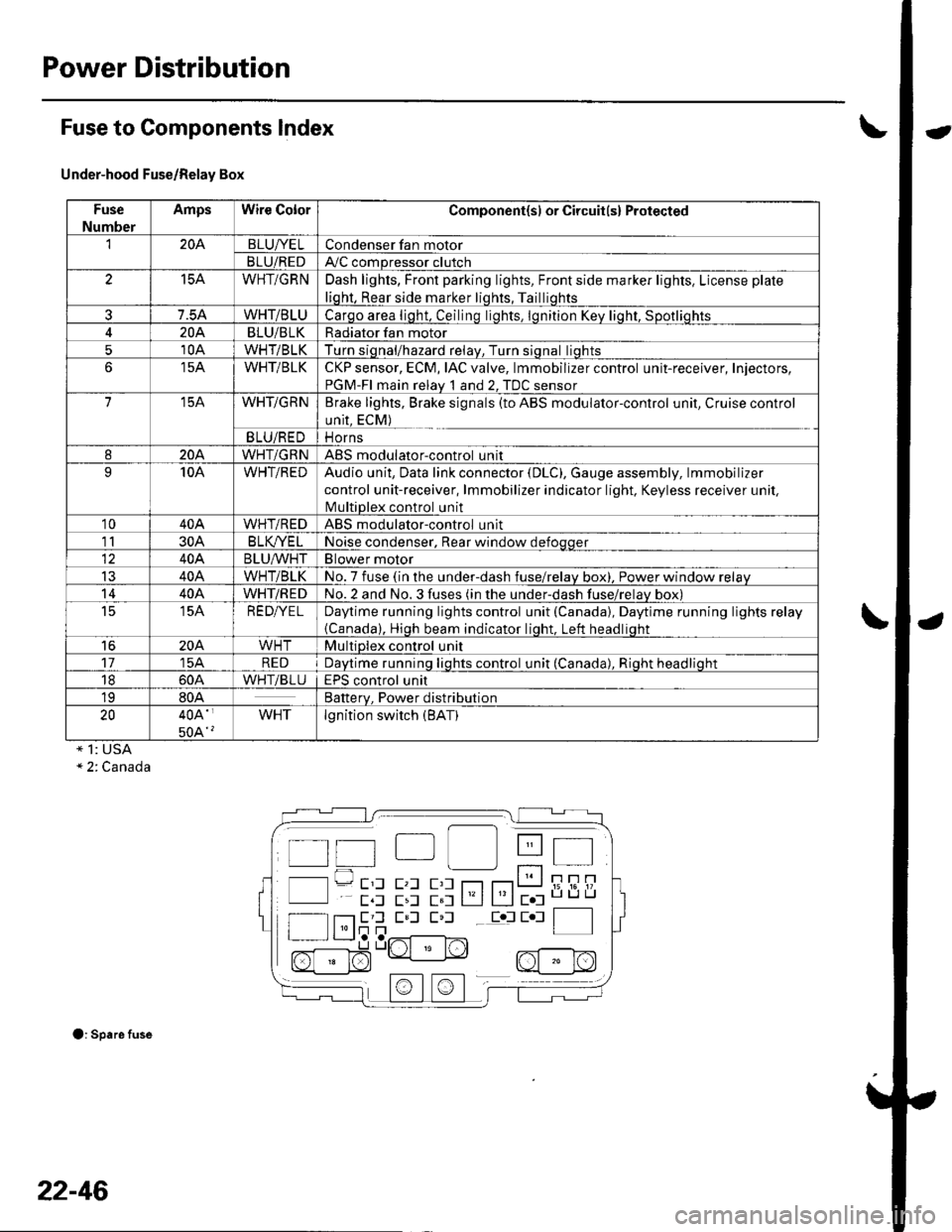
Power Distribution
Fuse to Components lndex
Under-hood Fuse/Relay Box
Fuse
Number
AmpsWire ColorComponent(sl or Circuit(s) Protected
'I204BLUI/ELCondenser fan motor
BLU/REDAy'C compressor clutch
15AWHT/GRNDash lights, Front parking lights, Front side marker lights, License plate
liqht, Rear side marker liqhts, Tailliqhts
7.5AWHT/BLUCarqo area liqht, Ceilinq liqhts. lqnition Kev liqht. Sootliohts
204BLU/BLKRadiator fan motor
510AWHT/BLKTurn siqnal/hazard relav, Turn siqnal liqhts
15AWHT/BLKCKP sensor, ECM, IAC valve, lmmobilizer control unit-receiver, Injectors,
PGM-FI main relav 1 and 2. TDC sensor
715AWHT/GRNBrake lights, Brake signals (to ABS modulator-control unit, Cruise control
unit, ECM)
BLU/REDi1 Orns
820AWHT/GRNABS modulatorcontrol unit
910AWHT/REDAudio unit, Data link connector (DLC), Gauge assembly, lmmobilizer
control unit-receiver, lmmobilizer indicator light. Keyless receiver unil,
lvlultiDlex control unit
1040AWHT/REDABS modulator-control unit
1130AB LK/YE LNoise condenser, Rear window defoqqer
40ABLU^^/HTBlower motor
IJ40AWHT/BLKNo. 7 fuse (in the under-dash fuse/relav box), Power window relav
1440AWHT/REDNo.2 and No.3 fuses (in the under-dash fuse/relav box)
t515AREDI/ELDaytime running lights control unit (Canada), Daytime running lights relay
{Canada), Hioh beam indicator liqht. Left headliqht
16204WHTMultiplex control unit
1715AREDDavtime runninq liqhts control unit (Canada). Rioht headlioht
1860AWHTiBLUEPS control unit
1980ABatterv. Power distribution
2040A'
50A'?
WHTlgnition switch (BAT)
* 1: USA" 2. Canada
O: Spare fuse
t t"| lll Itt 4t I
l l---- E'l E,l E,l r--r r---r t__J i; i6'!/'
E,l E,l E,l Eol E l f__--lI l'lr]n | |I r L__J,a ,..r^{-------l^-,
n[:]$"Lrt " N2, nf - r^l
22-46
Page 879 of 1139
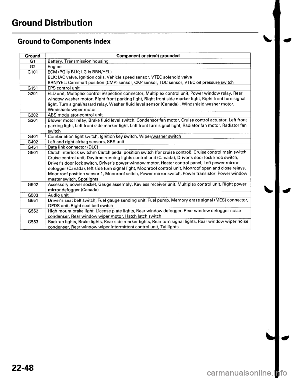
Ground Distribution
Ground to Components Index
GroundComponent or circuit qrounded
Batterv, Transmission housinq
E ngine
G 101ECM (PG is BLK; LG is BRN/YEL)
BLK: IAC valve, lgnition coils, Vehicle speed sensor, VTEC solenoid valve
BRNA/EL: Camshaft oosition (CMP) sensor. CKP sensor, TDC sensor. VTEC oil pressure switch
G 15'�]EPS control unit
G201ELD unit. Multiplex control inspection connector, Multiplex control unit, Power window relay, Rear
window washer motor, Right front parking light, Right front side marker light, Right front turn signal
light, Turn signal/hazard relay, Washer fluid level sensor (Canada) , Windshield washer motor,
Windshield wiDer motor
G202ABS modulator-control unit
G301
G401
Blower motor relay, Brake fluid level switch, Condensor fan motor, Cruise control actuator, Left front
parking light, Left front side marker light, Left front turn signal light, Radiator fan motor, Radiator fan
swrtcn
Combination liqht switch, lqnitlon kev srvitch, Wiper/wasfrer sr,virch
G402Left and riqht airbaq sensors, SRS unit
G 451Data link connector (DLC)
G501Clutch interlock switchm Clutch pedal position switch (for cruise control), Cruise control main switch,
Cruise control unit, Daytime running lights control unit (Canada), Driver's door lock knob switch,
Driver's door lock switch, Driver's power window motor, Heater control panel, Left power mirror
defogger (Canada), left side turn signal light, Moonroof control unit, Monroof open and close relays,
Moonroof position sensor '1, Moonroof seitch, Power mirror switch, Power transistor, Power window
master switch. SDotliqhts
G502Accessory power socket, Gauge assembly, Keyless receiver unit, lvlultiplex control unit, Right power
mirror defogger {Canada)
G503Audio unit
G551Driver's seat belt switch, Fuel gauge sending unit, Fuel pump, Memory erase signal (IMES) connector,
OPDS unit. Rioht seat belt switch
G552High mount brake light, License plate lights, Rear window defogger, Rear window defogger noise
condenser. Rear window wioer motor, Hatch latch switch
Back-up lights, Brake lights, Rear side marker lights, Rear turn signal lights, Rear window wiper noise
condenser, Rear window wiper intermittent control unit, Taillights
22-48
Page 900 of 1139
-a-.,_
z
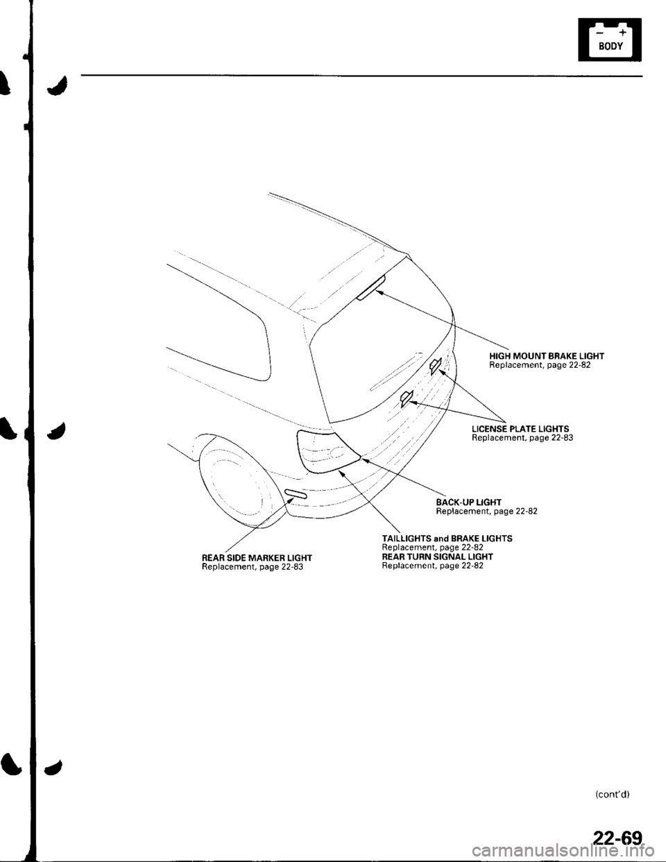
REAR SIDE MARKER LIGHTReplacement, page 22-83
HIGH MOUNT BRAKE LIGHTReplacement, page 22-82
LICENSE PLATE LIGHTSReplacement, page 22-83
BACK.UP LIGHTReplacement, page 22-82
TAILLIGHTS snd BRAKE LIGHTSReplacement, page 22-82REAR TURN SIGNAL LIGHTBeplacement, page 22-82
(cont'd)
22-69