cooling HONDA CIVIC 2016 10.G Quick Guide
[x] Cancel search | Manufacturer: HONDA, Model Year: 2016, Model line: CIVIC, Model: HONDA CIVIC 2016 10.GPages: 82, PDF Size: 5.52 MB
Page 62 of 82

116 || 117
HANDLING THE UNEXPECTED
HANDLING THE UNEXPECTED
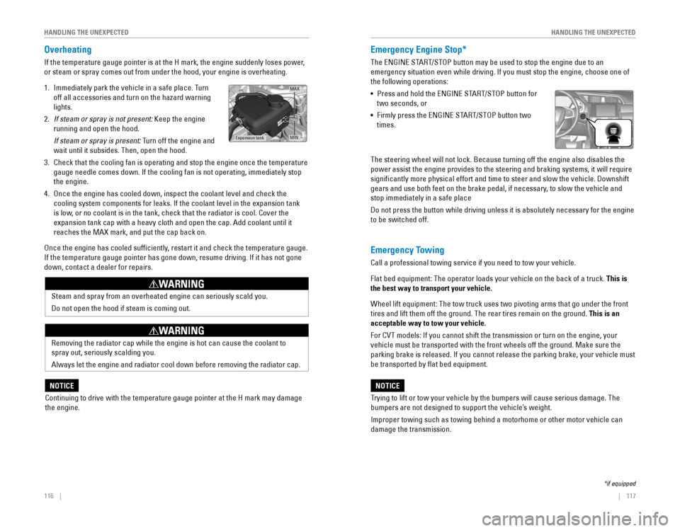
Overheating
If the temperature gauge pointer is at the H mark, the engine suddenly l\
oses power,
or steam or spray comes out from under the hood, your engine is overheat\
ing.
1. Immediately park the vehicle in a safe place. Turn
off all accessories and turn on the hazard warning
lights.
2. If steam or spray is not present: Keep the engine
running and open the hood.
If steam or spray is present: Turn off the engine and
wait until it subsides. Then, open the hood.
3. Check that the cooling fan is operating and stop the engine once the tem\
perature
gauge needle comes down. If the cooling fan is not operating, immediatel\
y stop
the engine.
4. once the engine has cooled down, inspect the coolant level and check the \
cooling system components for leaks. If the coolant level in the expansi\
on tank
is low, or no coolant is in the tank, check that the radiator is cool. Cover t\
he
expansion tank cap with a heavy cloth and open the cap. Add coolant unti\
l it
reaches the MAX mark, and put the cap back on.
once the engine has cooled sufficiently, restart it and check the temperature gauge.
If the temperature gauge pointer has gone down, resume driving. If it ha\
s not gone
down, contact a dealer for repairs.
MAX
Expansion tankMIN
Steam and spray from an overheated engine can seriously scald you.
Do not open the hood if steam is coming out.
WARNING
removing the radiator cap while the engine is hot can cause the coolant t\
o
spray out, seriously scalding you.
Always let the engine and radiator cool down before removing the radiato\
r cap.
WARNING
Continuing to drive with the temperature gauge pointer at the H mark may\
damage
the engine.
NOTICE
Emergency Engine Stop*
The eNGINe STArT/SToP button may be used to stop the engine due to an
emergency situation even while driving. If you must stop the engine, cho\
ose one of
the following operations:
•
Press and hold the eNGINe STArT/SToP button for
two seconds, or
•
Firmly press the eNGINe STArT/SToP button two
times.
The steering wheel will not lock. Because turning off the engine also di\
sables the
power assist the engine provides to the steering and braking systems, it\
will require
significantly more physical effort and time to steer and slow the vehi\
cle. Downshift
gears and use both feet on the brake pedal, if necessary, to slow the vehicle and
stop immediately in a safe place
Do not press the button while driving unless it is absolutely necessary \
for the engine
to be switched off.
*if equipped
Emergency Towing
Call a professional towing service if you need to tow your vehicle.
Flat bed equipment: The operator loads your vehicle on the back of a tru\
ck. This is
the best way to transport your vehicle.
Wheel lift equipment: The tow truck uses two pivoting arms that go under the front
tires and lift them off the ground. The rear tires remain on the ground.\
This is an
acceptable way to tow your vehicle.
For CvT models: If you cannot shift the transmission or turn on the engine, your
vehicle must be transported with the front wheels off the ground. Make s\
ure the
parking brake is released. If you cannot release the parking brake, your\
vehicle must
be transported by flat bed equipment.
Trying to lift or tow your vehicle by the bumpers will cause serious dama\
ge. The
bumpers are not designed to support the vehicle’s weight.
Improper towing such as towing behind a motorhome or other motor vehicle\
can
damage the transmission.
NOTICE
Page 66 of 82

124 || 125
HANDLING THE UNEXPECTED
HANDLING THE UNEXPECTED
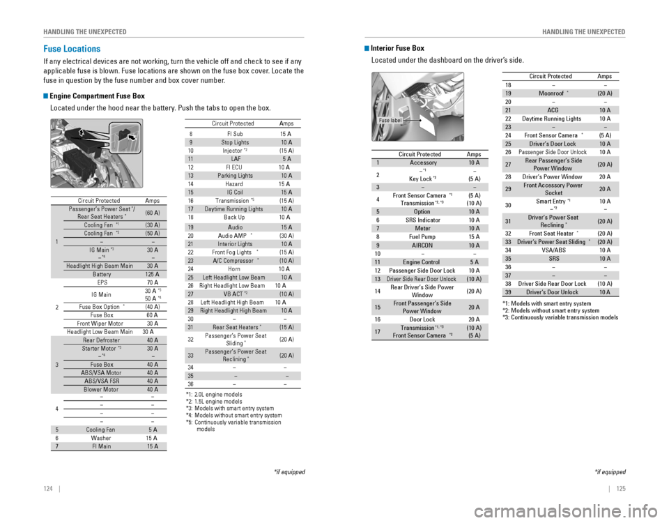
Fuse Locations
If any electrical devices are not working, turn the vehicle off and chec\
k to see if any
applicable fuse is blown. Fuse locations are shown on the fuse box cover\
. Locate the
fuse in question by the fuse number and box cover number.
Engine Compartment Fuse Box
Located under the hood near the battery. Push the tabs to open the box.
*if equipped
Circuit ProtectedAmps
1
Passenger’s Power Seat*/
Rear Seat Heaters*(60 A)
Cooling Fan*1(30 A)Cooling Fan*2(50 A)��IG Main*3
�*430 A
�
Headlight High Beam Main30 ABattery125A
2
EPS70 A
IG Main 30
A*3
50A*4
Fuse Box Option*(40 A)
Fuse Box60AFront Wiper Moto r30A
Headlight Low Beam Main 30 A
3
Rear Defroster40 AStarter Motor*3
�*430A
�
Fuse Bo x40AABS/VSA Motor40AABS/VSA FS R40ABlower Motor40A
*1: 2.0L engine models
*2: 1.5L engine models
*3: Models with smart entry syste m
*4: Models without smart entry system
4
��
��
��
��
5Cooling Fan5A
6W asher15A7FI Main15A
8F I Sub1 5A
9 Stop Lights 10A
10 Injecto r
*2(15A )
11 LAF 5A
12 FI ECU 10A
13 Parking Lights 10A
14 Hazard1 5A
15 IG Coil 15A
16 Transmission
*5(1 5A )
17 Daytime Running Lights 10A
18 Back Up 10A
Circuit Protecte
d Amps
19 Audio 15A
20 Audio AMP*(30 A)
21 Interior Lights 10A
22 Front Fog Lights
*(15 A)
23 A/C Compressor*(10 A)
24 Horn 10A
25 Left Headlight Low Beam 10A
26 Right Headlight Low Beam 10A
27 VB ACT
*2(10 A)
28 Left Headlight High Beam 10A
29 Right Headlight High Beam 10A
30 ��
31 Rear Seat Heaters
*(15 A)
32 Passenger’s Power Seat
Sliding
*(20 A)
33 Passenger’s Power Seat
Reclining
*(20 A)
34 ��
35 � �
36 ��
Circuit Protected Amps
1 Passenger’s Power Seat*/
Rear Seat Heaters*(60 A)
Cooling Fan
*1(30 A)
Cooling Fan*2(50 A)
� �
IG Main
*3
�*430 A
�
Headlight High Beam Main 30A
Battery 125A
2 EPS
70A
IG Main 30
A
*3
50A*4
Fuse Box Option*(40 A)
Fuse Bo x6 0A
Front Wiper Moto r30A
Headlight Low Beam Main 30 A
3 Rear Defroster
40A
Starter Motor
*3
�*430 A
�
Fuse Bo x 40A
ABS/VSA Motor 40A
ABS/VSA FS R 40A
Blower Motor 40A
*1: 2.0L engine models
*2: 1.5L engine models
*3: Models with smart entry syste m
*4: Models without smart entry system
*5: Continuously variable transmission
models
4 ��
��
��
��
5 Cooling Fan 5A
6W asher1 5A
7 FI Main 15A
8F I Sub15A9Stop Lights10A
10 Injecto r*2(15A )11LAF5A
12 FI ECU 10A
13Parking Lights10 A
14 Hazard15A15IG Coil15A
16 Transmission*5(1 5A )17Daytime Running Lights10A
18 Back Up 10A
Circuit Protecte dAmps
19Audio15A
20 Audio AMP*(30 A)21Interior Lights10A
22 Front Fog Lights*(15 A)23A/C Compressor*(10 A)
24 Horn 10A
25Left Headlight Low Beam10A
26 Right Headlight Low Beam 10A
27VB ACT*2(10 A)
28 Left Headlight High Beam 10A
29Right Headlight High Beam10A
30��31Rear Seat Heaters*(15 A)
32 Passenger’s Power Seat
Sliding
*(20 A)
33Passenger’s Power Seat Reclining*(20 A)
34
��35��
36��
Interior Fuse Box
Located under the dashboard on the driver’s side.
*if equipped
Circuit ProtectedAmps1Accessory10 A
2�*1
Key Lock*2�
(5 A)
3��
4Front Sensor Camera*1
Transmission*2, *3(5A)
(10 A)
5Optio n10A6SRS Indicator10A7Meter10A8Fuel Pump15A
*3: Continuously variable transmission models
9AIRCON10A10��11Engine Control5A12Passenger Side Door Lock10A13Driver Side Rear Door Unloc k(10A )
14Rear Driver’s Side Power
Window(20A )
15Front Passenger’s Side
Power Windo w20A
16Door Lock20A
17Transmissio n*1, *3
Front Sensor Camera*2(10A )
(5 A)
18 ��
19 Moonroo f*(20A )
20 � �
21 ACG 10A
22 Daytime Running Lights 10A
23 � �
24 Front Sensor Camera
*(5 A)
25 Driver’s Door Lock 10A
26
Passen ger Side Door Unlock10A
27 Rear Passenger’s Side
Power Window (2
0A )
*1: Models with smart entry system
*2: Models without smart entry system 28
Driver’s Power Window 20A
29 Front Accessory Power
Socket 20
A
30 Smart Entry
*1
�*210
A
�
31 Driver’s Power Seat
Reclining
*(20 A)
32 Front Seat Heater
*(20 A)
33 Driver’s Power Seat Sliding*(20 A)
34 VSA/ABS 10A
35 SRS 10A
36 � �
37 ��
38 Driver Side Rear Door Lock (10 A)
39 Driver’s Door Unlock 10 A
Circuit Protecte
dAmps
Fuse label
Circuit Protected Amps
1 Accessory 10A
2 �
*1
Key Lock*2�
(5 A)
3 � �
4 Front Sensor Camera
*1
Transmission*2, *3(5
A)
(10 A)
5 Option 10A
6 SRS Indicator 10A
7 Meter 10A
8 Fuel Pump 15A
*3
: Continuously variable transmission models
9 AIRCON 10A
10 � �
11 Engine Control 5A
12 Passenger Side Door Lock 10A
13
Driver Side Rear Door Unloc k(10A )
14 Rear Driver’s Side Power
Window (2
0A )
15 Front Passenger’s Side
Power Windo w20
A
16 Door Lock 20A
17 Transmissio
n
*1, *3
Front Sensor Camera*2(10A )
(5 A)
18��19Moonroo f*(20A )20��21ACG10A22Daytime Running Lights10A23��24Front Sensor Camera*(5 A)25Driver’s Door Lock10A26Passen ger Side Door Unlock10A
27Rear Passenger’s Side
Power Window(20A )
*1: Models with smart entry system*2: Models without smart entry system
28Driver’s Power Window20 A
29 Front Accessory Power
Socket 20
A
30Smart Entry*1
�*210A
�
31 Driver’s Power Seat
Reclining
*(20 A)
32Front Seat Heater*(20 A)
33 Driver’s Power Seat Sliding*(20 A)34VSA/ABS10A
35 SRS 10A
36��
37��38Driver Side Rear Door Lock(10 A)
39 Driver’s Door Unlock 10 A
Circuit Protecte dAmps
Page 72 of 82

136 || 137
M
AINTENANCEMAINTENANCE
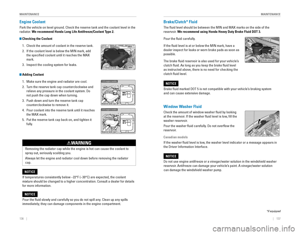
Engine Coolant
Park the vehicle on level ground. Check the reserve tank and the coolant\
level in the
radiator. We recommend Honda Long Life Antifreeze/Coolant Type 2.
Checking the Coolant
1. Check the amount of coolant in the reserve tank.
2. If the coolant level is below the MIN mark, add
the specified coolant until it reaches the MAX
mark.
3. Inspect the cooling system for leaks.
Adding Coolant
1. Make sure the engine and radiator are cool.
2. Turn the reserve tank cap counterclockwise and
relieve any pressure in the coolant system. Do
not push the cap down when turning.
3. Push down and turn the reserve tank cap
counterclockwise to remove it.
4. Pour coolant into the reserve tank until it reaches
the MAX mark.
5. Put the reserve tank cap back on, and tighten it
fully.
If temperatures consistently below −22°F (−30°C) are expec\
ted, the coolant
mixture should be changed to a higher concentration. Consult a dealer fo\
r details
for more information.
NOTICE
Reserve tank cap
1.5 � engine models
Reserve tank cap
2.0 � engine models
removing the radiator cap while the engine is hot can cause the coolant t\
o
spray out, seriously scalding you.
Always let the engine and radiator cool down before removing the radiato\
r
cap.
WARNING
Pour the fluid slowly and carefully so you do not spill any. Clean up any spills
immediately; they can damage components in the engine compartment.
NOTICE
MA X
MINReserve tan k
Window Washer Fluid
Check the amount of window washer fluid by looking
at the reservoir. If the washer fluid level is low, fill the
washer reservoir.
Pour the washer fluid carefully. Do not overflow the
reservoir.
Canadian models
If the washer fluid level is low, the washer level indicator or a message appears in
the Driver Information Interface.
Do not use engine antifreeze or a vinegar/water solution in the windshie\
ld washer
reservoir. Antifreeze can damage your vehicle’s paint. A vinegar/water solution
can damage the windshield washer pump.
NOTICE
Brake/Clutch* Fluid
The fluid level should be between the MIN and MAX marks on the side of\
the
reservoir. We recommend using Honda Heavy Duty Brake Fluid DOT 3.
Pour the fluid carefully.
If the fluid level is at or below the MIN mark, have a
dealer inspect for leaks or worn brake pads as soon as
possible.
The brake fluid reservoir is also used for your vehicle’s
clutch fluid. As long as you keep the brake fluid level
as instructed above, there is no need for checking the
clutch fluid level.
Brake fluid marked DoT 5 is not compatible with your vehicle’s braking system
and can cause extensive damage.
NOTICE
Brake reservoir
MINMAX
*if equipped
Page 76 of 82

144 || 145
M
AINTENANCEMAINTENANCE
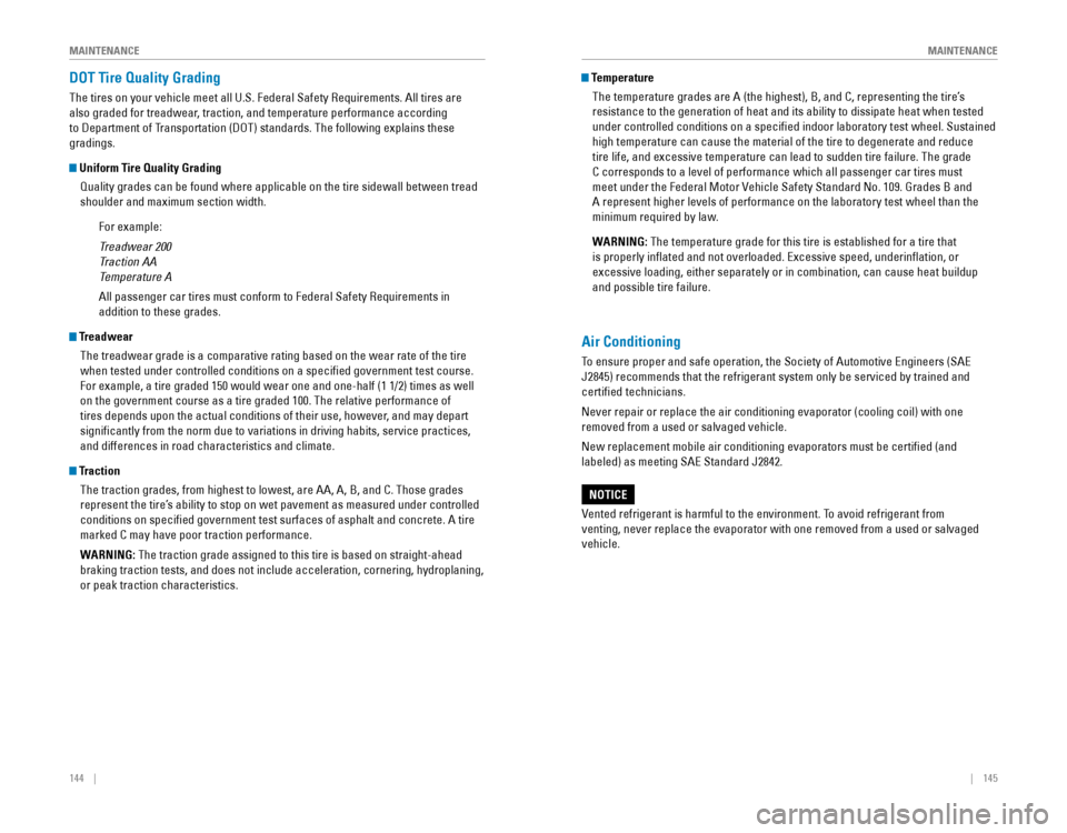
DOT Tire Quality Grading
The tires on your vehicle meet all U.S. Federal Safety requirements. All tires are
also graded for treadwear, traction, and temperature performance according
to Department of Transportation (DoT) standards. The following explains these
gradings.
Uniform Tire Quality Grading
Quality grades can be found where applicable on the tire sidewall betwee\
n tread
shoulder and maximum section width.
For example:
Treadwear 200
Traction AA
Temperature A
All passenger car tires must conform to Federal Safety requirements in
addition to these grades.
TreadwearThe treadwear grade is a comparative rating based on the wear rate of th\
e tire
when tested under controlled conditions on a specified government test\
course.
For example, a tire graded 150 would wear one and one-half (1 1/2) tim\
es as well
on the government course as a tire graded 100. The relative performance \
of
tires depends upon the actual conditions of their use, however, and may depart
significantly from the norm due to variations in driving habits, servi\
ce practices,
and differences in road characteristics and climate.
TractionThe traction grades, from highest to lowest, are AA, A, B, and C. Those \
grades
represent the tire’s ability to stop on wet pavement as measured under controlled
conditions on specified government test surfaces of asphalt and concre\
te. A tire
marked C may have poor traction performance.
WARNING: The traction grade assigned to this tire is based on straight-ahead
braking traction tests, and does not include acceleration, cornering, hy\
droplaning,
or peak traction characteristics.
Temperature
The temperature grades are A (the highest), B, and C, representing the\
tire’s
resistance to the generation of heat and its ability to dissipate heat w\
hen tested
under controlled conditions on a specified indoor laboratory test whee\
l. Sustained
high temperature can cause the material of the tire to degenerate and re\
duce
tire life, and excessive temperature can lead to sudden tire failure. Th\
e grade
C corresponds to a level of performance which all passenger car tires must
meet under the Federal Motor vehicle Safety Standard No. 109. Grades B and
A represent higher levels of performance on the laboratory test wheel th\
an the
minimum required by law.
WARNING: The temperature grade for this tire is established for a tire that
is properly inflated and not overloaded. excessive speed, underinflation, or
excessive loading, either separately or in combination, can cause heat b\
uildup
and possible tire failure.
Air Conditioning
To ensure proper and safe operation, the Society of Automotive engineers (SAe
J2845) recommends that the refrigerant system only be serviced by train\
ed and
certified technicians.
Never repair or replace the air conditioning evaporator (cooling coil)\
with one
removed from a used or salvaged vehicle.
New replacement mobile air conditioning evaporators must be certified \
(and
labeled) as meeting SAe Standard J2842.
vented refrigerant is harmful to the environment. To avoid refrigerant from
venting, never replace the evaporator with one removed from a used or sa\
lvaged
vehicle.
NOTICE