stop start HONDA CIVIC HYBRID 2015 9.G Quick Guide
[x] Cancel search | Manufacturer: HONDA, Model Year: 2015, Model line: CIVIC HYBRID, Model: HONDA CIVIC HYBRID 2015 9.GPages: 65, PDF Size: 3.32 MB
Page 4 of 65
| 1
VISUAL INDEX
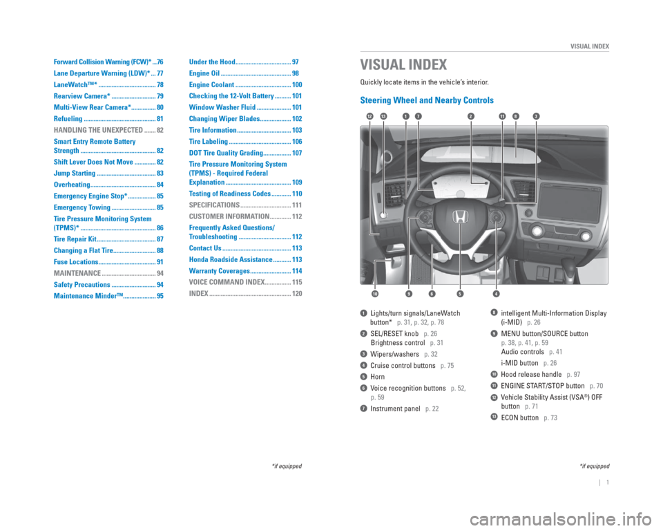
Quickly locate items in the vehicle’s interior.
Steering Wheel and Nearby Controls
1 Lights/turn signals/LaneWatch
button* p. 31, p. 32, p. 78
2 SEL/RESET knob p. 26
Brightness control p. 31
3 Wipers/washers p. 32
4 Cruise control buttons p. 75
5 Horn
6 Voice recognition buttons p. 52,
p. 59
7 Instrument panel p. 22
8 intelligent Multi-Information Display
(i-MID) p. 26
9 MENU button/SOURCE button
p. 38, p. 41, p. 59
Audio controls p. 41
i-MID button p. 26
10 Hood release handle p. 97
11 ENGINE START/STOP button p. 70
12 Vehicle Stability Assist (VSA®) OFF
button p. 71
13 ECON button p. 73
VISUAL INDEX
*if equipped
1128
54
11
10
72313
69
*if equipped
Forward Collision Warning (FCW)* ...76
Lane Departure Warning (LDW)* ... 77
LaneWatch™* ................................... 78
Rearview Camera* ........................... 79
Multi-View Rear Camera* ............... 80
Refueling ............................................ 81
HANDLING THE UNEXPECTED ....... 82
Smart Entry Remote Battery
Strength .............................................. 82
Shift Lever Does Not Move ............. 82
Jump Starting .................................... 83
Overheating ........................................ 84
Emergency Engine Stop* ................. 85
Emergency Towing ........................... 85
Tire Pressure Monitoring System
(TPMS)* .............................................. 86
Tire Repair Kit .................................... 87
Changing a Flat Tire .......................... 88
Fuse Locations ................................... 91
MAINTENANCE ................................. 94
Safety Precautions ........................... 94
Maintenance Minder™.................... 95 Under the Hood .................................. 97
Engine Oil ........................................... 98
Engine Coolant .................................. 100
Checking the 12-Volt Battery .......... 101
Window Washer Fluid ..................... 101
Changing Wiper Blades ................... 102
Tire Information ................................. 103
Tire Labeling ...................................... 106
DOT Tire Quality Grading ................. 107
Tire Pressure Monitoring System
(TPMS) - Required Federal
Explanation ........................................ 109
Testing of Readiness Codes ............ 110
SPECIFICATIONS ............................... 111
CUSTOMER INFORMATION ............. 112
Frequently Asked Questions/
Troubleshooting ................................ 112
Contact Us .......................................... 113
Honda Roadside Assistance ........... 113
Warranty Coverages ......................... 114
VOICE COMMAND INDEX ................ 115
INDEX .................................................. 120
Page 6 of 65
4 || 5
SAFETY
SAFETY
Carbon Monoxide Gas
The engine exhaust from this vehicle contains carbon monoxide, a colorle\
ss,
odorless, and highly toxic gas. As long as you properly maintain your ve\
hicle and
follow the instructions set forth below, you will not accumulate dangerous levels
of carbon monoxide gas in the vehicle interior.
Have the exhaust system inspected for leaks whenever:
• The exhaust system is making an unusual noise.
• The exhaust system may have been damaged.
• The vehicle is raised for an oil change. When you operate a vehicle with the trunk open, airfl ow can pull exhaust gas
into the interior and create a hazardous condition. If you must drive wi\
th the trunk
open, open all the windows and set the climate control system as shown b\
elow.
1. Select the fresh air mode.
2. Select the
mode.
3. Set the fan speed to high.
4. Set the temperature control to a comfortable setting.
Adjust the climate control system in the same manner if you sit in your \
parked
vehicle with the engine running.
An enclosed area such as a garage can quickly fi ll up with carbon monoxide gas.
Do not run the engine with the garage door closed. Even when the garage \
door is
open, drive out of the garage immediately after starting the engine. Carbon monoxide gas is toxic. Breathing it can cause unconsciousness and\
even kill you.
Avoid any enclosed areas or activities that expose you to carbon monoxide\
.
WARNING
Seat Belts
A seat belt is your best protection in all types of collisions. Airbags \
are designed to
supplement seat belts, not replace them. So even though your vehicle is \
equipped
with airbags, make sure you and your passengers always wear your seat be\
lts and
wear them properly.
Lap/Shoulder Seat Belts
All fi ve seating positions are equipped with lap/shoulder seat belts with
emergency locking retractors. In normal driving, the retractor lets you \
move
freely while keeping some tension on the belt. During a collision or sud\
den stop,
the retractor locks to restrain your body. The rear seat belts also have a lockable
retractor for use with child seats.
The front seats are equipped with automatic seat belt tensioners to enha\
nce
safety. The tensioners automatically tighten the front seat belts during a mod\
erate
to severe frontal collision, sometimes even if the collision is not seve\
re enough to
infl ate the front airbags.
Proper Use of Seat BeltsFollow these guidelines for proper use:
• All occupants should sit upright, well back in the seat, and remain in t\
hat position for the duration of the trip. Slouching and leaning reduces the\
effectiveness of the belt and can increase the chance of serious injury \
in a
crash.
• Never place the shoulder part of a lap/shoulder seat belt under your arm\
or behind your back. This could cause very serious injuries in a crash.
• Two people should never use the same seat belt. If they do, they could be\
very seriously injured in a crash.
• Do not put any accessories on the seat belts. Devices intended to improv\
e comfort or reposition the shoulder part of a seat belt can reduce the pr\
otective
capability and increase the chance of serious injury in a crash.
• No one should sit in a seat with an inoperative seat belt or one that do\
es not appear to be working correctly. Using a seat belt that is not working properly
may not protect the occupant in a crash. Have a dealer check the belt as\
soon
as possible.
Not wearing a seat belt properly increases the chance of a serious injur\
y or
death in a crash, even though your vehicle has airbags.
Be sure you and your passengers always wear seat belts and wear them
properly.
WARNING
Page 15 of 65
22 || 23
INSTRUMENT PANEL
INSTRUMENT PANEL
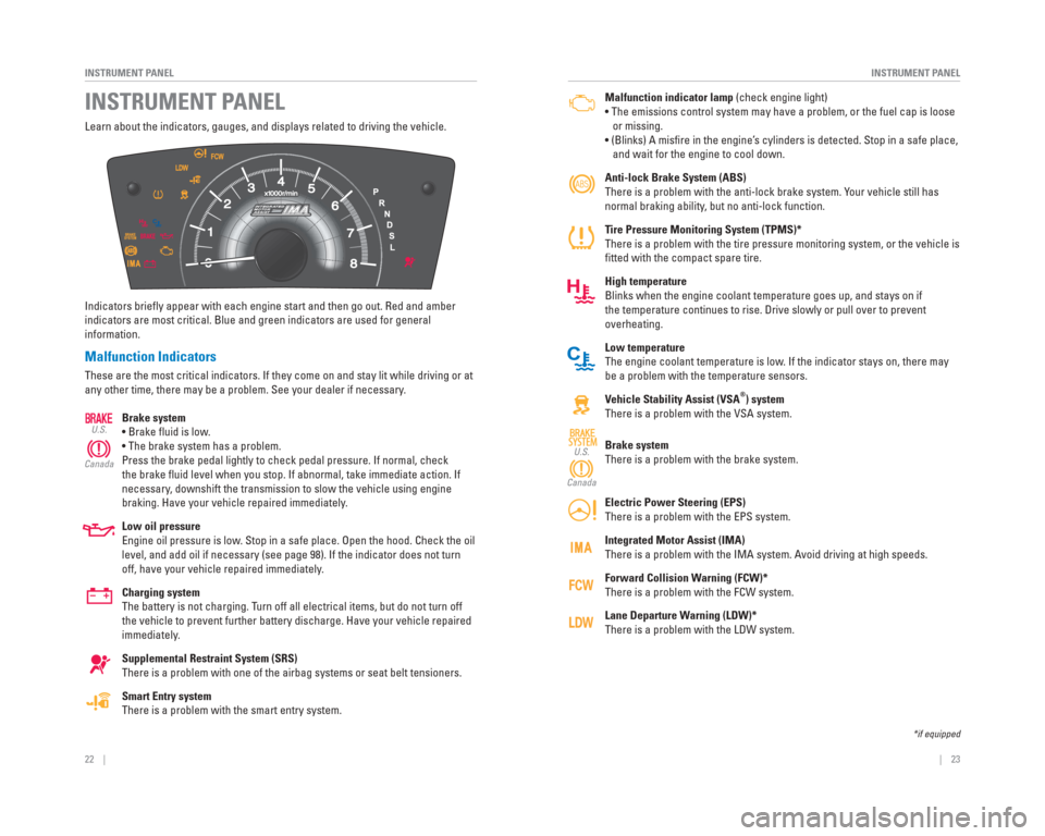
Learn about the indicators, gauges, and displays related to driving the \
vehicle.
Indicators briefl y appear with each engine start and then go out. Red and amber
indicators are most critical. Blue and green indicators are used for gen\
eral
information.
Malfunction Indicators
These are the most critical indicators. If they come on and stay lit whi\
le driving or at
any other time, there may be a problem. See your dealer if necessary.
Brake system
• Brake fl uid is low.
• The brake system has a problem.
Press the brake pedal lightly to check pedal pressure. If normal, check \
the brake fl uid level when you stop. If abnormal, take immediate action. If
necessary, downshift the transmission to slow the vehicle using engine
braking. Have your vehicle repaired immediately.
Low oil pressure
Engine oil pressure is low. Stop in a safe place. Open the hood. Check the oil
level, and add oil if necessary (see page 98). If the indicator does n\
ot turn
off, have your vehicle repaired immediately.
Charging system
The battery is not charging. Turn off all electrical items, but do not turn off
the vehicle to prevent further battery discharge. Have your vehicle repa\
ired
immediately.
Supplemental Restraint System (SRS)
There is a problem with one of the airbag systems or seat belt tensioner\
s.
Smart Entry system
There is a problem with the smart entry system.
U.S.
Canada
INSTRUMENT PANEL Malfunction indicator lamp (check engine light)
• The emissions control system may have a problem, or the fuel cap is\
loose
or missing.
• (Blinks) A misfi re in the engine’s cylinders is detected. Stop in a safe place,
and wait for the engine to cool down.
Anti-lock Brake System ( ABS)
There is a problem with the anti-lock brake system. Your vehicle still has
normal braking ability, but no anti-lock function.
Tire Pressure Monitoring System ( TPMS)*
There is a problem with the tire pressure monitoring system, or the vehi\
cle is
fi tted with the compact spare tire.
High temperature
Blinks when the engine coolant temperature goes up, and stays on if
the temperature continues to rise. Drive slowly or pull over to prevent \
overheating.
Low temperature
The engine coolant temperature is low. If the indicator stays on, there may
be a problem with the temperature sensors.
Vehicle Stability Assist ( VSA
®) system
There is a problem with the VSA system.
Brake system
There is a problem with the brake system.
Electric Power Steering (EPS)
There is a problem with the EPS system.
Integrated Motor Assist ( IMA)
There is a problem with the IMA system. Avoid driving at high speeds.
Forward Collision Warning (FCW)*
There is a problem with the FCW system.
Lane Departure Warning (LDW)*
There is a problem with the LDW system.
SYSTEMSYSTEMU.S.
Canada
*if equipped
Page 16 of 65
24 || 25
INSTRUMENT PANEL
INSTRUMENT PANEL
Condition Indicators
These indicators may require you to perform an action.
Parking brake
Release the parking brake before driving. You will hear a beep if you drive
with it not fully released.
Seat belt reminder
Make sure seat belts are fastened for you and all passengers. The indica\
tor
blinks and beeps sound continuously if you or your front passenger has n\
ot
fastened your seat belts when you begin driving. If the indicator remain\
s on
after seat belts are fastened, see your dealer.
Door open
A door is not closed. A beep sounds while driving.
Trunk open
The trunk is not closed.
Low fuel
Refuel as soon as possible. If the indicator blinks, there is a problem \
with the
fuel gauge. See your dealer.
Low tire pressure
Stop in a safe place, check tire pressures, and infl ate tire(s) if necessary.
The indicator also appears if your vehicle is fi tted with the compact spare
tire. Have your regular tire repaired or replaced as soon as possible.
U.S.
Canada
System message
When a condition or malfunction indicator comes on, a message also
appears on the multi-information display. Check the display for more
information.
Immobilizer
Your remote transmitter cannot be recognized by the vehicle. If the indic\
ator
blinks, you may not be able to start the engine. Turn the vehicle off, and then
on again. If it continues to blink, there may be a problem with the syst\
em.
See your dealer.
On/Off Indicators
These indicators remind you when an item is on or off.
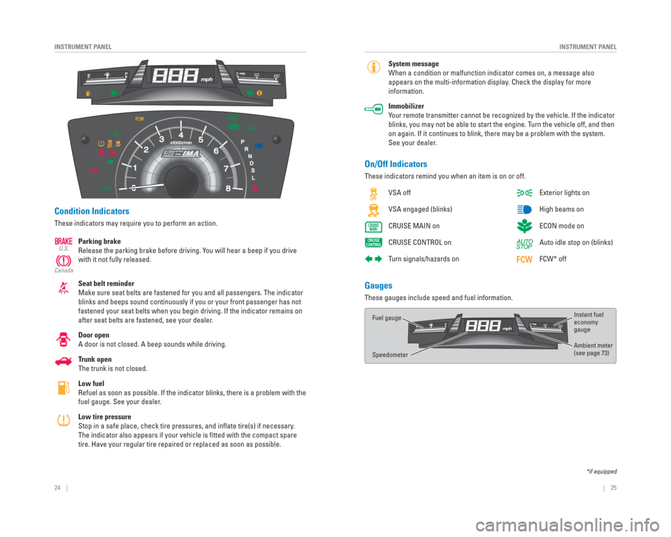
Gauges
These gauges include speed and fuel information. VSA off
VSA engaged (blinks)
CRUISE MAIN on
CRUISE CONTROL on
Turn signals/hazards on
*if equipped
Exterior lights on
High beams on
ECON mode on
Auto idle stop on (blinks)
FCW* off
Instant fuel
economy
gauge
Ambient meter
(see page 73)
Fuel gauge
Speedometer
Page 39 of 65
70 || 71
DRIVING
DRIVING
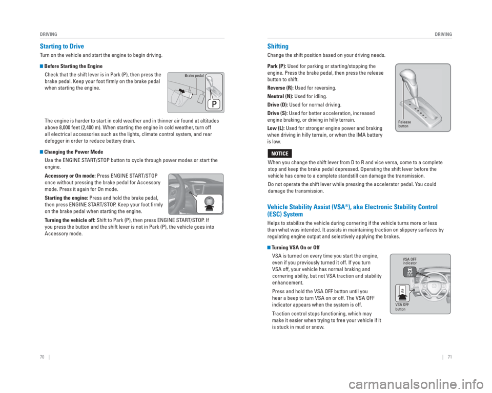
Starting to Drive
Turn on the vehicle and start the engine to begin driving.
Before Starting the Engine
Check that the shift lever is in Park (P), then press the
brake pedal. Keep your foot fi rmly on the brake pedal
when starting the engine.
The engine is harder to start in cold weather and in thinner air found a\
t altitudes
above 8,000 feet (2,400 m). When starting the engine in cold weather, turn off
all electrical accessories such as the lights, climate control system, a\
nd rear
defogger in order to reduce battery drain.
Changing the Power Mode Use the ENGINE START/STOP button to cycle through power modes or start the
engine.
Accessory or On mode: Press ENGINE START/STOP
once without pressing the brake pedal for Accessory
mode. Press it again for On mode.
Starting the engine: Press and hold the brake pedal,
then press ENGINE START/STOP. Keep your foot fi rmly
on the brake pedal when starting the engine.
Turning the vehicle off: Shift to Park (P), then press ENGINE START/STOP. If
you press the button and the shift lever is not in Park (P), the vehic\
le goes into
Accessory mode.
Brake pedal
Shifting
Change the shift position based on your driving needs.
Park (P): Used for parking or starting/stopping the
engine. Press the brake pedal, then press the release
button to shift.
Reverse (R): Used for reversing.
Neutral (N): Used for idling.
Drive (D): Used for normal driving.
Drive (S): Used for better acceleration, increased
engine braking, or driving in hilly terrain.
Low (L): Used for stronger engine power and braking
when driving in hilly terrain, or when the IMA battery
is low .
When you change the shift lever from D to R and vice versa, come to a co\
mplete
stop and keep the brake pedal depressed. Operating the shift lever befor\
e the
vehicle has come to a complete standstill can damage the transmission.
Do not operate the shift lever while pressing the accelerator pedal. Y ou could
damage the transmission.
NOTICE
Release
button
VSA OFF
indicator
VSA OFF
button
V ehicle Stability Assist (VSA®), aka Electronic Stability Control
(ESC) System
Helps to stabilize the vehicle during cornering if the vehicle turns mor\
e or less
than what was intended. It assists in maintaining traction on slippery s\
urfaces by
regulating engine output and selectively applying the brakes.
Turning VSA On or Off
VSA is turned on every time you start the engine,
even if you previously turned it off. If you turn
VSA off, your vehicle has normal braking and
cornering ability, but not VSA traction and stability
enhancement.
Press and hold the VSA OFF button until you
hear a beep to turn VSA on or off. The VSA OFF
indicator appears when the system is off.
Traction control stops functioning, which may
make it easier when trying to free your vehicle if it
is stuck in mud or snow.
Page 41 of 65
74 || 75
DRIVING
DRIVING
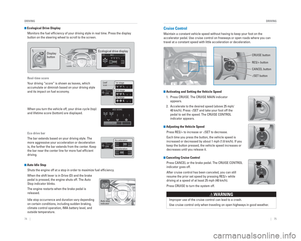
Ecological Drive Display
Monitors the fuel effi ciency of your driving style in real time. Press the display
button on the steering wheel to scroll to the screen.
Display
button Ecological drive display
Real-time score
Your driving “score” is shown as leaves, which
accumulate or diminish based on your driving style
and its impact on fuel economy.
When you turn the vehicle off, your drive cycle (top)
and lifetime score (bottom) are displayed.
Eco drive bar
The bar extends based on your driving style. The
more aggressive your acceleration or deceleration
is, the farther the bar extends from the center. Keep
the bar near the center line for more fuel effi cient
driving.
1st stage
2nd stage
3rd stage
Leaf
icon
Acceleration
Deceleration
Auto Idle Stop
Shuts the engine off at a stop in order to maximize fuel effi ciency.
When the shift lever is in Drive (D) and the brake
pedal is pressed, the engine shuts off. The Auto
Stop indicator blinks.
The engine restarts when the brake pedal is
released.
Idle stop occurrence and duration vary depending
on certain conditions, including sudden braking,
climate control operation, IMA battery level, and
outside temperature.
Auto stop
indicator
Cruise Control
Maintain a constant vehicle speed without having to keep your foot on th\
e
accelerator pedal. Use cruise control on freeways or open roads where yo\
u can
travel at a constant speed with little acceleration or deceleration.
Activating and Setting the Vehicle Speed
1. Press CRUISE. The CRUISE MAIN indicator appears.
2. Accelerate to the desired speed (above 25 mph/ 40 km/h). Press -/SET and take your foot off the
pedal to set the speed. The CRUISE CONTROL
indicator appears.
Adjusting the Vehicle Speed
Press RES/+ to increase or -/SET to decrease.
Each time you press the button, the vehicle speed is
increased or decreased by about 1 mph (1.6 km/h). If you
keep the button pressed, the vehicle speed increases or
decreases until you release it.
Canceling Cruise ControlPress CANCEL or the brake pedal. The CRUISE CONTROL
indicator goes off.
After cruise control has been canceled, you can still
resume the prior set speed by pressing RES/+ while
driving at a speed of at least 25 mph (40 km/h).
Press CRUISE to turn the system off.
Improper use of the cruise control can lead to a crash.
Use cruise control only when traveling on open highways in good weather .
WARNING
CRUISE button
RES/+ button
-/SET button CANCEL button
Page 45 of 65
82 || 83
HANDLING THE UNEXPECTED
HANDLING THE UNEXPECTED
Learn about what to do in critical or emergency situations.
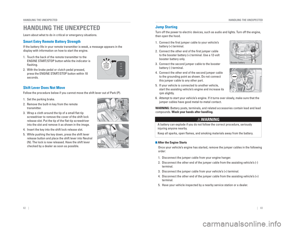
Smart Entry Remote Battery Strength
If the battery life in your remote transmitter is weak, a message appear\
s in the
display with information on how to start the engine.
1. Touch the back of the remote transmitter to the
ENGINE START/STOP button while the indicator is
fl ashing.
2. With the brake pedal or clutch pedal pressed, press the ENGINE START/STOP button within 10
seconds.
HANDLING THE UNEXPECTED
Booster battery
WARNING: Battery posts, terminals, and related accessories contain lead and lead\
compounds. Wash your hands after handling.
A battery can explode if you do not follow the correct procedure, seriou\
sly
injuring anyone nearby.
Keep all sparks, open fl ames, and smoking materials away from the battery.
WARNING
After the Engine StartsOnce your vehicle’s engine has started, remove the jumper cables in the following
order:
1. Disconnect the jumper cable from your engine hanger.
2. Disconnect the other end of the jumper cable from the assisting vehicle’\
s (-) terminal.
3. Disconnect the jumper cable from your vehicle’s (+) terminal.
4. Disconnect the other end of the jumper cable from the assisting vehicle’\
s (+) terminal.
5. Have your vehicle inspected by a nearby service station or a dealer.
Shift Lever Does Not Move
Follow the procedure below if you cannot move the shift lever out of Par\
k (P).
1. Set the parking brake.
2. Remove the built-in key from the remote transmitter.
3. Wrap a cloth around the tip of a small fl at-tip screwdriver to remove the cover of the shift lock
release slot. Put the tip of the fl at-tip screwdriver
into the slot and remove it as shown in the image.
4. Insert the key into the shift lock release slot.
5. While pushing the key down, press the shift lever release button and place the shift lever into Neutral
(N). The lock is now released. Have the shift lever
checked by a dealer as soon as possible.
Slot
Cover
Release
button Shift lock
release slot
Jump
Starting
Turn off the power to electric devices, such as audio and lights. T urn off the engine,
then open the hood.
1. Connect the fi rst jumper cable to your vehicle’ s
battery (+) terminal.
2. Connect the other end of the fi rst jumper cable
to the booster battery (+) terminal. Use a 12-volt
booster battery only .
3. Connect the second jumper cable to the booster
battery (-) terminal.
4. Connect the other end of the second jumper cable
to the grounding point as shown. Do not connect
this jumper cable to any other part.
5. If your vehicle is connected to another vehicle,
start the assisting vehicle’ s engine and increase its
rpm slightly .
6. Attempt to start your vehicle’ s engine. If it turns over slowly , make sure that the
jumper cables have good metal-to-metal contact.
Page 46 of 65
84 || 85
HANDLING THE UNEXPECTED
HANDLING THE UNEXPECTED
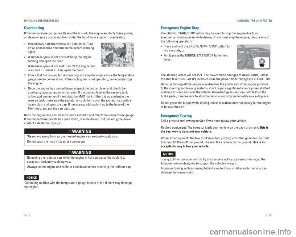
Overheating
If the temperature gauge needle is at the H mark, the engine suddenly lo\
ses power,
or steam or spray comes out from under the hood, your engine is overheat\
ing.
1. Immediately park the vehicle in a safe place. Turn
off all accessories and turn on the hazard warning
lights.
2. If steam or spray is not present: Keep the engine
running and open the hood.
If steam or spray is present: Turn off the engine and wait until it subsides. Then, open the hood.
3. Check that the cooling fan is operating and stop the engine once the tem\
perature gauge needle comes down. If the cooling fan is not operating, immediatel\
y stop
the engine.
4. Once the engine has cooled down, inspect the coolant level and check the\
cooling system components for leaks. If the coolant level in the reserve\
tank
is low, add coolant until it reaches the MAX mark. If there is no coolant in t\
he
reserve tank, make sure the radiator is cool, then cover the radiator ca\
p with a
heavy cloth and open the cap. If necessary, add coolant up to the base of the
fi ller neck, and put the cap back on.
Once the engine has cooled suffi ciently, restart it and check the temperature gauge.
If the temperature needle has gone down, resume driving. If it has not g\
one down,
contact a dealer for repairs.
Steam and spray from an overheated engine can seriously scald you.
Do not open the hood if steam is coming out.
WARNING
Removing the radiator cap while the engine is hot can cause the coolant \
to
spray out, seriously scalding you.
Always let the engine and radiator cool down before removing the radiato\
r cap.
WARNING
Continuing to drive with the temperature gauge needle at the H mark may \
damage
the engine.
NOTICE
Reserve
tank
MAX
MIN
Emergency Engine Stop
The ENGINE START/STOP button may be used to stop the engine due to an
emergency situation even while driving. If you must stop the engine, cho\
ose one of
the following operations:
• Press and hold the ENGINE START/STOP button for two seconds, or
• Firmly press the ENGINE START/STOP button two times.
The steering wheel will not lock. The power mode changes to ACCESSORY, unless
the shift lever is in Park (P), in which case the power mode changes t\
o VEHICLE OFF.
Because turning off the engine also disables the power assist the engine\
provides
to the steering and braking systems, it will require signifi cantly more physical effort
and time to steer and slow the vehicle. Downshift gears and use both fee\
t on the
brake pedal, if necessary, to slow the vehicle and stop immediately in a safe place
Do not press the button while driving unless it is absolutely necessary \
for the engine
to be switched off.
Emergency Towing
Call a professional towing service if you need to tow your vehicle.
Flat bed equipment: The operator loads your vehicle on the back of a tru\
ck. This is
the best way to transport your vehicle.
Wheel lift equipment: The tow truck uses two pivoting arms that go under\
the front
tires and lift them off the ground. The rear tires remain on the ground.\
This is an
acceptable way to tow your vehicle.
Trying to lift or tow your vehicle by the bumpers will cause serious dama\
ge. The
bumpers are not designed to support the vehicle’s weight.
Improper towing such as towing behind a motorhome or other motor vehicle\
can
damage the transmission.
NOTICE
Page 49 of 65
90 || 91
HANDLING THE UNEXPECTED
HANDLING THE UNEXPECTED
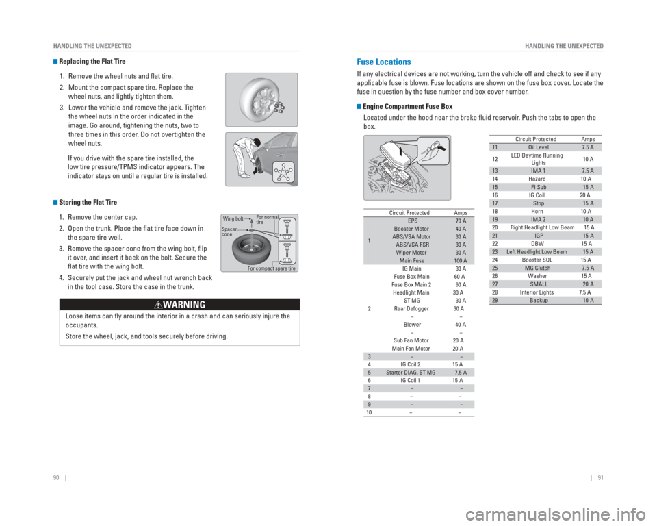
Fuse Locations
If any electrical devices are not working, turn the vehicle off and chec\
k to see if any
applicable fuse is blown. Fuse locations are shown on the fuse box cover\
. Locate the
fuse in question by the fuse number and box cover number.
Engine Compartment Fuse Box
Located under the hood near the brake fl uid reservoir. Push the tabs to open the
box.
11Oil Level7.5 A
12 LED Daytime Running
Lights 10 A
13IMA 17.5 A
14 Hazard 10 A
15FI Sub15 A
16 IG Coil 20 A
17Stop15 A
18 Horn 10 A
19IMA 210 A
20 Right Headlight Low Beam 15 A
21IGP15 A
22 DBW 15 A
23Left Headlight Low Beam15 A
24 Booster SOL 15 A
25MG Clutch7.5 A
26 Washer 15 A
27SMALL20 A
28 Interior Lights 7.5 A
29Backup10 A
Circuit ProtectedAmps
Circuit ProtectedAmps
1
EPS70 ABooster Motor40 AABS/VSA Motor30 AABS/VSA FSR30 AWiper Motor30 AMain Fuse100 A
2
IG Main30 A
Fuse Box Main 60 A
Fuse Box Main 260 A
Headlight Main 30 A
ST MG30 A
Rear Defogger 30 A −−
Blower 40 A
−−
Sub Fan Motor 20 A
Main Fan Motor 20 A
3−−
4 IG Coil 2 15 A
5Starter DIAG, ST MG7.5 A
6 IG Coil 1 15 A
7−−
8− −
9−−
10 − −
Replacing the Flat Tire
1. Remove the wheel nuts and fl at tire.
2. Mount the compact spare tire. Replace the wheel nuts, and lightly tighten them.
3. Lower the vehicle and remove the jack. Tighten the wheel nuts in the order indicated in the
image. Go around, tightening the nuts, two to
three times in this order. Do not overtighten the
wheel nuts.
If you drive with the spare tire installed, the
low tire pressure/TPMS indicator appears. The
indicator stays on until a regular tire is installed.
Storing the Flat Tire 1. Remove the center cap.
2. Open the trunk. Place the fl at tire face down in the spare tire well.
3. Remove the spacer cone from the wing bolt, fl ip it over, and insert it back on the bolt. Secure the
fl at tire with the wing bolt.
4. Securely put the jack and wheel nut wrench back in the tool case. Store the case in the trunk.
Loose items can fl y around the interior in a crash and can seriously injure the
occupants.
Store the wheel, jack, and tools securely before driving.
W ARNING
For normal
tire
For compact spare tire
Wing bolt
Spacer
cone
Page 58 of 65
108 || 109
MAINTENANCE
MAINTENANCE
Temperature
The temperature grades are A (the highest), B, and C, representing the\
tire’s
resistance to the generation of heat and its ability to dissipate heat w\
hen tested
under controlled conditions on a specifi ed indoor laboratory test wheel. Sustained
high temperature can cause the material of the tire to degenerate and re\
duce
tire life, and excessive temperature can lead to sudden tire failure. Th\
e grade
C corresponds to a level of performance which all passenger car tires mu\
st
meet under the Federal Motor Vehicle Safety Standard No. 109. Grades B and
A represent higher levels of performance on the laboratory test wheel th\
an the
minimum required by law.
WARNING: The temperature grade for this tire is established for a tire that
is properly infl ated and not overloaded. Excessive speed, underinfl ation, or
excessive loading, either separately or in combination, can cause heat b\
uildup
and possible tire failure. Tire Pressure Monitoring System ( TPMS) - Required Federal
Explanation
U.S. models
Each tire, including the spare (if provided), should be checked monthl\
y
when cold and infl ated to the infl ation pressure recommended by the
vehicle manufacturer on the vehicle placard or tire infl ation pressure label.
(If your vehicle has tires of a different size than the size indicated \
on the
vehicle placard or tire infl ation pressure label, you should determine the
proper tire infl ation pressure for those tires.)
As an added safety feature, your vehicle has been equipped with
a tire pressure monitoring system (TPMS) that illuminates a low
tire pressure telltale when one or more of your tires is signifi cantly
underinfl ated.
Accordingly, when the low tire pressure telltale illuminates, you should stop
and check your tires as soon as possible, and infl ate them to the proper
pressure.
Driving on a signifi cantly underinfl ated tire causes the tire to overheat and
can lead to tire failure. Underinfl ation also reduces fuel effi ciency and tire
tread life, and may affect the vehicle’s handling and stopping ability.
Please note that the TPMS is not a substitute for proper tire maintenanc\
e,
and it is the driver’s responsibility to maintain correct tire pressure, even if
underinfl ation has not reached the level to trigger illumination of the TPMS
low tire pressure telltale.
Your vehicle has also been equipped with a TPMS malfunction indicator to \
indicate when the system is not operating properly. The TPMS malfunction
indicator is combined with the low tire pressure telltale. When the syst\
em
detects a malfunction, the telltale will fl ash for approximately one minute
and then remain continuously illuminated. This sequence will continue up\
on
subsequent vehicle start-ups as long as the malfunction exists.
When the malfunction indicator is illuminated, the system may not be abl\
e
to detect or signal low tire pressure as intended.
TPMS malfunctions may occur for a variety of reasons, including the
installation of replacement or alternate tires or wheels on the vehicle \
that
prevent the TPMS from functioning properly.
Always check the TPMS malfunction telltale after replacing one or more
tires or wheels on your vehicle to ensure that the replacement or altern\
ate
tires and wheels allow the TPMS to continue to function properly.