fuses HONDA CLARITY ELECTRIC 2018 Owner's Manual (in English)
[x] Cancel search | Manufacturer: HONDA, Model Year: 2018, Model line: CLARITY ELECTRIC, Model: HONDA CLARITY ELECTRIC 2018Pages: 559, PDF Size: 27.8 MB
Page 6 of 559
Contents
This owner’s manual should be considered a permanent part of the
vehicle and should remain with the vehicle when it is sold.
This owner’s manual covers all models of your vehicle. You may find
descriptions of equipment and features that are not on your
particular model.
Images throughout this owner’s manual (including the front cover)
represent features and equipment that are available on some, but
not all, models. Your particular mo del may not have some of these
features.
The information and specifications in cluded in this publication were
in effect at the time of approval for printing. Honda Motor Co., Ltd.
reserves the right, however, to discontinue or change specifications
or design at any time without notice and without incurring any
obligation.2 Safe Driving P. 39
For Safe Driving P. 40 Seat Belts P. 44 Airbags P. 52
2Instrument Panel P. 81
Indicators P. 82 Gauges and Driver Information Interface P. 116
2Controls P. 129
Clock P. 130 Locking and Unlocking the Doors P. 131
Operating the Switches Around the Steering Wheel P. 152
Interior Lights/Interior Convenience Items P. 176
2 Features P. 195
Audio System P. 196 Audio System Basic Operation P. 202
Customized Features P. 296 HomeLink® Universal Transceiver P. 322
2 Driving P. 359
Before Driving P. 360 Towing a Trailer P. 365
Multi-View Rear Camera P. 438 Charging P. 440
2 Maintenance P. 457
Before Performing Maintenance P. 458 Maintenance MinderTM P. 461
Checking and Maintaining Wiper Blades P. 472
Climate Control System Main tenance P. 487 Cleaning P. 488
2Handling the Unexpected P. 497
If a Tire Goes Flat P. 498 Handling of the Jack P. 510
Indicator, Coming On/Blinking P. 518 Fuses P. 524
When You Cannot Disengage the Charging Connector P. 533
2Information P. 535
Specifications P. 536 Identification Numbers P. 538
Warranty Coverages P. 541 Authorized Manuals P. 543
18 CLARITY ELECTRIC CSS-31TRV6100.book 4 ページ 2018年2月5日 月曜日 午後12時0分
Page 496 of 559
494
Maintenance
Accessories and Modifications
Accessories
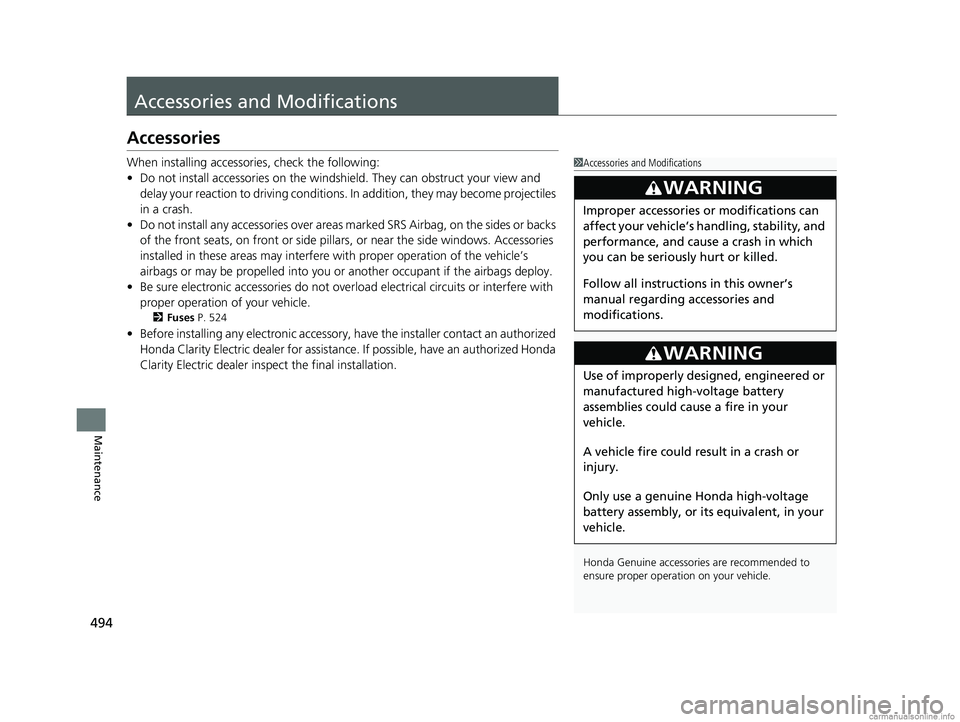
When installing accessories, check the following:
• Do not install accessories on the windshield. They can obstruct your view and
delay your reaction to driving conditions. In addition, they may become projectiles
in a crash.
• Do not install any accessorie s over areas marked SRS Airbag, on the sides or backs
of the front seats, on front or side pillars, or near the side windows. Accessories
installed in these areas may interfere with proper operation of the vehicle’s
airbags or may be propelled into you or another occupant if the airbags deploy.
• Be sure electronic accessories do not over load electrical circuits or interfere with
proper operation of your vehicle.
2 Fuses P. 524
•Before installing any electronic accessory, have the installer contact an authorized
Honda Clarity Electric dealer for assistance . If possible, have an authorized Honda
Clarity Electric dealer inspect the final installation.
1 Accessories and Modifications
Honda Genuine accessor ies are recommended to
ensure proper operati on on your vehicle.
3WARNING
Improper accessories or modifications can
affect your vehicle’s handling, stability, and
performance, and cause a crash in which
you can be seriously hurt or killed.
Follow all instruction s in this owner’s
manual regarding accessories and
modifications.
3WARNING
Use of improperly designed, engineered or
manufactured high-voltage battery
assemblies could cause a fire in your
vehicle.
A vehicle fire could result in a crash or
injury.
Only use a genuine Honda high-voltage
battery assembly, or it s equivalent, in your
vehicle.
18 CLARITY ELECTRIC CSS-31TRV6100.book 494 ページ 2018年2月5日 月曜日 午後12時0分
Page 499 of 559
497
Handling the Unexpected
This chapter explains how to handle unexpected troubles.
If a Tire Goes FlatTemporarily Repairi ng a Flat Tire....... 498
Handling of the Jack ......................... 510
Power System Won’t Start Checking the Procedure ................... 511
If the Smart Entry Remote Battery is Weak .......................................... 512
Emergency Power System Off........... 513
Jump Starting .................................... 514
Overheating How to Handle Overheating ............. 517 Indicator, Coming On/Blinking
If the 12-Volt Battery Charging System Indicator Comes On ....................... 518
If the Brake System Indicator (Red) Comes On or Blinks ....................................... 519
If the Electric Power Steering (EPS) System
Indicator Comes On ........................... 520If the Brake System Indicator (Red) Comes On or Blinks at the Same Time
When the Brake System Indicator
(Amber) Comes On ...................... 521
If the Low Tire Pressure/TPMS Indicator
Comes On or Blinks........................ 522 If the Transmission System Indicator Blinks
along with the Warning Message .... 523
Fuses
Fuse Locations ................................. 524
Inspecting and Changing Fuses ........ 530
Emergency Towing ........................... 531
When You Cannot Open the Charge
Lid ................................................. 532
When You Cannot Disengage the Charging
Connector.................................................533When You Cannot Open the Trunk .. 534
18 CLARITY ELECTRIC CSS-31TRV6100.book 497 ページ 2018年2月5日 月曜日 午後12時0分
Page 513 of 559
511
Handling the Unexpected
Power System Won’t Start
Checking the Procedure
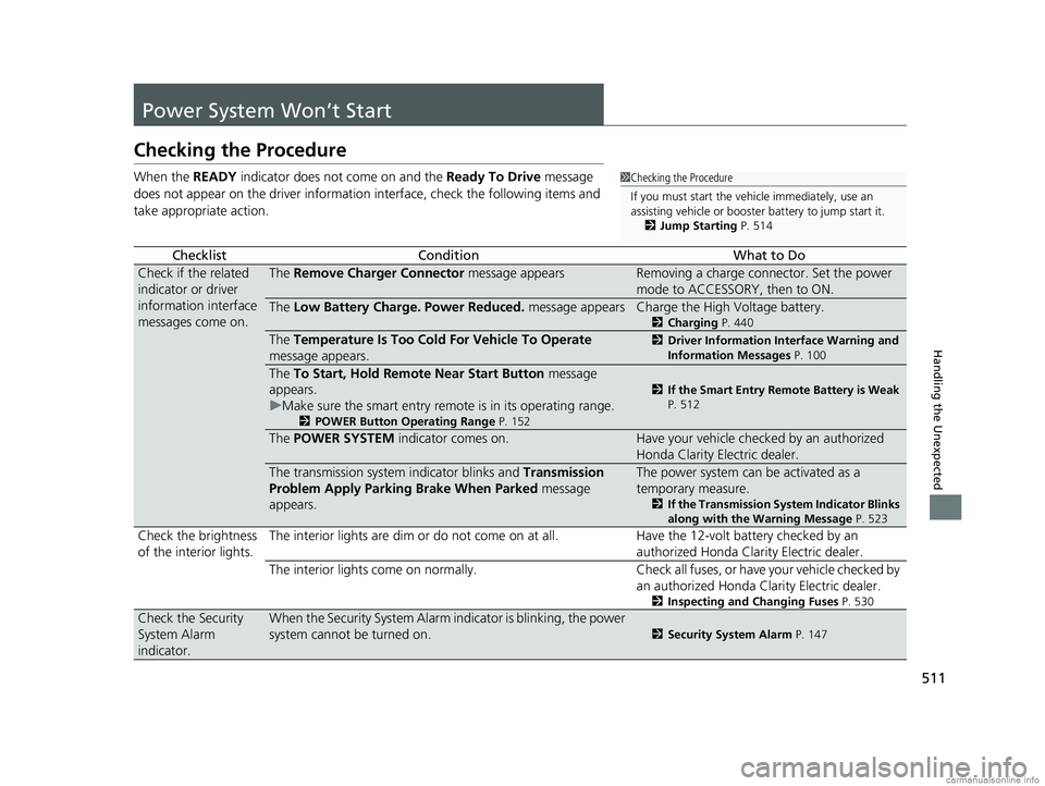
When the READY indicator does not come on and the Ready To Drive message
does not appear on the driver informatio n interface, check the following items and
take appropriate action.
ChecklistConditionWhat to Do
Check if the related
indicator or driver
information interface
messages come on.The Remove Charger Connector message appearsRemoving a charge connector. Set the power
mode to ACCESSORY, then to ON.
The Low Battery Charge . Power Reduced. message appearsCharge the High Voltage battery.
2Charging P. 440
The Temperature Is Too Cold For Vehicle To Operate
message appears.2 Driver Information Interface Warning and
Information Messages P. 100
The To Start, Hold Remote Near Start Button message
appears.
u Make sure the smart entry remote is in its operating range.
2 POWER Button Operating Range P. 152
2If the Smart Entry Remote Battery is Weak
P. 512
The POWER SYSTEM indicator comes on.Have your vehicle checked by an authorized
Honda Clarity Electric dealer.
The transmission system indicator blinks and Transmission
Problem Apply Parking Brake When Parked message
appears.The power system can be activated as a
temporary measure.
2 If the Transmission System Indicator Blinks
along with the Warning Message P. 523
Check the brightness
of the interior lights. The interior lights are dim or do not come on at
all. Have the 12-volt battery checked by an
authorized Honda Clarity Electric dealer.
The interior lights come on normally. Check all fuses, or have your vehicle checked by an authorized Honda Clarity Electric dealer.
2Inspecting and Changing Fuses P. 530
Check the Security
System Alarm
indicator.When the Security System Alarm in dicator is blinking, the power
system cannot be turned on.
2 Security System Alarm P. 147
1Checking the Procedure
If you must start the vehi cle immediately, use an
assisting vehicle or booster battery to jump start it.
2 Jump Starting P. 514
18 CLARITY ELECTRIC CSS-31TRV6100.book 511 ページ 2018年2月5日 月曜日 午後12時0分
Page 526 of 559
524
Handling the Unexpected
Fuses
Fuse Locations
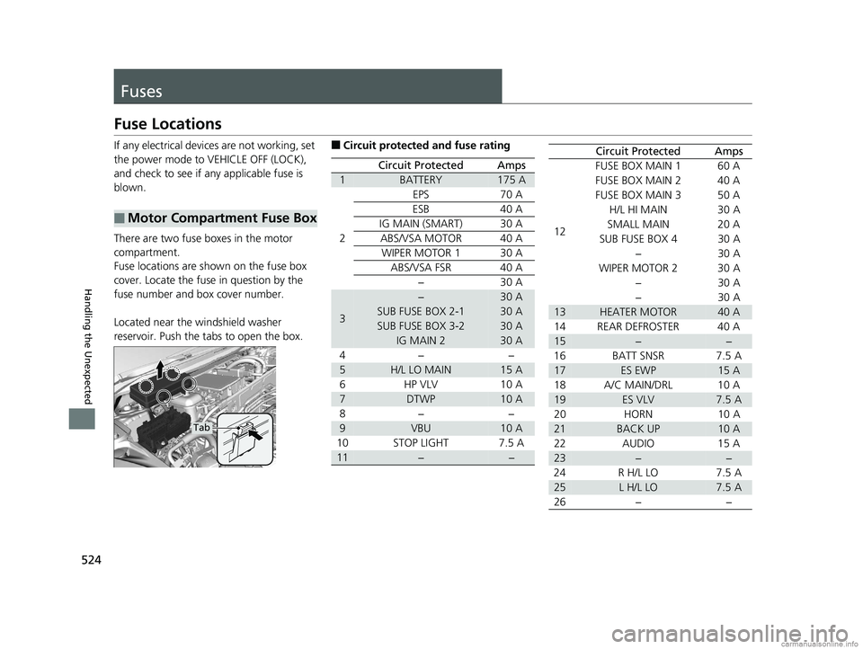
If any electrical devices are not working, set
the power mode to VEHICLE OFF (LOCK),
and check to see if any applicable fuse is
blown.
There are two fuse boxes in the motor
compartment.
Fuse locations are shown on the fuse box
cover. Locate the fuse in question by the
fuse number and box cover number.
Located near the windshield washer
reservoir. Push the tabs to open the box.
■Motor Compartment Fuse Box
Tab
■Circuit protected and fuse rating
Circuit ProtectedAmps
1BATTERY175 A
2
EPS70 A
ESB40 A
IG MAIN (SMART)30 A
ABS/VSA MOTOR40 A
WIPER MOTOR 130 A
ABS/VSA FSR40 A
−30 A
3
−30 A
SUB FUSE BOX 2-130 A
SUB FUSE BOX 3-230 A
IG MAIN 230 A
4− −
5H/L LO MAIN15 A
6HP VLV 10 A
7DTWP10 A
8− −
9VBU10 A
10 STOP LIGHT 7.5 A
11−−
Circuit ProtectedAmps
12 FUSE BOX MAIN 1 60 A
FUSE BOX MAIN 2 40 A
FUSE BOX MAIN 3 50 A
H/L HI MAIN 30 A
SMALL MAIN 20 A
SUB FUSE BOX 4 30 A − 30 A
WIPER MOTOR 2 30 A − 30 A
− 30 A
13HEATER MOTOR40 A
14 REAR DEFROSTER 40 A
15−−
16 BATT SNSR 7.5 A
17ES EWP15 A
18 A/C MAIN/DRL 10 A
19ES VLV7.5 A
20 HORN 10 A
21BACK UP10 A
22 AUDIO 15 A
23−−
24 R H/L LO 7.5 A
25L H/L LO7.5 A
26 − −
18 CLARITY ELECTRIC CSS-31TRV6100.book 524 ページ 2018年2月5日 月曜日 午後12時0分
Page 527 of 559
525
uuFuses uFuse Locations
Continued
Handling the Unexpected
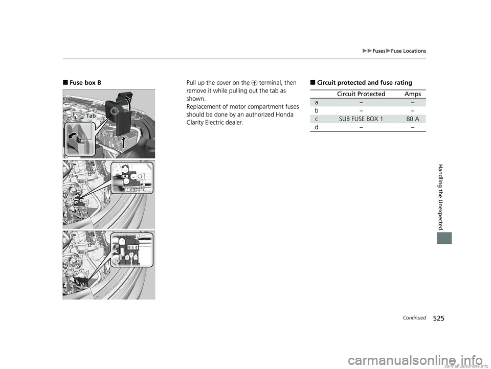
■Fuse box B
Tab
Pull up the cover on the + terminal, then
remove it while pulling out the tab as
shown.
Replacement of motor compartment fuses
should be done by an authorized Honda
Clarity Electric dealer.■Circuit protected and fuse rating
Circuit ProtectedAmps
a––
b––
cSUB FUSE BOX 180 A
d– –
18 CLARITY ELECTRIC CSS-31TRV6100.book 525 ページ 2018年2月5日 月曜日 午後12時0分
Page 528 of 559
526
uuFuses uFuse Locations
Handling the Unexpected
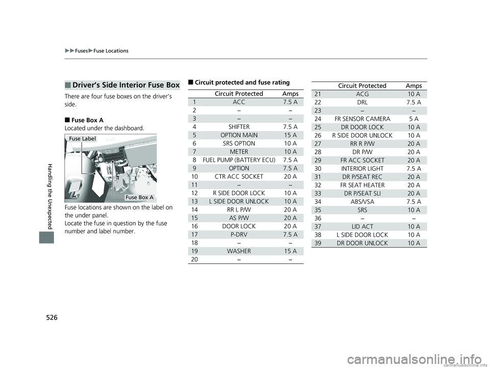
There are four fuse boxes on the driver’s
side.
■Fuse Box A
Located under the dashboard.
Fuse locations are shown on the label on
the under panel.
Locate the fuse in question by the fuse
number and label number.
■Driver’s Side Interior Fuse Box
Fuse Label
Fuse Box A
■Circuit protected and fuse rating
Circuit ProtectedAmps
1ACC7.5 A
2−−
3−−
4SHIFTER7.5 A
5OPTION MAIN15 A
6SRS OPTION10 A
7METER10 A
8FUEL PUMP (BATTERY ECU)7.5 A
9OPTION7.5 A
10CTR ACC SOCKET20 A
11−−
12R SIDE DOOR LOCK10 A
13L SIDE DOOR UNLOCK10 A
14RR L P/W20 A
15AS P/W20 A
16DOOR LOCK20 A
17P-DRV7.5 A
18−−
19WASHER15 A
20−−
Circuit ProtectedAmps
21ACG10 A
22DRL7.5 A
23−−
24FR SENSOR CAMERA5 A
25DR DOOR LOCK10 A
26R SIDE DOOR UNLOCK10 A
27RR R P/W20 A
28DR P/W20 A
29FR ACC SOCKET20 A
30INTERIOR LIGHT7.5 A
31DR P/SEAT REC20 A
32FR SEAT HEATER20 A
33DR P/SEAT SLI20 A
34ABS/VSA7.5 A
35SRS10 A
36−−
37LID ACT10 A
38L SIDE DOOR LOCK10 A
39DR DOOR UNLOCK10 A
18 CLARITY ELECTRIC CSS-31TRV6100.book 526 ページ 2018年2月5日 月曜日 午後12時0分
Page 529 of 559
527
uuFuses uFuse Locations
Continued
Handling the Unexpected
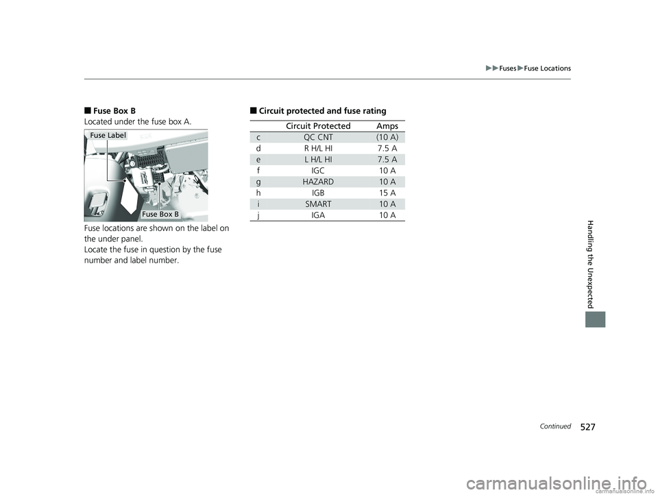
■Fuse Box B
Located under the fuse box A.
Fuse locations are shown on the label on
the under panel.
Locate the fuse in question by the fuse
number and label number.
Fuse Label
Fuse Box B
■Circuit protected and fuse rating
Circuit ProtectedAmps
cQC CNT(10 A)
dR H/L HI7.5 A
eL H/L HI7.5 A
fIGC10 A
gHAZARD10 A
hIGB15 A
iSMART10 A
jIGA10 A
18 CLARITY ELECTRIC CSS-31TRV6100.book 527 ページ 2018年2月5日 月曜日 午後12時0分
Page 530 of 559
528
uuFuses uFuse Locations
Handling the Unexpected
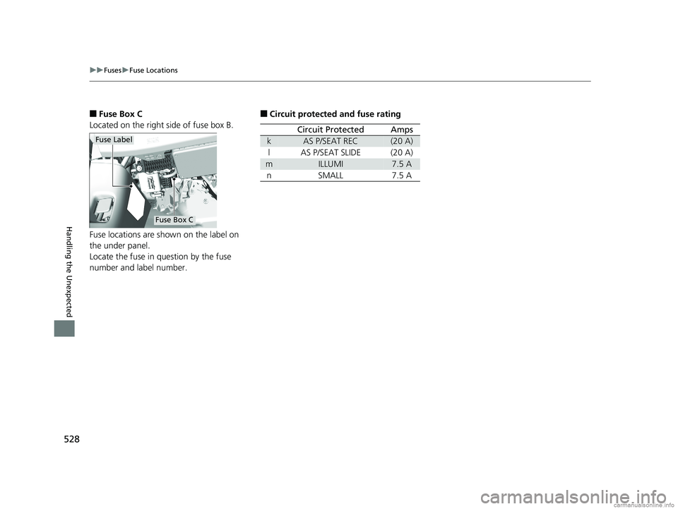
■Fuse Box C
Located on the right side of fuse box B.
Fuse locations are shown on the label on
the under panel.
Locate the fuse in question by the fuse
number and label number.
Fuse Label
Fuse Box C
■Circuit protected and fuse rating
Circuit ProtectedAmps
kAS P/SEAT REC(20 A)
lAS P/SEAT SLIDE(20 A)
mILLUMI7.5 A
nSMALL7.5 A
18 CLARITY ELECTRIC CSS-31TRV6100.book 528 ページ 2018年2月5日 月曜日 午後12時0分
Page 531 of 559
529
uuFuses uFuse Locations
Handling the Unexpected
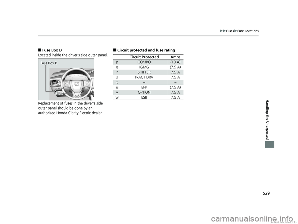
■Fuse Box D
Located inside the driver’s side outer panel.
Replacement of fuses in the driver’s side
outer panel should be done by an
authorized Honda Clarity Electric dealer.
Fuse Box D
■Circuit protected and fuse rating
Circuit ProtectedAmps
pCOMBO(10 A)
qIGMG(7.5 A)
rSHIFTER7.5 A
sP-ACT DRV7.5 A
t−−
uEPP(7.5 A)
vOPTION7.5 A
wESB7.5 A
18 CLARITY ELECTRIC CSS-31TRV6100.book 529 ページ 2018年2月5日 月曜日 午後12時0分