wheel HONDA CLARITY FUEL CELL 2018 (in English) Repair Manual
[x] Cancel search | Manufacturer: HONDA, Model Year: 2018, Model line: CLARITY FUEL CELL, Model: HONDA CLARITY FUEL CELL 2018Pages: 551, PDF Size: 27.22 MB
Page 432 of 551
430
uuBraking uAnti-lock Brake System (ABS)
Driving
Anti-lock Brake System (ABS)
Helps prevent the wheels from locking up, a nd helps you retain steering control by
pumping the brakes rapidly, much faster than you.
The electronic brake distribution (EBD) system, which is part of the ABS, also
balances the front-to-rear braking distri bution according to vehicle loading.
You should never pump the brake pedal. Let the ABS work for you by always
keeping firm, steady pressure on the brake pe dal. This is sometimes referred to as
“stomp and steer.”
■ABS operation
You may hear an operating noise when the ABS is working. Keep holding the pedal
firmly down. On dry pavement, you will need to press on the brake pedal very hard
before the ABS activates. However, you may feel the ABS activate immediately if you
are trying to stop on snow or ice.
ABS may activate when you depress the brake pedal when driving on:
• Wet or snow covered roads.
• Roads paved with stone.
• Roads with uneven surfaces, such as potholes, cracks, manholes, etc.
When the vehicle speed goes unde r 6 mph (10 km/h), the ABS stops.
■ABS1Anti-lock Brake System (ABS)
NOTICE
The ABS may not function correc tly if you use a tire of
the wrong size or type.
If the ABS indicator comes on while driving, there
may be a problem with the system.
While normal braking will not be affected, there is a
possibility that the ABS wi ll not be operating. Have
your vehicle checked by an authorized Honda Clarity
Fuel Cell dealer immediately.
The ABS is not designed for the purpose of reducing
the time or distance it takes for a vehicle to stop: It is
designed to limit brake lo ckup which can lead to
skidding and loss of steering control.
In the following cases, yo ur vehicle may need more
distance to stop than a vehicle without the ABS:
•You are driving on rough or uneven road surfaces,
such as gravel or snow.
•The tires are equipped with tire chains.
The following may be observed with the ABS system:
•Motor sounds coming from the motor
compartment when the brakes are applied, or
when system checks are being performed after the
power system has been turned on and while
vehicle accelerates.
•Brake pedal and/or the ve hicle body vibration when
ABS activates.
These vibrations and sounds are normal to ABS
systems and are no cause for concern.
18 CLARITY FUEL CELL PPO-31TRT6100.book 430 ページ 2017年11月21日 火曜日 午後3時3分
Page 434 of 551
432
uuBraking uCollision Mitigation Braking SystemTM (CMBSTM)
Driving
Collision Mitigati on Braking SystemTM (CMBSTM)
Can assist you when there is a possibility of your vehicle colliding with a vehicle or a
pedestrian detected in front of yours. The CMBSTM is designed to alert you when a
potential collision is determined, as well as to reduce your vehicle speed to help
minimize collision severity when a collision is deemed unavoidable.
■How the system works
1 Collision Mitigation Braking SystemTM (CMBSTM)
Important Safety Reminder
The CMBS
TM is designed to reduce the severity of an
unavoidable collision. It do es not prevent a collision
nor stop the vehicle automati cally. It is still your
responsibility to operate the brake pedal and steering
wheel appropriately acco rding to the driving
conditions.
The CMBS
TM may not activate or may not detect a
vehicle in front of y our vehicle under certain
conditions: 2 CMBS
TM Conditions and Limitations P. 436
You can read about handling information for the
camera equipped with this system. 2 Front Sensor Camera P. 383
Be careful not to severely impact the radar sensor
cover.
1 How the system works
Rapid vibrations on the steering wheel alert you
when the your vehicle speed is between 19 and 62
mph (30 and 100 km/h) with an oncoming vehicle
detected in front of you.
When the CMBS
TM activates, it may automatically
apply the brake. It will be canceled when your vehicle
stops or a potential coll ision is not determined.
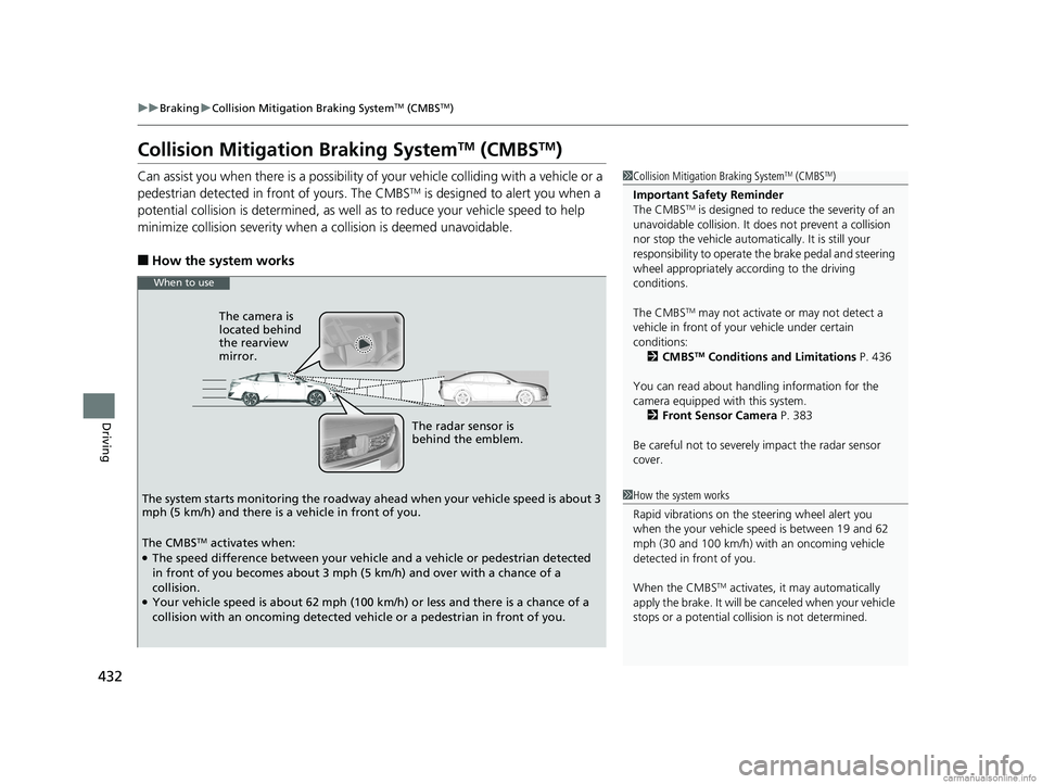
The radar sensor is
behind the emblem.
The camera is
located behind
the rearview
mirror.
The system starts monitoring the roadway ah ead when your vehicle speed is about 3
mph (5 km/h) and there is a vehicle in front of you.
When to use
The CMBSTM activates when:●The speed difference between your vehicle and a vehicle or pedestrian detected
in front of you becomes about 3 mph (5 km/h) and over with a chance of a
collision.
●Your vehicle speed is about 62 mph (100 km/h) or less and there is a chance of a
collision with an oncoming detected vehicle or a pedestrian in front of you.
18 CLARITY FUEL CELL PPO-31TRT6100.book 432 ページ 2017年11月21日 火曜日 午後3時3分
Page 435 of 551
Continued433
uuBraking uCollision Mitigation Braking SystemTM (CMBSTM)
Driving
■When the system activates
At system’s earliest collision alert st age, you can change the distance (Long/
Normal /Short ) between vehicles at which alerts will come on through audio/
information screen setting options.
2 Customized Features P. 300
■Vibration alert on the steering wheel
When a potential collision to an oncoming detected vehicle is determined, the
system alerts you with rapid vibration on the steering wheel, in addition to visual and
audible alerts. u Take appropriate action to prevent a col lision (apply the brakes, operate the
steering wheel, etc.).
1 When the system activates
The camera in the CMBS
TM is also designed to detect
pedestrians.
However, this pedestrian detection feature may not
activate or may not detect a pedestrian in front of
your vehicle under certain conditions.
Refer to the ones indicating the pedestrian detection
limitations from the list. 2 CMBS
TM Conditions and Limitations P. 436
The head-up warning uses a lens located at the front
end of the dashboard.
Do not cover the lens or spill any liquid on it.
Lens
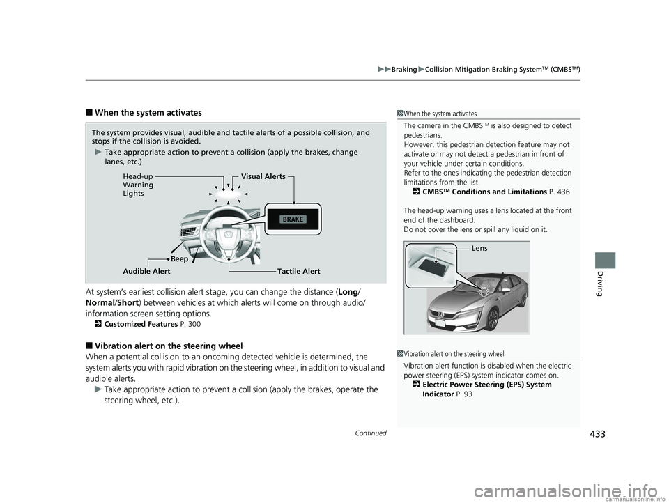
The system provides visual, audible and tactile alerts of a possible collision, and
stops if the collision is avoided.
u Take appropriate action to prevent a collision (apply the brakes, change
lanes, etc.)
Beep
Head-up
Warning
Lights
Visual Alerts
Audible Alert
Tactile Alert
1 Vibration alert on the steering wheel
Vibration alert function is disabled when the electric
power steering (EPS) system indicator comes on. 2 Electric Power Steering (EPS) System
Indicator P. 93
18 CLARITY FUEL CELL PPO-31TRT6100.book 433 ページ 2017年11月21日 火曜日 午後3時3分
Page 436 of 551
434
uuBraking uCollision Mitigation Braking SystemTM (CMBSTM)
Driving
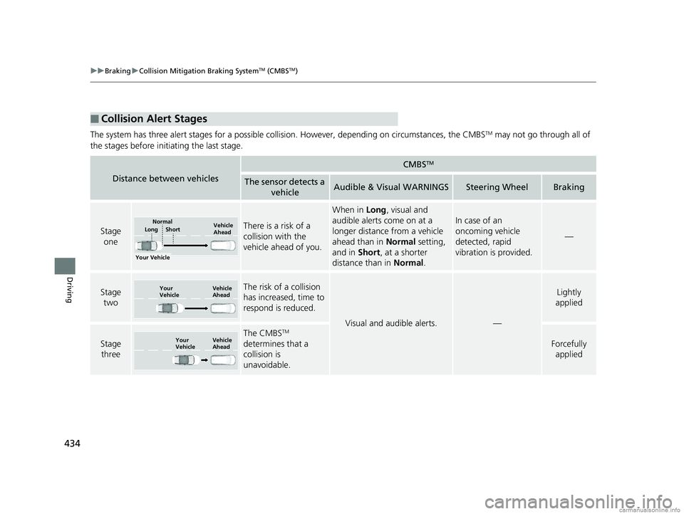
The system has three alert stages for a possible collis ion. However, depending on circumstances, the CMBSTM may not go through all of
the stages before initiating the last stage.
■Collision Alert Stages
Distance between vehicles
CMBSTM
The sensor detects a vehicleAudible & Visual WARNINGSSteering WheelBraking
Stage oneThere is a risk of a
collision with the
vehicle ahead of you.
When in Long, visual and
audible alerts come on at a
longer distance from a vehicle
ahead than in Normal setting,
and in Short, at a shorter
distance than in Normal.
In case of an
oncoming vehicle
detected, rapid
vibration is provided.
—
Stage
twoThe risk of a collision
has increased, time to
respond is reduced.
Visual and audible alerts.—
Lightly
applied
Stage three
The CMBSTM
determines that a
collision is
unavoidable.
Forcefully applied
Your Vehicle Vehicle
Ahead
Short
LongNormal
Your
Vehicle Vehicle
Ahead
Your
VehicleVehicle
Ahead
18 CLARITY FUEL CELL PPO-31TRT6100.book 434 ページ 2017年11月21日 火曜日 午後3時3分
Page 439 of 551
437
uuBraking uCollision Mitigation Braking SystemTM (CMBSTM)
Continued
Driving
■Vehicle conditions
• Headlight lenses are dirty or the h eadlights are not properly adjusted.
• The outside of the windshield is blocked by dirt, mud, leaves, wet snow, etc.
• The inside of the windshield is fogged.
• An abnormal tire or wheel condition (wrong sized, varied size or construction,
improperly inflated tire, etc.).
• When tire chains are installed.
• The vehicle is tilted due to a heavy load or suspension modifications.
• The camera temperature gets too high.
• Driving with the parking brake applied.
• When the radar sensor in the front grille gets dirty.
■Detection limitations
• A vehicle or pedestrian suddenly crosses in front of you.
• The distance between your vehicle and the vehicle or pedestrian ahead of you is
too short.
• A vehicle cuts in front of you at a slow speed, and it brakes suddenly.
• When you accelerate rapidly and approach the vehicle or pedestrian ahead of you
at high speed.
• The vehicle ahead of you is a motorcycle, bicycle, mobility scooter or other small
vehicle.
• When there are animals in front of your vehicle.
• When you drive on a curved, winding or und ulating road that makes it difficult for
the sensor to properly detect a vehicle in front of you.
• The speed difference between your vehicle an d a vehicle or pedestrian in front of
you is significantly large.
• An oncoming vehicle suddenly comes in front of you.
• Another vehicle suddenly comes in fr ont of you at an intersection, etc.
• Your vehicle abruptly crosses over in front of an oncoming vehicle.
• When driving through a narrow iron bridge.
• When the lead vehicle suddenly slows down.
18 CLARITY FUEL CELL PPO-31TRT6100.book 437 ページ 2017年11月21日 火曜日 午後3時3分
Page 443 of 551
441
uuParking Your Vehicle uWhen Stopped
Driving
Always confirm the electric parking brake is set, in particular if you are parked on an
incline.1When Stopped
In extremely cold temperatures, the parking brake
may freeze up if applied. If such temperatures are
expected, do not apply the parking brake but, if
parking on a slope, either turn the front wheels so
they will contact the curb if the vehicle rolls down the
slope or block the wheels to keep the vehicle from
moving. If you do not take either precaution, the
vehicle may roll unexpect edly, leading to a crash.
18 CLARITY FUEL CELL PPO-31TRT6100.book 441 ページ 2017年11月21日 火曜日 午後3時3分
Page 444 of 551
442
Driving
Multi-View Rear Camera
About Your Multi-View Rear Camera
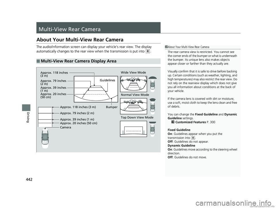
The audio/information screen can display your vehicle’s rear view. The display
automatically changes to the rear view when the transmission is put into
(R.
■Multi-View Rear Camera Display Area
1About Your Multi-View Rear Camera
The rear camera view is restricted. You cannot see
the corner ends of the bum per or what is underneath
the bumper. Its unique le ns also makes objects
appear closer or farther than they actually are.
Visually confirm that it is safe to drive before backing
up. Certain conditions (such as weather, lighting, and
high temperatures) may also restrict the rear view. Do
not rely on the rearview display which does not give
you all information about conditions at the back of
your vehicle.
If the camera lens is cove red with dirt or moisture,
use a soft, moist cloth to keep the lens clean and free
of debris.
You can change the Fixed Guideline and Dynamic
Guideline settings.
2 Customized Features P. 300
Fixed Guideline
On : Guidelines appear when you put the
transmission into
( R.
Off : Guidelines do not appear.
Dynamic Guideline
On : Guidelines move according to the steering wheel
direction.
Off : Guidelines do not move.
Top Down View Mode Normal View Mode Wide View Mode
Guidelines
Bumper
Camera Approx. 118 inches (3 m)
Approx. 79 inches (2 m)
Approx. 39 inches (1 m)
Approx. 20 inches (50 cm)
Approx. 118 inches
(3 m)
Approx. 79 inches
(2 m)
Approx. 39 inches
(1 m)
Approx. 20 inches
(50 cm)
18 CLARITY FUEL CELL PPO-31TRT6100.book 442 ページ 2017年11月21日 火曜日 午後3時3分
Page 451 of 551
449
Maintenance
This chapter discusses basic maintenance.
Before Performing MaintenanceInspection and Maintenance ............ 450
Safety When Performing Maintenance...451
Parts and Fluids Used in Maintenance Service ........................................... 452
Maintenance Minder
TM..................... 453
Maintenance Under the Hood Maintenance Items Under the Hood .. 457
Opening the Hood ........................... 458
Inverter Coolant ............................... 459
Transmission Fluid ............................ 461
Brake Fluid ....................................... 461 Refilling Window Wa
sher Fluid......... 462
Replacing Light Bulbs ....................... 463
Checking and Maintaining Wiper
Blades .......................................... 465
Checking and Maintaining Tires
Checking Tires ................................. 468
Tire and Loading Information Label .. 469
Tire Labeling .................................... 469
DOT Tire Quality Grading (U.S. Vehicles).. 471
Wear Indicators................................ 473
Tire Service Life ................................ 473
Tire and Wheel Replacement............ 474 Tire Rotation .................................... 475
Winter Tires ..................................... 476
12-Volt Battery ................................. 477
Remote Transmitter Care Replacing the Button Battery ........... 479
Climate Control System Maintenance.. 480
CleaningInterior Care .................................... 481
Exterior Care.................................... 483
Accessories and Modifications ........ 487
18 CLARITY FUEL CELL PPO-31TRT6100.book 449 ページ 2017年11月21日 火曜日 午後3時3分
Page 470 of 551
468
Maintenance
Checking and Maintaining Tires
Checking Tires
To safely operate your vehicle, your tires must be of the proper type and size, in
good condition with adequate tread, and properly inflated.
■Inflation guidelines
Properly inflated tires provide the best combination of handling, tread life, and comfort.
Refer to the driver’s doorjamb label or spec ifications page for the specified pressure.
Underinflated tires wear unevenly, adversely affect handling and fuel economy, and
are more likely to fail from overheating.
Overinflated tires make your vehicle ride harshly, are more prone to road hazards,
and wear unevenly.
Every day before you drive, look at each of the tires. If one looks lower than the
others, check the pressure with a tire gauge.
At least once a month or before long trips, use a gauge to measure the pressure in
all tires. Even tires in good condition ca n lose 1–2 psi (10–20 kPa, 0.1–0.2 kgf/cm
2)
per month.
■Inspection guidelines
Every time you check inflation, also examine the tires and valve stems.
Look for:
• Bumps or bulges on the side or in the tread. Replace the tire if you find any cuts,
splits, or cracks in the si de of the tire. Replace it if you see fabric or cord.
• Remove any foreign objects and inspect for air leaks.
• Uneven tread wear. Have an authorized Honda Clarity Fuel Cell dealer check the
wheel alignment.
• Excessive tread wear.
2 Wear Indicators P. 473
•Cracks or other damage around valve stem.
1Checking Tires
Measure the air pressure when tires are cold. This
means the vehicle has been parked for at least three
hours, or driven less than 1 mile (1.6 km). If
necessary, add or releas e air until the specified
pressure is reached.
If checked when hot, tire pressure can be as much as
4–6 psi (30–40 kPa, 0.3–0.4 kgf/cm
2) higher than if
checked when cold.
Whenever tire pressure is adjusted, you must
calibrate the TPMS. 2 TPMS Calibration P. 415
Have an authorized Honda Clarity Fuel Cell dealer
check the tires if you feel a consistent vibration while
driving. New tire s and any that have been removed
and reinstalled should be properly balanced.
3WARNING
Using tires that are excessively worn or
improperly inflated can cause a crash in
which you can be seriously hurt or killed.
Follow all instruction s in this owner’s
manual regarding ti re inflation and
maintenance.
18 CLARITY FUEL CELL PPO-31TRT6100.book 468 ページ 2017年11月21日 火曜日 午後3時3分
Page 474 of 551
uuChecking and Maintaining Tires uDOT Tire Quality Grading (U.S. Vehicles)
472
Maintenance
The traction grades, from highest to lowest, are AA, A, B, and C.
Those grades represent the tire’s ability to stop on wet pavement
as measured under controlled conditions on specified
government test surfaces of asphalt and concrete. A tire marked
C may have poor traction performance.
The temperature grades are A (the highest), B, and C,
representing the tire’s resistance to the generation of heat and its
ability to dissipate h eat when tested under controlled conditions
on a specified indoor laboratory test wheel. Sustained high
temperature can cause the material of the tire to degenerate and
reduce tire life, and excessive temp erature can lead to sudden tire
failure. The grade C corresponds to a level of performance which
all passenger car tires must meet under the Federal Motor Vehicle
Safety Standard No. 109. Grades B and A represent higher levels
of performance on the laboratory test wheel than the minimum
required by law.
■Traction
■Temperature
1 Traction
Warning: The traction grade
assigned to this tire is based on
straight-ahead braking traction tests,
and does not include acceleration,
cornering, hydroplaning, or peak
traction characteristics.
1Temperature
Warning: The temperature grade for
this tire is establishe d for a tire that is
properly inflated and not
overloaded. Excessive speed,
underinflation, or excessive loading,
either separately or in combination,
can cause heat buildup and possible
tire failure.
18 CLARITY FUEL CELL PPO-31TRT6100.book 472 ページ 2017年11月21日 火曜日 午後3時3分