fuses HONDA CLARITY PLUG IN HYBRID 2018 Owners Manual
[x] Cancel search | Manufacturer: HONDA, Model Year: 2018, Model line: CLARITY PLUG IN HYBRID, Model: HONDA CLARITY PLUG IN HYBRID 2018Pages: 591, PDF Size: 24.66 MB
Page 7 of 591
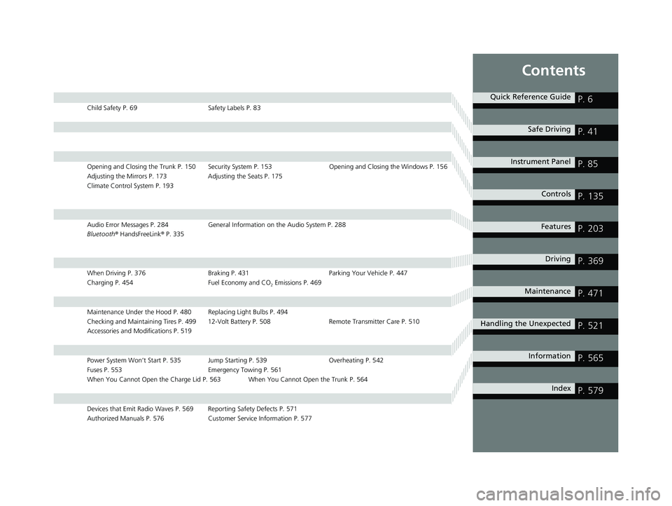
ContentsChild Safety P. 69 Safety Labels P. 83
Opening and Closing the Trunk P. 150 Security System P. 153 Opening and Closing the Windows P. 156
Adjusting the Mirrors P. 173 Adjusting the Seats P. 175
Climate Control System P. 193
Audio Error Messages P. 284 General Information on the Audio System P. 288
Bluetooth ® HandsFreeLink ® P. 335
When Driving P. 376 Braking P. 431 Parking Your Vehicle P. 447
Charging P. 454 Fuel Economy and CO 2
Emissions P. 469
Maintenance Under the Hood P. 480 Replacing Light Bulbs P. 494
Checking and Maintaining Tires P. 499 12-Volt Battery P. 508 Remote Transmitter Care P. 510
Accessories and Modifications P. 519
Power System Won’t Start P. 535 Jump Starting P. 539 Overheating P. 542
Fuses P. 553 Emergency Towing P. 561
When You Cannot Open the Charge Lid P. 563 When You Cannot Open the Trunk P. 564
Devices that Emit Radio Waves P. 569 Reporting Safety Defects P. 571
Authorized Manuals P. 576 Customer Service Information P. 577 Quick Reference Guide
P. 6 Safe Driving
P. 41 Instrument Panel
P. 85 Controls
P. 135 Features
P. 203 Driving
P. 369 Maintenance
P. 471 Handling the Unexpected
P. 521 Information
P. 565
Index
P. 57918 CLARITY PHEV CSS-31TRW6000.book 7 ページ 2017年8月31日 木曜日 午後2時4 9分
Page 521 of 591
519
Maintenance
Accessories and Modifications Accessories When installing accessori es, check the following:
• Do not install accessories on the windsh ield. They can obstruct your view and
delay your reaction to driving conditions.
• Do not install any accessories over areas marked SRS Airbag, on the sides or backs
of the front seats, on front or side pillars, or near the side windows. Accessories
installed in these areas may interfere wi th proper operation of the vehicle’s
airbags or may be propelled into you or another occupant if the airbags deploy.
• Be sure electronic accessories do not overload electrical circuits or interfere with
proper operation of your vehicle. 2 Fuses P. 553
• Before installing any electronic accessory, have the installer contact an authorized
Honda Clarity Plug-In Hybrid dealer for assi stance. If possible, have an authorized
Honda Clarity Plug-In Hybrid dealer inspect the final installation. 1 Accessories and Modifications
Honda Genuine accessor ies are recommended to
ensure proper operati on on your vehicle.3
WARNING Improper accessories or modifications can
affect your vehicle’s handling, stability, and
performance, and cause a crash in which
you can be seriously hurt or killed.
Follow all instruction s in this owner’s
manual regarding accessories and
modifications.
3
WARNING Use of improperly designed, engineered or
manufactured high-voltage battery
assemblies could cause a fire in your
vehicle.
A vehicle fire could result in a crash or
injury.
Only use a genuine Honda high-voltage
battery assembly, or it s equivalent, in your
vehicle.18 CLARITY PHEV CSS-31TRW6000.book 519 ページ 2017年8月31日 木曜日 午後2時49分
Page 523 of 591
521Handling the Unexpected This chapter explains how to handle unexpected troubles.
If a Tire Goes Flat
Temporarily Repairi ng a Flat Tire....... 522
Handling of the Jack ......................... 534
Power System Won’t Start
Checking the Procedure ................... 535
If the Smart Entry Remote Battery is
Weak .......................................... 537
Emergency Power System Off........... 538
Jump Starting .................................... 539
Overheating
How to Handle Overheating ............. 542
Indicator, Coming On/Blinking
If the Low Oil Pressure Warning Appears .. 545 If the 12-Volt Battery Charging System
Indicator Comes On ....................... 546
If the Malfunction Indicator Lamp Comes
On or Blinks ..................................... 547
If the Brake System Indicator (Red) Comes
On or Blinks ....................................... 548
If the Electric Power Steering (EPS) System
Indicator Comes On ........................... 549
If the Brake System Indicator (Red)
Comes On or Blinks at the Same Time
When the Brake System Indicator
(Amber) Comes On ...................... 550 If the Low Tire Pressure/TPMS Indicator
Comes On or Blinks ....................... 551
If the Transmission System Indicator Blinks
along with the Warning Message .... 552
Fuses
Fuse Locations ................................. 553
Inspecting and Changing Fuses ........ 560
Emergency Towing ........................... 561
When You Cannot Unlock the Fuel Fill
Door ................................................. 562
When You Cannot Open the Charge
Lid ................................................. 563
When You Cannot Open the Trunk .. 56418 CLARITY PHEV CSS-31TRW6000.book 521 ページ 2017年8月31日 木曜日 午後2時49分
Page 537 of 591
535Continued
Handling the Unexpected
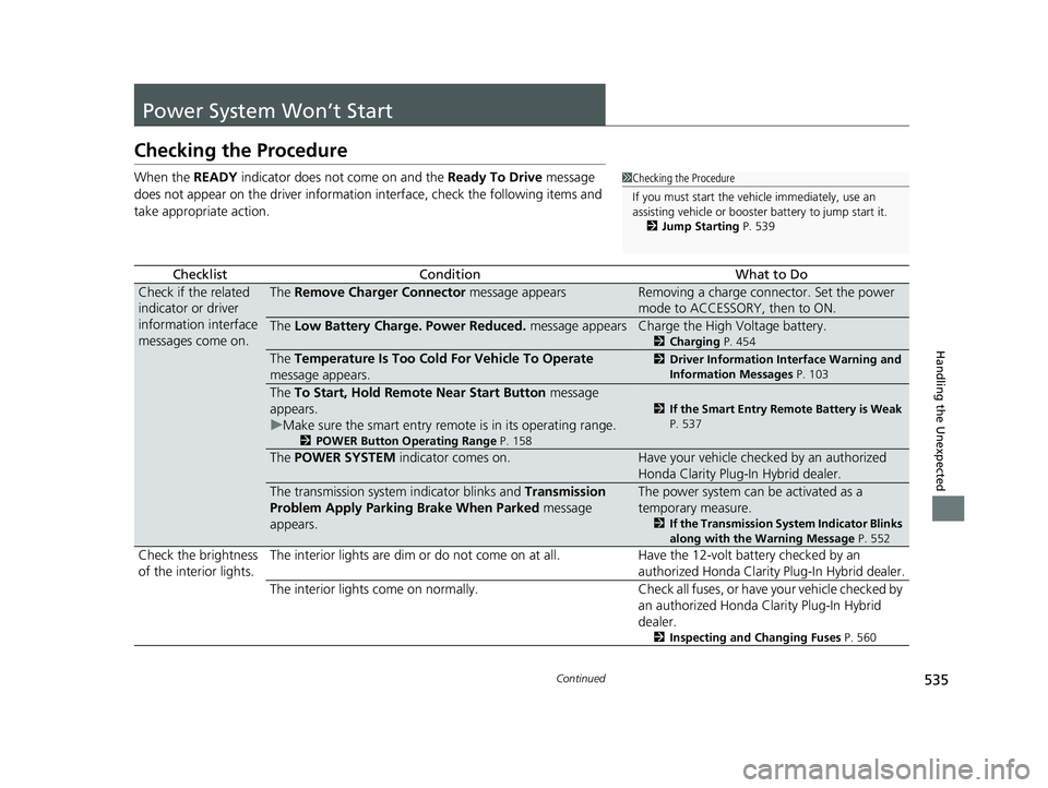
Power System Won’t Start Checking the Procedure When the READY indicator does not come on and the Ready To Drive message
does not appear on the driver informatio n interface, check the following items and
take appropriate action.
Checklist Condition What to Do
Check if the related
indicator or driver
information interface
messages come on. The Remove Charger Connector message appears Removing a charge connector. Set the power
mode to ACCESSORY, then to ON.
The Low Battery Charge . Power Reduced. message appears Charge the High Voltage battery. 2 Charging P. 454
The Temperature Is Too Cold For Vehicle To Operate
message appears. 2 Driver Information Interface Warning and
Information Messages P. 103
The To Start, Hold Remote Near Start Button message
appears.
u Make sure the smart entry remote is in its operating range. 2 POWER Button Operating Range P. 158 2 If the Smart Entry Remote Battery is Weak
P. 537
The POWER SYSTEM indicator comes on. Have your vehicle checked by an authorized
Honda Clarity Plug-In Hybrid dealer.
The transmission system indicator blinks and Transmission
Problem Apply Parking Brake When Parked message
appears. The power system can be activated as a
temporary measure. 2 If the Transmission System Indicator Blinks
along with the Warning Message P. 552
Check the brightness
of the interior lights. The interior lights are dim or do not come on at all. Have the 12-volt battery checked by an
authorized Honda Clarity Plug-In Hybrid dealer.
The interior lights come on normally. Check al l fuses, or have your vehicle checked by
an authorized Honda Clarity Plug-In Hybrid
dealer. 2 Inspecting and Changing Fuses P. 5601 Checking the Procedure
If you must start the vehi cle immediately, use an
assisting vehicle or booster battery to jump start it.
2 Jump Starting P. 53918 CLARITY PHEV CSS-31TRW6000.book 535 ページ 2017年8月31日 木曜日 午後2時49分
Page 555 of 591
553 Continued
Handling the Unexpected
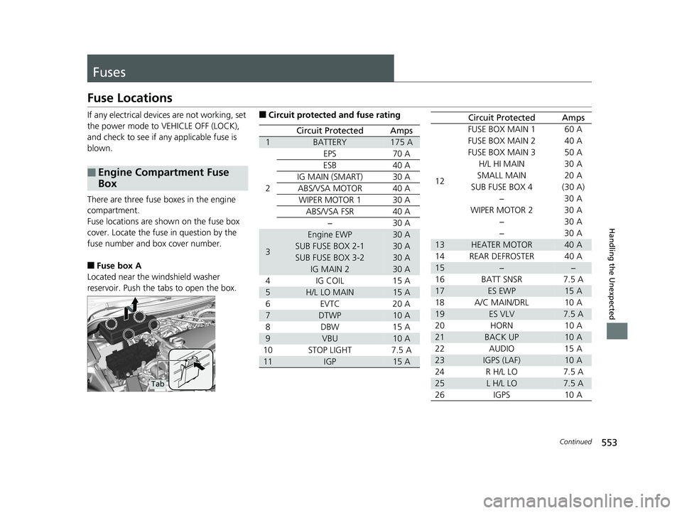
Fuses Fuse Locations If any electrical device s are not working, set
the power mode to VEHICLE OFF (LOCK),
and check to see if any applicable fuse is
blown.
There are three fuse boxes in the engine
compartment.
Fuse locations are shown on the fuse box
cover. Locate the fuse in question by the
fuse number and box cover number.
■ Fuse box A
Located near the windshield washer
reservoir. Push the tabs to open the box.■ Engine Compartment Fuse
Box
Tab ■ Circuit protected and fuse rating
Circuit Protected Amps
1 BATTERY 175 A
2 EPS 70 A
ESB 40 A
IG MAIN (SMART) 30 A
ABS/VSA MOTOR 40 A
WIPER MOTOR 1 30 A
ABS/VSA FSR 40 A
− 30 A
3 Engine EWP 30 A
SUB FUSE BOX 2-1 30 A
SUB FUSE BOX 3-2 30 A
IG MAIN 2 30 A
4 IG COIL 15 A
5 H/L LO MAIN 15 A
6EVTC 20 A
7 DTWP 10 A
8 DBW 15 A
9 VBU 10 A
10 STOP LIGHT 7.5 A
11 IGP 15 A 12 FUSE BOX MAIN 1 60 A
FUSE BOX MAIN 2 40 A
FUSE BOX MAIN 3 50 A
H/L HI MAIN 30 A
SMALL MAIN 20 A
SUB FUSE BOX 4 (30 A)
−30 A
WIPER MOTOR 2 30 A
−30 A
−30 A
13 HEATER MOTOR 40 A
14 REAR DEFROSTER 40 A
15 − −
16 BATT SNSR 7.5 A
17 ES EWP 15 A
18 A/C MAIN/DRL 10 A
19 ES VLV 7.5 A
20 HORN 10 A
21 BACK UP 10 A
22 AUDIO 15 A
23 IGPS (LAF) 10 A
24 R H/L LO 7.5 A
25 L H/L LO 7.5 A
26 IGPS 10 A Circuit Protected Amps18 CLARITY PHEV CSS-31TRW6000.book 553 ページ 2017年8月31日 木曜日 午後2時49分
Page 556 of 591
554 uu Fuses u Fuse Locations
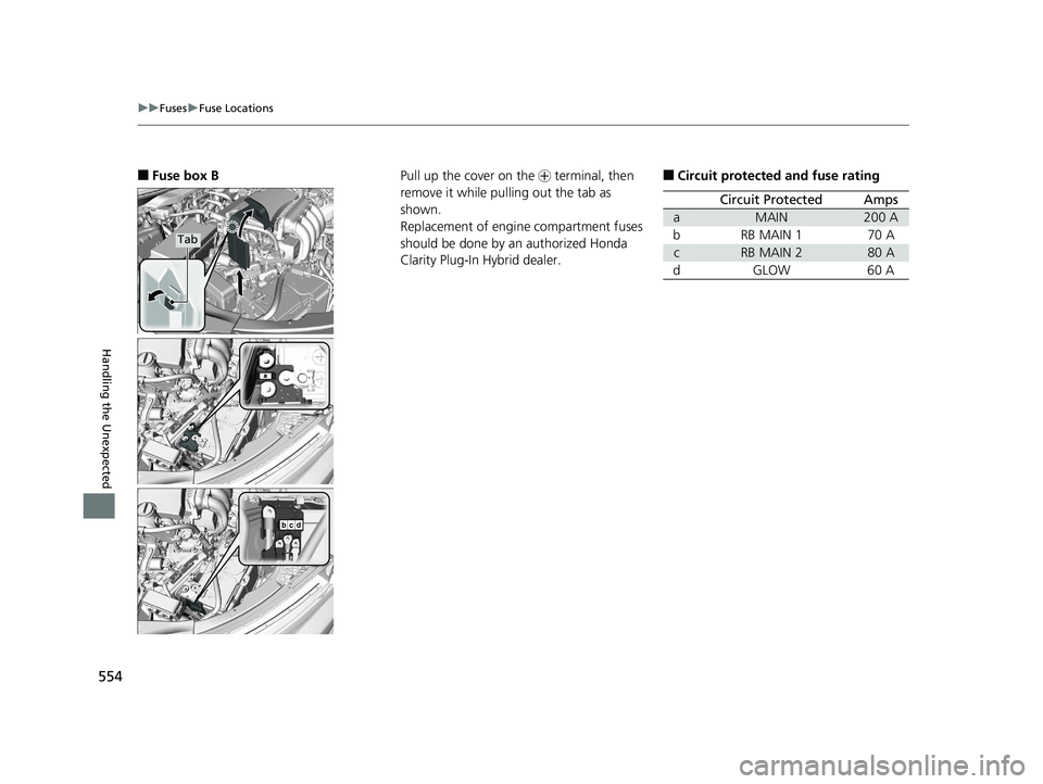
Handling the Unexpected ■ Fuse box B Tab
Pull up the cover on the + terminal, then
remove it while pulling out the tab as
shown.
Replacement of engine compartment fuses
should be done by an authorized Honda
Clarity Plug-In Hybrid dealer. ■ Circuit protected and fuse rating
Circuit Protected Amps
a MAIN 200 A
b RB MAIN 1 70 A
c RB MAIN 2 80 A
dGLOW 60 A18 CLARITY PHEV CSS-31TRW6000.book 554 ページ 2017年8月31日 木曜日 午後2時49分
Page 557 of 591
555 uu Fuses u Fuse Locations
Continued
Handling the Unexpected
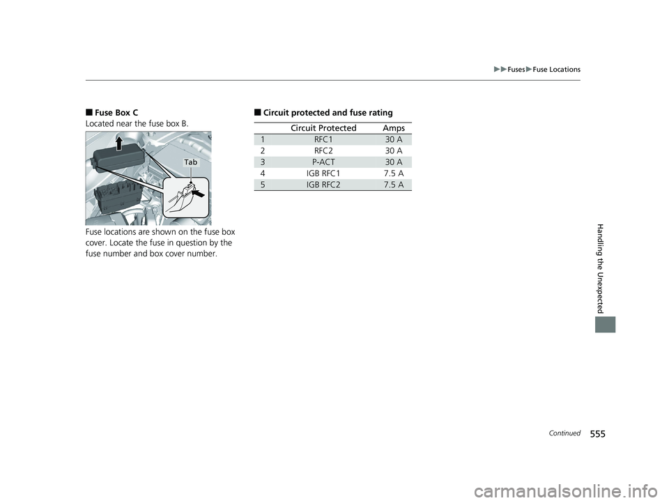
■ Fuse Box C
Located near the fuse box B.
Fuse locations are shown on the fuse box
cover. Locate the fuse in question by the
fuse number and box cover number. Tab
■ Circuit protected and fuse rating
Circuit Protected Amps
1 RFC1 30 A
2 RFC2 30 A
3 P-ACT 30 A
4 IGB RFC1 7.5 A
5 IGB RFC2 7.5 A18 CLARITY PHEV CSS-31TRW6000.book 555 ページ 2017年8月31日 木曜日 午後2時49分
Page 558 of 591
556 uu Fuses u Fuse Locations
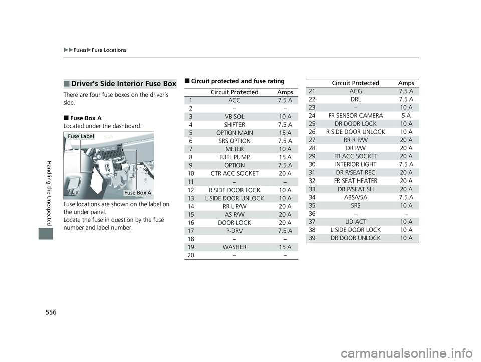
Handling the Unexpected There are four fuse boxes on the driver’s
side.
■ Fuse Box A
Located under the dashboard.
Fuse locations are shown on the label on
the under panel.
Locate the fuse in question by the fuse
number and label number.■ Driver’s Side Interior Fuse Box Fuse Label
Fuse Box A ■ Circuit protected and fuse rating
Circuit Protected Amps
1 ACC 7.5 A
2 − −
3 VB SOL 10 A
4 SHIFTER 7.5 A
5 OPTION MAIN 15 A
6 SRS OPTION 7.5 A
7 METER 10 A
8 FUEL PUMP 15 A
9 OPTION 7.5 A
10 CTR ACC SOCKET 20 A
11 − −
12 R SIDE DOOR LOCK 10 A
13 L SIDE DOOR UNLOCK 10 A
14 RR L P/W 20 A
15 AS P/W 20 A
16 DOOR LOCK 20 A
17 P-DRV 7.5 A
18 − −
19 WASHER 15 A
20 − − 21 ACG 7.5 A
22 DRL 7.5 A
23 − 10 A
24 FR SENSOR CAMERA 5A
25 DR DOOR LOCK 10 A
26 R SIDE DOOR UNLOCK 10 A
27 RR R P/W 20 A
28 DR P/W 20 A
29 FR ACC SOCKET 20 A
30 INTERIOR LIGHT 7.5 A
31 DR P/SEAT REC 20 A
32 FR SEAT HEATER 20 A
33 DR P/SEAT SLI 20 A
34 ABS/VSA 7.5 A
35 SRS 10 A
36 − −
37 LID ACT 10 A
38 L SIDE DOOR LOCK 10 A
39 DR DOOR UNLOCK 10 ACircuit Protected Amps18 CLARITY PHEV CSS-31TRW6000.book 556 ページ 2017年8月31日 木曜日 午後2時49分
Page 559 of 591
557 uu Fuses u Fuse Locations
Continued
Handling the Unexpected
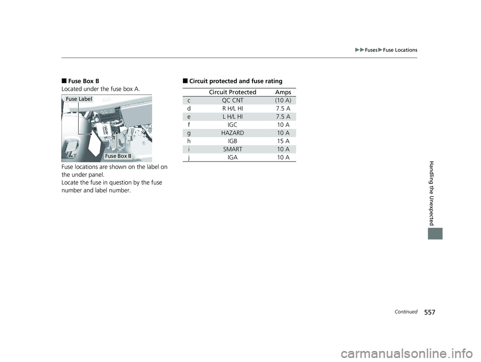
■ Fuse Box B
Located under the fuse box A.
Fuse locations are shown on the label on
the under panel.
Locate the fuse in question by the fuse
number and label number. Fuse Label
Fuse Box B ■ Circuit protected and fuse rating
Circuit Protected Amps
c QC CNT (10 A)
d R H/L HI 7.5 A
e L H/L HI 7.5 A
f IGC 10 A
g HAZARD 10 A
h IGB 15 A
i SMART 10 A
j IGA 10 A18 CLARITY PHEV CSS-31TRW6000.book 557 ページ 2017年8月31日 木曜日 午後2時49分
Page 560 of 591
558 uu Fuses u Fuse Locations
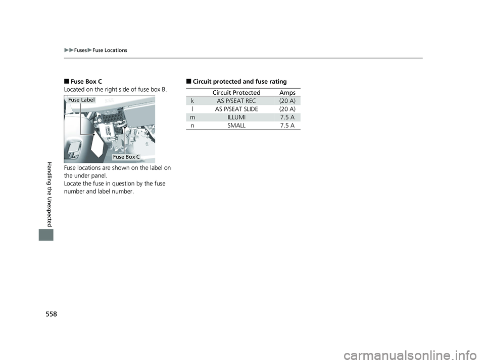
Handling the Unexpected ■ Fuse Box C
Located on the right side of fuse box B.
Fuse locations are shown on the label on
the under panel.
Locate the fuse in question by the fuse
number and label number. Fuse Label
Fuse Box C ■ Circuit protected and fuse rating
Circuit Protected Amps
k AS P/SEAT REC (20 A)
l AS P/SEAT SLIDE (20 A)
m ILLUMI 7.5 A
n SMALL 7.5 A18 CLARITY PHEV CSS-31TRW6000.book 558 ページ 2017年8月31日 木曜日 午後2時49分