voltage HONDA CR-V 1997 RD1-RD3 / 1.G Owners Manual
[x] Cancel search | Manufacturer: HONDA, Model Year: 1997, Model line: CR-V, Model: HONDA CR-V 1997 RD1-RD3 / 1.GPages: 1395, PDF Size: 35.62 MB
Page 414 of 1395
Emission Control System
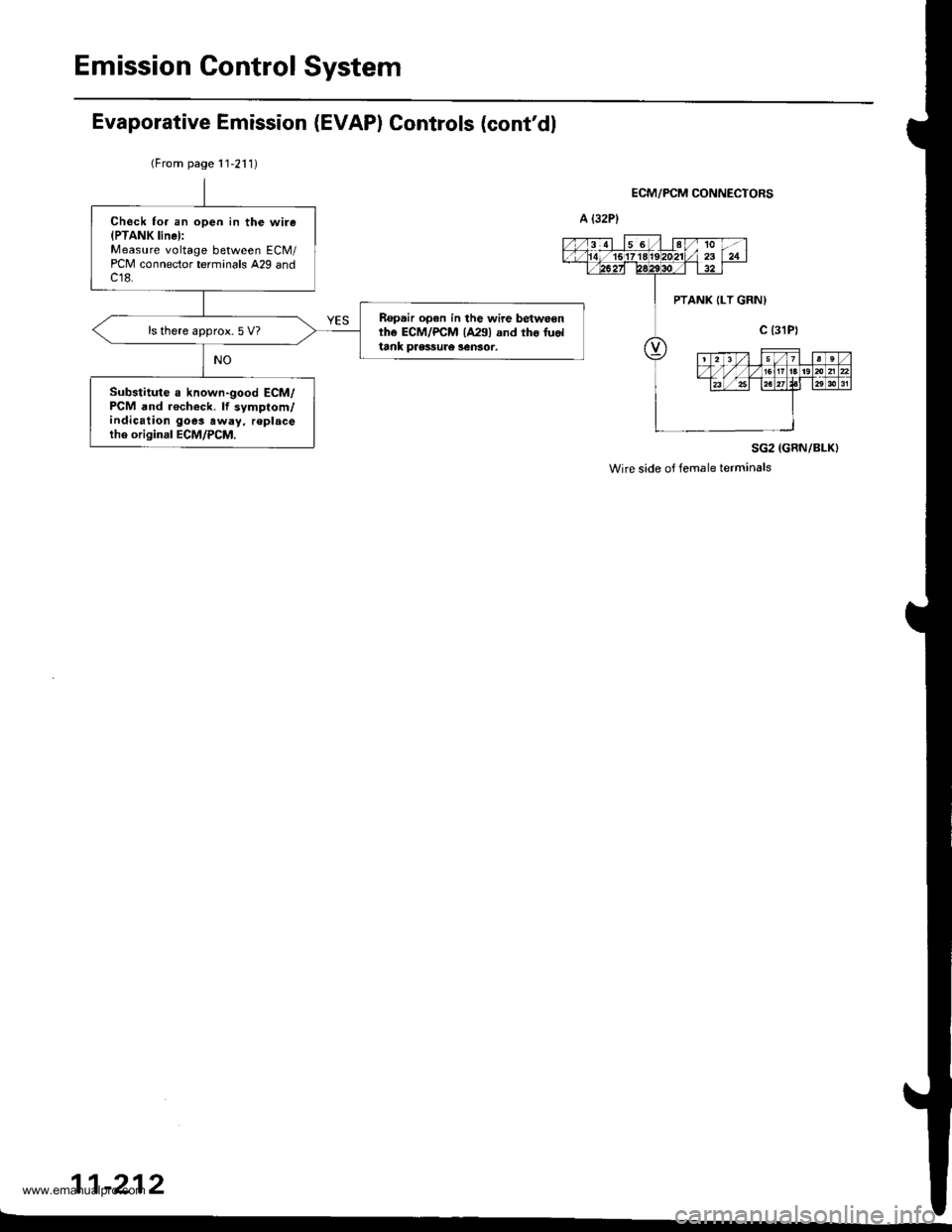
Check fo. an open in the wire(PTANK linel:Measure voltage between ECM/PCM connector terminals A29 andc18.
Ropair open in the wire betweonthe ECM/PCM {A291 and tho fuoltank pressule 3ensor.
ls there approx.5 V?
Substitute a known-good ECM/PCM and recheck. lf symptom/indication goes away, r€placetho originrl ECM/PCM.
Evaporative Emission (EVAP) Controls (cont'dl
(From page 11,211)
ECM/PCM CONNECTORS
SG2 (GRN/BLK}
Wire side of temale terminals
11-212
-
PTANK {LT GRNI
www.emanualpro.com
Page 416 of 1395
Emission Control System
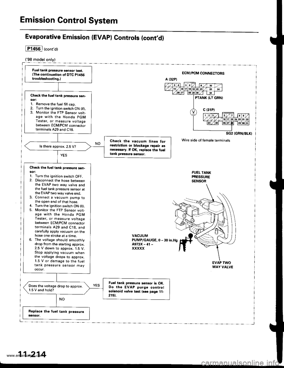
Fuel tank pros3ure sensor tost.(The continuetion of DTC Pl456t.oubls3hooting.,
Chock the tusl trnk pr€3sure sen-sor:1. Remove the fuel fill csp.2. Turn the ignition switch ON fll).3. Monitor the FTP Sensor voh-age with th€ Honda PGMTester, or measure voltagebetween ECM/PCM conn€ctorterminals A29 and C18.
Choct ths vacuum linsr forra3triction o. blockago ropair a!nect*rary. It OK, replaca the fu6ltank praituJc sentot.
ls there approx. 2.5 V?
Check the fuel t nk pressuae 3en-sor:1. Turn the ignition switch OFF.2. Disconnect the hose betweenthe EVAP two way valve andthe tueltank pressure sensor atthe EVAP two way valve end.3. Connect a vacuum pump tothe open end ofthat hose.4. Turn the ignition switch ON 0l).5. Monitor the FTP Sensor volt-age with the Honda PGMTestet, or measure voltagebetween ECM/PCM connectorterminals 429 and C18, andcarefully apply vacuum on thehose one stroke at a lime.6. The voltage should smoothtydrop from the staning approx.2.5 V down to approx. 1.5 V.Stop applying vacuum whenthe voltage drops to approx.1.5 V or damage to the fueltank pressure sensor fiayoccur,
Fu.l tank pressu.c a€nlor b OK.Oo thc EVAP pulge controlsolenoid valve toat (3€€ prgo 11-2151.
Does the voltage drop to approx.1.5 V and hold?
Evaporative Emission (EVAPI Controls (contd)
lP14s6l("ont,a)
ECM/PCM CONNECTORS
SG2 IGRN/BLKI
Wire side oI female terminals
FUEI- TANKPRESSURESENSOR
VACUUMPUMP/GAUGE,0 - 30 in.HgA973X - ill -
xxxxx
EVAP TWOWAY VALVE
11-214
www.emanualpro.com
Page 418 of 1395
Emission Control System
Evaporative Emission (EVAPI Controls (cont,dl
1T1456I (conro)
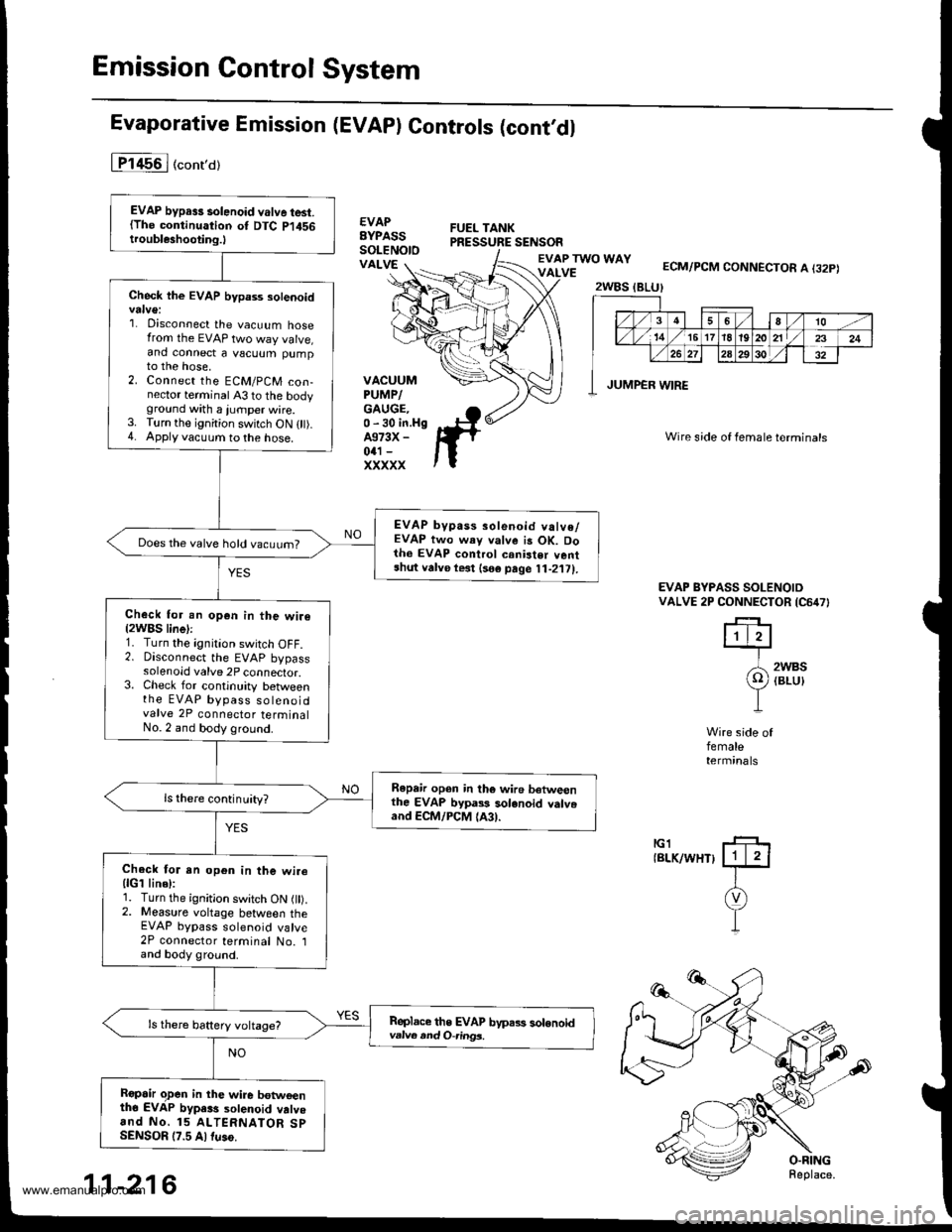
€VAPBYPASSSoLENOtOVALVEECM/PCM CONNECTOR A I32P)
Wire side of female terminals
VACUUMPUMP/GAUGE.0 -30 in.HgA373X -
041 -
xxxxx
EVAP BYPASS SOLENOIDVALVE 2P CONNECTOR lcorlTl
2WBS(BLU}
II
Wire side offemaletermrnats
tGlIBLK/WHT}
EVAP bypa3s solenoid valve test.(The continuation ot DTC P1456troubleshooting.l
Check the EVAP bypass sotenoid
1. Disconnect the vacuum hosefrom the EVAP two way valve,and connect a vscuum pumpto the hose,2. Connect the ECM/PCM con-nector terminal 43 to the bodyground with a jurnper wire.3. Turn the ignition switch ON 0t).4. Apply vacuum to the hose.
EVAP bypass solenoid valve/EVAP two way valve is OK. Doth6 EVAP control crnister ventshut vafve le3t lso€ page 11-2'111.
Does the valve hold vacuurn?
Check for an op€n in the wir€(2WBS line):1. Turn the ignition switch OFF.2. Disconnect the EVAP bypasssolenoid valve 2P connector.3. Check for continuity betweenthe EVAP bypass so teno idvalve 2P connector terminalNo. 2 and body ground.
Repair open in the wire betweenthe EVAP bypass solenoid valv.and ECM/PCM lA3).
Chack tor an op6n in the wirellcl line):1. Turn the ignition switch ON l).2. Measure voltage between theEVAP bypass solenoid valve2P connector terminal No. land body ground.
Replace the EVAP byps.,s solonoidvatus and O-ring3.
Ropair o,pen in the wire botwoenth6 EVAP bypa$ sotenoid vatvoand No. 15 ALTERNATOR SpSENSOR (7.5 Altuso.
2WBS (BLU}
/3
7,x
4l6o/to -/
,/ 16 1718't920 211/z3
26 272A29solT32
JUMPER WIRE
11-216
www.emanualpro.com
Page 422 of 1395
Emission Control System
Evaporative Emission (EVAP) Controls (cont,dl
iTl457l ("ont'or
APCONTROLCANISTER
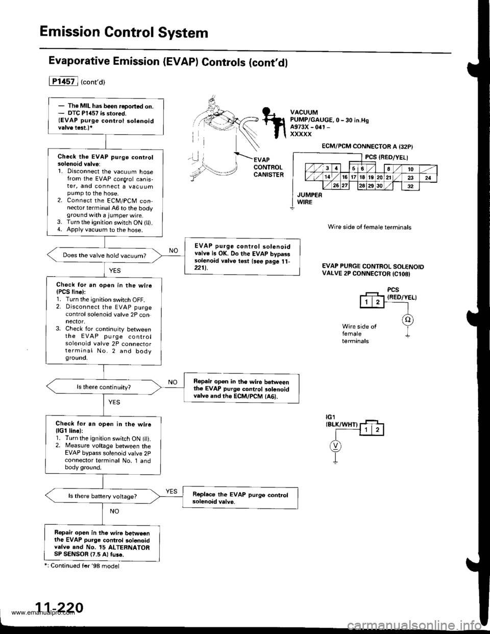
Ropair op€n in th6 wire betweenthe EVAP purge control 3olenoidvelve and ths ECM/PCM (A61.
VACUUMPUMP/GAUGE, O-30 iN.HgA973X - 0rl -
xxxxx
'\)
Wire side of lemale terminals
EVAP PURGE CONTROL SOI.ENOIDVALVE 2P CONNECTOR (Cl08)
PCSIRED/YELI
femaletermanals
ECM/PCM CONNECTOR A {32P}
PCS (RED/YELI
,/3 458/'t0
,,/ 14 ,/'t61718l92024
,/ 262930
JUMPERWIRE
- The MIL has been reported on.- DTC P1457 is stored.{EVAP purge control solenoidvalve test.l*
Check the EVAP purge conrrol30lenoid velve:L Disconnect the vacuum hosefrom the EVAP conlrol canis,ter, and connect a vacuumpump to the hose.2. Connect the ECM/PCM connector terminal A6 to the bodyground with a jumper wire.3. Turn the ignition switch ON (tl).4. Apply vacuum to the hose.
EVAP purge control solenoidvalve is OK. Oo the EVAP bypasssolenoid valve t€3t {see psge 1l-221t.
Does the valve hold vacuum?
Check for an open in the wire(PCS line):1. Turn the ignition switch OFF.2. Disconnect the EVAP purgecontrol solenoid valve 2P connector,3. Check for continuity betweenthe EVAP pu rge controlsolenoid valve 2P connectorterminal No.2 and bodygrouno,
ls there continuity?
Check for an open in the wire(lGl line):1. Turn the ignition switch ON t).2. Measure voltage between theEVAP bypass solenoid valve 2pcoonector terminal No. 1 andbody ground.
ls there battery voltage?
Repah open in lhe wir6 betwoenthe EVAP pu.ge cont.ol solonoidvdlvo and No. 15 ALTERNATORSP SENSOR {7.5 Al fu!€.
*: Continued frr '98 model
1-220
www.emanualpro.com
Page 424 of 1395
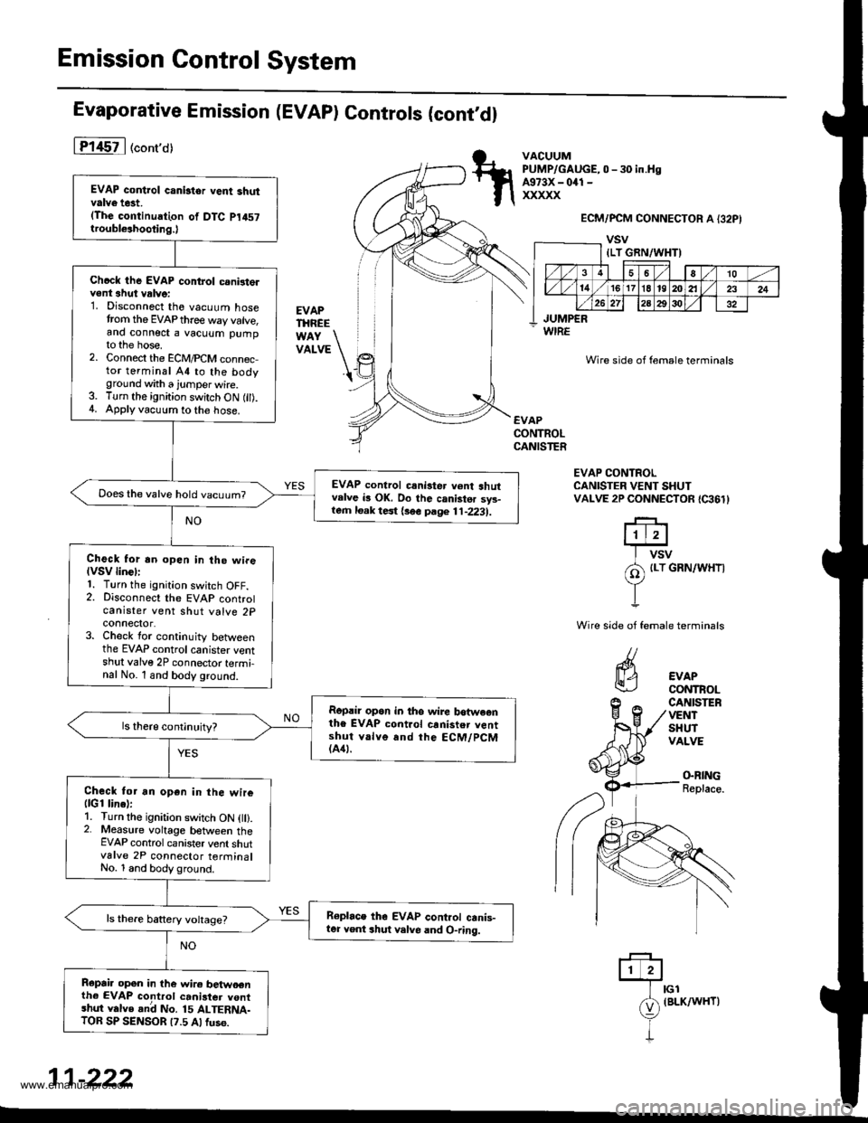
Emission Control System
Evaporative Emission (EVAP) Controls (cont,dl
lT145il ("ont'o)
EVAPTHREE
VATVE \'t
VACUUMPUMP/GAUGE,0 - 30 in.HsA973X - 041 -
xxxxx
WIRE
ECM/PCM CONNECTOR A {32PI
vsv
Wire side of female terminals
EVAPCONTROLCANISTER
EVAP CONTROLCANISTER VENT SHUTVALVE 2P CONNECTOR {C361}
riErr+J
I vsv
/A {Lr GRN/WHT|
YI
Wire side of female terminals
CANISTEFVENTSHUTVALVE
EVAPCONTROL
(}BING
Replace.
ffilrcr
e
(BLK/wHr)
I
11-222
EVAP control canistor vent shutvalve t6t.(The continuation of DTC p1457
troubl€ahooting.)
Chcck the EVAP control c.nirt6lvent ahut vrlve:1. Disconnect the vacuum hosetrom the EVAP thre€ way valve,and connect a vacuum pumpto the hose.2. Connect the ECM,PCM conn6c,tor terminal A4 to the bodyground with a jumper wire.3. Turn the ignition switch ON fil).4. Applyvacuum to the hose.
EVAP control crni3ter v6nt shutvelve b OK. Do the canistsr sys-lern loak test {3ee page 11-2231.
Does the valve hold vacuum?
Check for an open in the wireIVSV linGll1. Turn the ignition swjtch OFF.2. Disconnect the EVAP controlcanister vent shut valve 2pconnector.3. Check for continuity betweenthe EVAP control canister ventshul valve 2P connector termi-nal No. l and body ground.
Ropril op6n in tho wire botweonthe EVAP control canister v6ntshut v.lve and the ECM/PCM(A41.
Check tor an open in the wire(lGl line):1. Turn the ignition switch ON l).2. Measure voltage between theEVAP control canister vent shutvalve 2P connector terrninalNo. 1 and body ground.
Roplace thG EVAP cont.ol canis-ter Yent shut velve and O-ring.
Repai. opon in the wire betwoenth6 EVAP control canister vontshut valve .nd No. 15 ALTERNA-TOB SP SENSOR t?.5 Alfus6.
{LT GRN/WHT)
36a10
l4/1617l8't9202l232426 272a2930
JUMPER
www.emanualpro.com
Page 425 of 1395
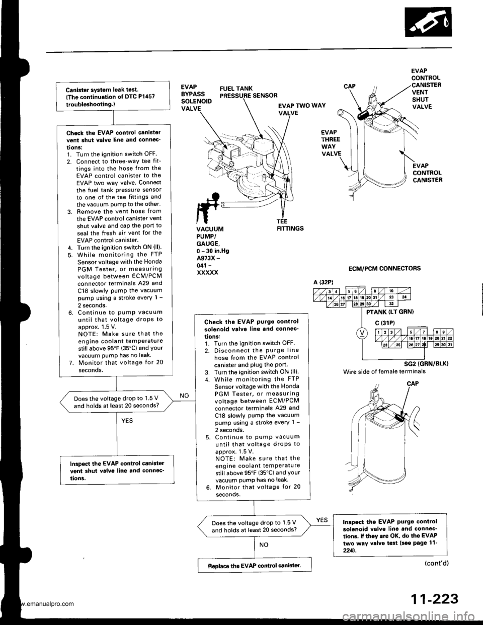
Canbter system leak test
{The continuation of DTC P1457
trouble3hootin9.)
Chock the EVAP control canistervent shut valve line and connoc'
tonS:1. Turn the ignition switch OFF
2. Connect to three'way tee fit_
tings into the hose from the
EVAP control canister to the
EVAP two way valve. Connect
the fuel tank pressure sensor
to one of the tee fittings and
the vacuum PumP to the other'
3. Remove the vent hose from
the EVAP control canister vent
shut valve and cap the Pon to
seal the fresh air vent Ior the
EVAP control canister.4. Turn the ignition switch ON (ll).
5. While monitoring the FTP
Sensor voltage with the Honda
PGM Tester, or measurangvoltage between ECM/PCM
connector terminals A29 and
C18 slowly PumP the vacuumpump using a stroke every 1 -
2 seconds.6. Continue to PumP vacuum
until that voltage droPs to
approx. 1.5 V.NOTE: Make sure that the
engine coolant temPeraturestillabove 95'F (35'Cland Yourvacuum PumP has no leak
7. Monitor that voltage for 20
seconds.
Check the EVAP Pu.ge control
solenoid valve line and connec-
tions:1. Turn the ignition switch OFF.
2. Disconnect the Purge lane
hose from the EVAP control
canister and Plug the Port3. Turn the ignition switch ON (lli.
4. While monitoring the FTP
Sensor voltage with the Honda
PGM Tester, or measuringvoltage between ECM/PCM
connector terminals A29 and
Cl8 slowly PumP the vacuumpump using a stroke every 1 -
2 seconds.5. Continue to pump vacuum
until that voltage droPs to
approx. 1-5 V.NOTE: Make sure that the
engine coolant temPeraturestill above 95'F (35"C) and Yourvacuum pump has no leak-
6. Monitor that voltage tor 20
seconds.
Doesthe voltage drop to 1.5 V
and holds at least 20 seconds?
lGp€ct the EVAP control cani3tel
vent 3hut valvo line and connec_
tion5.
Inlpect tho EVAP Putge control
solenoid valvo line and connec'
tion3. It th6y lro OK, do the EVAP
two way valve te3t (seo page 11-
2211.
Does the voltage drop to 1.5 V
and holds at least 20 seconds?
Reolace the EVAP conirol canister.
EVAPBYPASSSOLENOIDVALVE
FUEL TANK
EVAPCONTROL
VENTSHUTVALVE
EVAPCONTROLCANISTER
SENSOR
EVAP TWO WAYVALVE
EVAPTHREE
VALVE
ttrrL
ta
VACUUMPUMP/GAUGE,0 - 30 in.HgA973X -
041 -
XXXXX
FITTINGS
ECM/PCM CONNECTORS
A {32P)
PTANK ILT GRN)
c (31Pt
SG2 {GRN/BLK)
Wire side of female terminals
{cont'd)
11-223
www.emanualpro.com
Page 517 of 1395

Automatic Transmission
Special Tools . 14'2OescriptionGeneral Operation . .... 14 3Power Flow . . .. '14_6
Electronic Control System .. .. . . .. .14_15Hydraulic Control .. 14 24Hydraulic Flow....-....... .. . .... .. .. . 14_29Lock'up Syslem .. .'t4'39Electrical SystemComponenl Locdlrons 14 45
PCM Circuil Dragram (A/T Control Svstem)'97 Model ....................... . . .. - . ... .14-46'98Model ................. . ... .. .. .1450'99 00Models.... . .... . . . 1452
PCM Terminal Voltage/Measuring ConditionsA"/T Control System-'97Model ...... ..14'48A,/T Control System -'98 00 Models . . .. . . 14 54
Troubleshooting Procedures .. ..... ... - 14_56Svmotom to comoonent CharlEiectr,cal Syslem -'97 Model . . 14 60Electrical System -'98 - OO Models . .. . . 14_62Electrical Troubleshooting ('97 Model)Troubleshooting Flowaharts .... ..... . .. . . 14_64
Electrical Troubleshooting ('98 - 00 Models)Troubleshootinq Flowclt"n" .... . ....- . .14-93ElectricalTroublesliooting('99 00Models)Troubleshootino FlowchartO/D OFF Indicator Light Does Not Come On 14 131
O/D OFF Indicator Liaht On ConstantlY . . . .1!-132O/D OFF Indicator Light Does Not Come OnEven Though O/D Switch ls Pressed . .... - 14_133
Lock up Control Solenoid Valve A,/B AssemblyTest....................-......... . .14-135Replacement . .ll_135Shifr ControlSolenoid Valve Ay'B Assembl,Test .............................. . .. 14-136
Replacement..............- . .14'136Linear Solenoid AssemblYTest.............................................. .. .... . 14_137Replacement .. . 14138Marnshaftlcountershafl Speed SensorsReplacement ...-... 14_138A/T Gear Position SwitchTest ..........................-... . .. 14-139ReplacementA/T Gear Positionlndicator.................. 14-140
Valve Eodynepair ............................... ..... . . .. - . .. ... 14 192
Assembly .................... .. 1{_193
Valve CapsDesciiption....-........................ .. ...... 14194
tnspeition ................... .. 14' 195
N4ain Valve BodyDisassembly/lnspection/Reassemblv - ...... .. 14_196
Secondarv Valve BodYDisassemblv4nspectron/ReassemblY .. . 14 198
Reoulator Valve Bodvbisassembtv,lnspiction/Reassemblv . 14199
Servo EodvDisassembly/lnspection/Reassembly ... ....14'200
Lock'uo Valve BodYDis;ssembly/lnspection/Reassembly .... . 14_201
MainshaftDisassembly/lnspection/Reassembly .. .. .. ..14'202
Inspection ....-.............. ..11_203
Sealing RingsReilaceient ...... ..... . 14'204
CountershaftDisassembly/lnspection/Reassembly .. . . . . . 11-205
Disassembly/Reassemb|y . . ........ ...... . .. 14_206Inspedron ................ . .... . 14 207
One wav ClutchDisassembly/lnspection/ReassemblY ... 11_209
Sub-shaftDisassembly/lnspection/Reassembly ... . .. . 14-210
oisassembly/Re6ssembly . . ... .-...... . . ..14-211
Sub-shaft BearingsReplacement .......14'212
Clutchllfustrated Index .......... . . .14-213
Disassembly .... .. .....14-216Reassembfy .... . .. .. . 14'218
Differentialllfustrated Index " 14-222Backlash Inspection . .... . .14'223
Bearing Repiacement .. 11-223
Differe-ntial Carrier Replacement .. .. . . . .. ..11-2?4
OifSeal Replacement. . .. 14'225
Side Clearance lnspection . . - .. ... . - ...... . .. 11'226
Transmission Housing BearingsMainshaJVCountershaft EearingsRepfacement .......14221Sub'siralt Eearing Replacement . . . . . . . . . ..11'224
Toroue Converter Housing BearingsMainshattEearing/OilSe6lReplacement . .. l4229
Countershaft Bea;ing Replacement.. .... .. ..14-230
Input Test - '97 - 98 ModelsInput Test '99 - 00 Models
Symptom to-Component ChartHydraulic System ...............
Checking
Removal ...,lllustrated Index (4WD)
Interlock SystemInterlock ControlUnit lnputTest. -..... -.. .... . - 14 144* Key Interlock Solenoid Test .- .. . . . - . . . ..... 14_146* Shift Lock Solenoid Test ..............-.-. . .. . ... .... 14 147*Shift LockSolenoidReplacement...... .. . .. .. 14 148* park pin Switch Test ......... 14 119' Park Pin Switch Replacement- '97 - 98 Models ....... 14-150* Park Pin Swirch/Over Drive (O/Di SwitchReplacemenl '99-00Models . .. 14_151over-Drive (O/D) Switch {'99 00 [4odels]Test........_..................... .......14-152Hydr.ulic System
..............._............... t4 142.................................. 14-143
Control Lever AssemblyR6placement ......,.,Reverse ldler Gear
lllustrated lndex
.......... 14-230
14 231
11-231
1nsta1|ation ..................Park StopInspeclion/AdjustmenlTransfer AssemblY.......14.232
RoadTest.............-.... ........ .StallSpeedTest ....._........................ ....... 14-159Fluid Level......_................... 14'160
Disessembly .................... 14-235Transfer Drive Gear BearingReplacementTrans{er Driven Gesf Shaft BearingReplacementTransfer Housing Roller BearingReplacementTransfer Cov€r A Bearing Outer RaceReplacementTransfer Housing Bearing Outer RaceReplacement ......-..,,,,,.....ReassemblvTransmassaonBeassembly ... -.. .... .14 250
Torque Converier/Drive Plate . .-. .... .. . ... .....14_258
Transmissionlnstatlation .................. ....... 14'259
Cooler Flushing . . ......11-261ATF Cooler HosesConnection.................. ....... 14-266I Shift LeverRemoval/lnstallation . .. 14'261
Disassemblv/Reassemblv - '97 - 98 Models . . 14_264
Disassembli/Reassemblv -'99 - 00 Models . 14-269
Over'Orive (O/D) Switch WireClearanceAdjustment. - ... . . . .. .. . 14'270
Detent Spring Replscement . . -.. ... .14'271*Shift CableAdiustment ....... 14'272
Repfacement.............. . 11'273
14 15711-237
11-237
14-238
$-234
11-23914-240
Transmigrion
Inspeclron ....., ...........Transfer AssemblyRemova1,.,,,..............,lnstallalion ........... .. ...Transmission
14 164
14-16514,167
14-169
End Cover/Transmissio . 14'174Transmission Housing .... ... .. . . .... .. 14-176Torque Converter Housingly'alve Body.. - ... -. 14 178
lllustrated lndex (2WD)End Cover/Transmissio ....... 14 180Transmission Housing . . ... . .. .... ... 14'182Torque Convener Housing/r'alve Body ......- 14-184
End CovefRemovat ...................... ....... 14'186Transmission HousingRemoval ...................... .. 14_188Torque Convener HousingA/alve BodYRemovat ................-..... .-..... 14-190
www.emanualpro.com
Page 564 of 1395
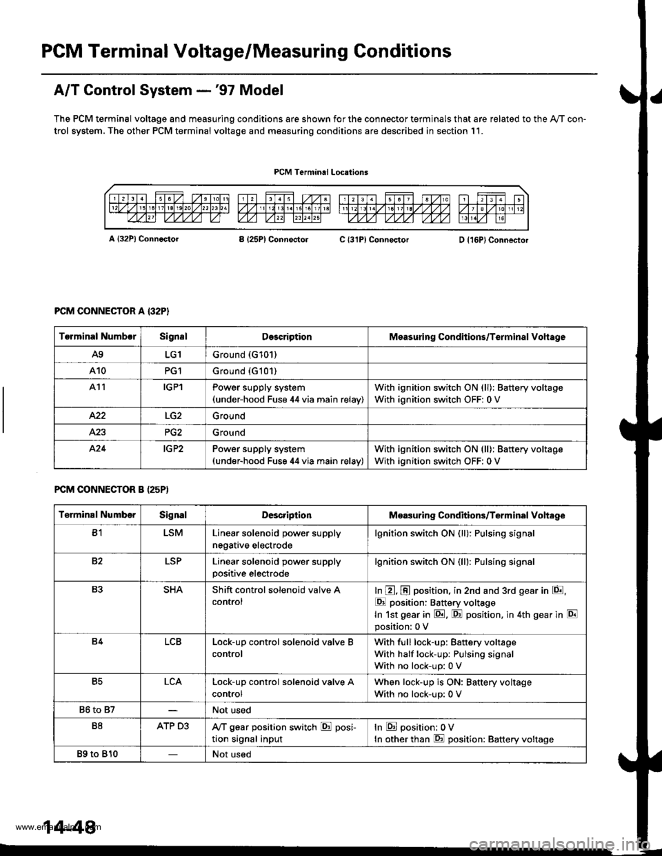
PGM Terminal Voltage/Measuring Conditions
A/T Control System -'97 Model
The PCM terminal voltage and measuring conditions are shown for the connector terminals that are related to the Ay'T con-
trol system. The other PCM terminal voltage and measuring conditions are described in section 11.
PCM Terminal Locations
A {32P} ConnectorB (25P1 ConnectolC {31PI ConnectorD {16P}Connector
PCM CONNECTOR A {32P}
FCM CONNECTOR B (25P)
Torminal NumbcrSignslDescriptionMeasuring Conditions/Terminal Vohage
A9LG1Ground (G101)
A10PG1Ground {G101)
At1IGPlPower supply system(under-hood Fuse 44 via main relav)
With ignition switch ON (ll): Battery voltage
With ignition switch OFF: 0 V
422Ground
Ground
424IG P2Power supply system(under-hood Fuse 44 via main relav)
With ignition switch ON (ll): Battery voltage
With ignition switch OFF: 0 V
Terminal NumberSignalDescriptionMeasuring Conditions/Terminal Vohage
B1LSMLinear solenoid power supply
negative electrode
lgnition switch ON (ll): Pulsing signa
82LSPLinear solenoid power supply
positive electrode
lgnition switch ON (lll: Pulsing signa
B3SHAShift control solenoid valve A
control
In @, @ position, in 2nd and 3rd gear in E,
E position: Battery voltage
In 1st gear in E. F! position, in 4th gear in E
position: 0 V
B4LCBLock-up control solenoid valve B
control
With full lock-up: Battery voltage
With half lock-up: Pulsing signal
With no lock-up: 0 V
B5LCALock-up control solenoid valve A
control
When lock-up is ON: Baftery voltage
With no lock-up: 0 V
86 to 87Not used
B8ATP D3,VT gear position switch E posi-
tion signal input
In E position: 0V
In other than E position: Battery voltage
89 to 810Not used
14-48
www.emanualpro.com
Page 565 of 1395

PCM CONNECTOR B (25P) lcont'd)
PCM CONNECTOR C {31PI
PCM CONNECTOR D II6PI
Terminal NumbelSignalDescriptionMeasuring Conditions/Terminal voltage
811SHBShift control solenoid valve B
control
In E, E position, in 1st and 2nd gear in -q,
Er position: Battery voltage
In B position, in 3rd gear in qd, q:l,in atn
gear in D. position: 0 V
812ILUlnterlock controlWhen ignition switch is ON (ll), brake pedal
deDressed and accelerator oedal released:0 V
B13D4 INDD4 Indicator light controlWhen ignition switch is first turned ON (ll): 6 V
or more for tlvo seconds
In lDll position: 6V or more
814NMSGMainshaft speed sensor ground
815NMMainshaft speed sensor signal
InpuI
Depending on engine speed: Pulsing signal
When engine is stopped: 0 V
816ATP RAy'T gear position switch Eposition signal input
In E position; OV
In other than E position: Battery voltage
817ATP 2Ay'T gear position switch E posi-
tion signal input
InEposition:0V
In other than E position: Battery voltage
B18ATP 1A/T gear position switch El posi-
tion signal input
InEposition:0V
In other than E position: Battery voltage
819 to 821Not used
B�22NCSGCountershaft speed sensor ground
NCCountershaft speed sensor signal
Inpur
Depending on vehicle speed: Pulsing signal
when vehicle is stooped: 0 V
824ATP D4A/T gear position switch iql posi-
tion signal input
In E position: 0V
In other than lgal position: Baftery voltage
825ATP NPAy'T gear position switch E and
N position signals input
In E and E positions: 0V
In otherthan @ and ffi positions:5 V
Terminal NumberSignalDescriptionMeasuring Conditions/Terminal Voltage
SCSService check signalWith ignition switch ON (ll) and service check
connector open: 5 V
With ignition switch ON (ll) and service check
connector connected with special tool: 0 V
c10VBUBack-up power system(under-hood Fuse 47)
Always battery voltage
Terminal NumberSignalDescriptionMeasuring Conditions/Terminal Voltage
STOP SWBrake switch signal inputBrake pedal pressedr Battery voltage
Brake pedal released: 0 V
14-49
www.emanualpro.com
Page 570 of 1395

PCM Terminal Voltage/Measuring Conditions
A/T Control System -'98 - 00 Models
The PCM terminal voltage and measuring conditions are shown for the connector terminals that are related to the A"/T con-
trol system. The other PCM terminal voltage and measuring conditions are described in section 11.
FCM Connector Terminal Localions
NOTE: 819 and C3 terminalsare applied to'99 - 00 models.
o (16Pt
T6rminal NumberSignalDescriptionMeasuring Conditions/Terminal Voltage
A5CRSDownshift signal input from
cruise control unit
When cruise control is used; Pulsing signal
A10scsTiming and adjustment service
check signal (5 V from PCM)
With ignition switch ON (ll) and service check
connector open:5 V
With ignition switch ON (ll) and service check
connector jumped with special tool: 0 V
A14('98 model)
D4 INDD4 indicator light control
{Voltage from PCM turns D4 light
oN)
When ignition switch is first turned ON (ll):
Battery voltage for two seconds
In E position: Battery voltage
A14
('99 - 00 models)
D INDD indicator light control(Voltage from PCM turns D light
oN)
When ignition switch is first turned ON (ll):
Baftery voltage for two seconds
ln E position: Battery voltage
428ILUInterlock control(Voltage from PCM)
When ignition switch ON {ll), brake pedal
depressed, and accelerator pedal released:
Battery voltage
A.32STOP SWBrake switch signal inputBrake pedal pressed; Battery voltage
Brake pedal released: 0 V
FCM CONNECTOR B I25P}
Terminal NumberSignalDescriptionMeasuring Conditions/Terminal Voltage
B1IGPlPower supply circuit from main
relay via under-hood Fuse 44
With ignition switch ON {ll): Battery voltage
With ignition switch OFF: 0 V
82PG1Ground (G101)
B8LSMLinear solenoid power supply
negative electrode
IG P2Power supply circuit from main
relay
With ignition switch ON (ll): Baftery voltage
With ignition switch OFF: 0 V
810PG2Ground (G101)
B17Linear solenoid power supply
positive electrode
With ignition switch ON (ll): Pulsing signal
819
('99 - 00 models)
O/D INDOver-Drive (O/D) OFF indicator
light control
When ignition switch is first turned ON (ll):
0 V for two seconds
O/D OFF indicator light ON:0 V
O/D OFF indicator light OFF: Battery voltage
s20Ground (G101)
B�21VBUBack-up power supply(under-hood Fuse 47)
Always battery voltage
B�22LG2Ground (G101)
14-54
www.emanualpro.com