23 page HONDA CR-V 1997 RD1-RD3 / 1.G Workshop Manual
[x] Cancel search | Manufacturer: HONDA, Model Year: 1997, Model line: CR-V, Model: HONDA CR-V 1997 RD1-RD3 / 1.GPages: 1395, PDF Size: 35.62 MB
Page 309 of 1395
![HONDA CR-V 1997 RD1-RD3 / 1.G Workshop Manual
The scan tool indicates Diagnostic Trouble Code (DTC) P0123: A high voltage problem in the Throttle Position
(TP) sensor circuit.
TP SENSOR 3P @]{NECTOR IC13O}
sG2(GnN/Br.XlvocrtYEt /8LU)
{GBIT/BLKI
HONDA CR-V 1997 RD1-RD3 / 1.G Workshop Manual
The scan tool indicates Diagnostic Trouble Code (DTC) P0123: A high voltage problem in the Throttle Position
(TP) sensor circuit.
TP SENSOR 3P @]{NECTOR IC13O}
sG2(GnN/Br.XlvocrtYEt /8LU)
{GBIT/BLKI](/img/13/5778/w960_5778-308.png)
The scan tool indicates Diagnostic Trouble Code (DTC) P0123: A high voltage problem in the Throttle Position
(TP) sensor circuit.
TP SENSOR 3P @]{NECTOR IC13O}
sG2(GnN/Br.XlvocrtYEt /8LU)
{GBIT/BLKI
(cont'd)
11-107
Wiro side of fom.le terminals
PCM CON'{ECTOF D I16PI
Wire side ot female terhinals
The MIL hlr br€n r.9ort.d on.DTC P0123 ir stored.
Pioblom vorificltion:1. Start the ongin6. Hold th€ongine at 3,000 rpm with noload {in Park or neutral) untilth6 radiator fan comes on.then turn the ignition switchOFF,2. Turn the ignition switch ON (ll).
3. Check the throttle position
with the scan tool.
Intarmittant tailuro, ryrtern b OKat this timo. Chock lor poor con-nections or loo3o wir€3 at C130
ITP 3orcorl .nd at tho ECM/FCM.
ls there spprox. 1oyo when thothrottle is Iully closed andapprox.90% when the throttleis tully open€d?
Choct toJ an opcn in th6 TP s6n-3t']:1. Turn the ignition switch OFF.2. Disconnect the TP sensor 3Pconnectol,3. Turn the ignition switch ON (ll).
4. At the wir6 harnoss side, mea-suro voltage betweon thg TPsensor 3P connector t€rminalsNo. 1 and No.3.
ls there approx.5 V?
Chack for an oDan in tha wira(SG2 linel:M6asu16 voltage b6tween PCMconn€ctor terminals Dl0 and D'! 1.
R.pai. opcn in tha wira botwcontho PcM {o111 rnd the TP 3en-3('t,
ls there approx. 5 V?
('97 model)
(To page 11-108)
www.emanualpro.com
Page 310 of 1395
PGM-FI System
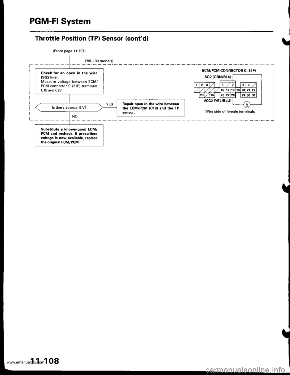
(From page 11-107)
Check lor an open in the wirc(SG2line):
Measure voltage between ECM/PCM connector C (31P) terminalsC18 and C28.
Ropair open in th€ wire betweonrhe ECM/PCM (Cl81 .nd the TP56nSOl,
ls there approx. 5 V?
Substitute a known-good ECM/PCM and rocheck. lf pre3cribedvoltago is now avaibble, replacetho origin.l ECM/PCM,
Throttle Position (TP) Sensor (cont'dl
ECM/PCM CONNECTOR C {31PI
Wire side of temale terminals
1 1-108
www.emanualpro.com
Page 312 of 1395
PGM-FI System
Primary Heated Oxygen Sensor (Primary HO2S) (Sensor 1)
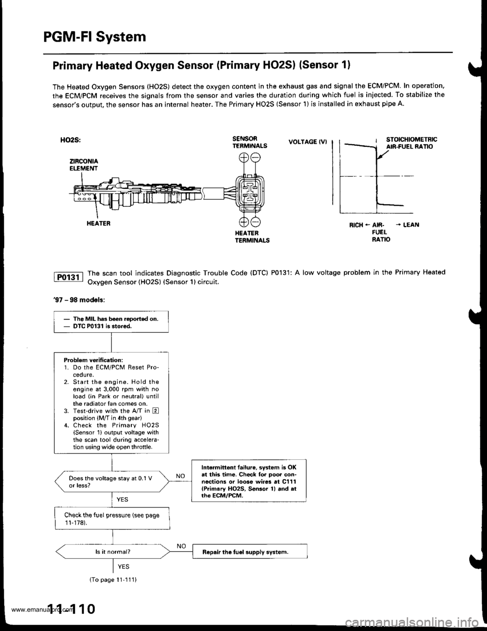
The Heated Oxygen Sensors (HO2S) detect the oxygen content in the exhaust gas and signal the ECM/PCM. In operation,
the ECM/PCM receives the signals from the sensor and varies the duration during which fuel is iniected. To stabilize the
sensor's output, the sensor has an internal heater. The Primary HO2S (Sensor 1) is installed in exhaust pipe A.
HO2S:
ztRcoNtAEI.IMENT
s€NsoRTERMINALSVOLTAGE IVI
HEATEBTERMINALS
The scan tool indicates Diagnostic Trouble Code (DTC) P0131: A low voltage
Oxygen Sensor (HO2S) {Sensor 1} circuit,
RICH - AIR. . LEANFUELNATO
problem in the Primary Heated
37 - 98 models:
HEATER
The MIL has been reoorted on.DTC P0131 is stoied.
Problem verification:1. Do the ECM/PCM Reset Pro-ceoure.Start the engine. Hold theengine at 3,000 rpm with noload (in Park or neutral) untilthe radiator fan comes on.Test-drive with the A/T in Eposition (M/T in 4th gear)Check the Primary HO2S{Sensor 1} output voltage withthe scan tool during accelera-tion using wide open throttle.
Intermittent f.ilure, system is OKat this time. Check fo. poor con-nections or loose wirer at C111(Primary HO2S, SeGor 1) and atrh€ ECM/FCM.
Check the fuel pressure (see page
11-178).
Repair the fuel supply system.
{To page 11'111}
1 1-1 10
www.emanualpro.com
Page 313 of 1395
{From page 11-110}
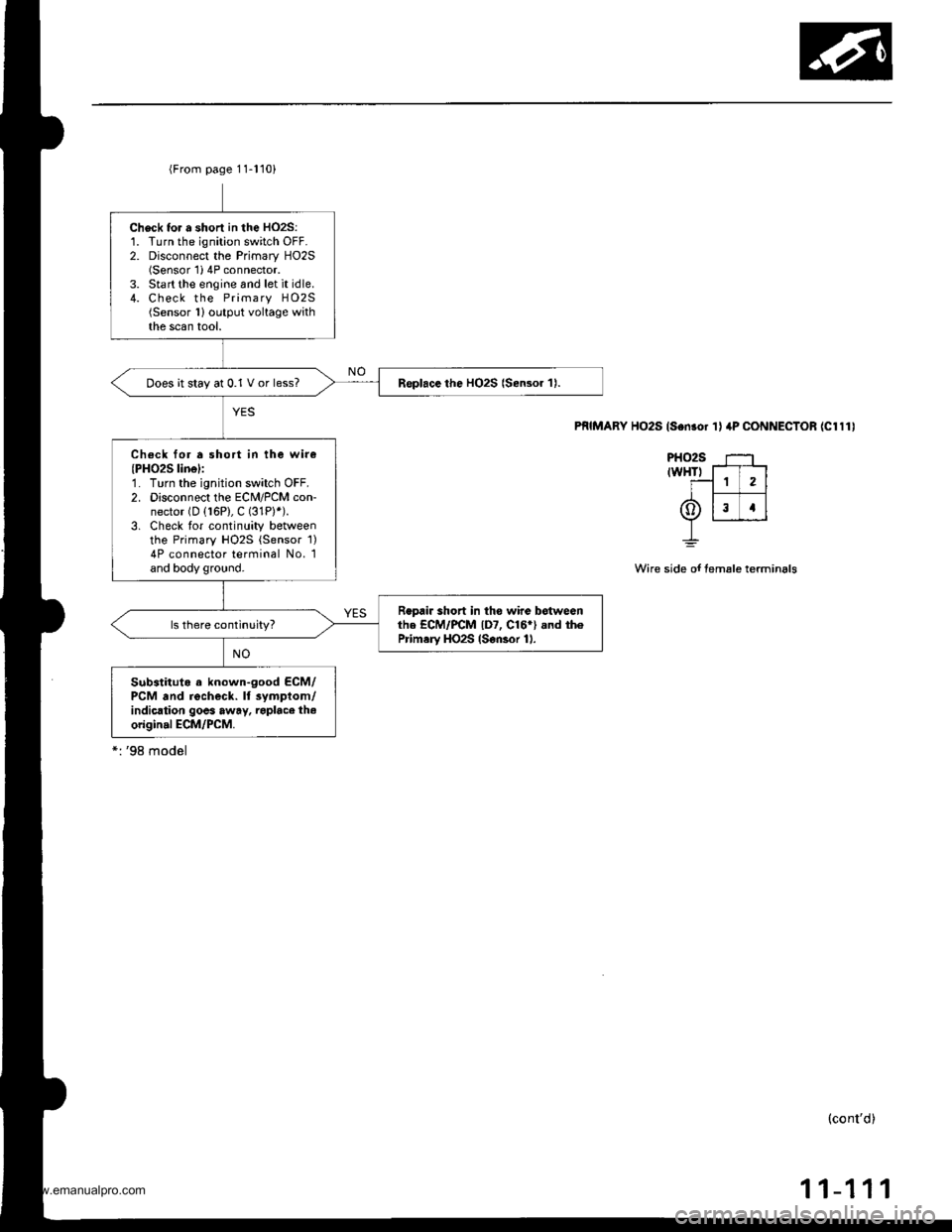
Check tor a shorl in the HO2S:1. Turn the ignition switch OFF.2. Disconnect the Primary HO2S(Sensor'1i 4P connector.3. Start the engine and let it idle.4. Check the Primary HO2S(Sensor 1)output voltage withthe scan tool.
Replace the HO2S {Sensor 1).Does it stay at 0.1 V or less?
Check for a short in the wir€(PH02S linel:1. Turn the ignition switch OFF.2. Disconnect the ECM/PCM con-nector (D (16P), C (31P)*).
3. Check tor continuity betweenthe Primary HO2S {Sensor 1)4P connector terminal No. 1and body ground.
Repair short in tho wire botwesnthe ECM/PCM lD7, C16*) .nd th6Prim.ry HO2S (S€nsor 11.
Substituto a known-good ECM/PCM and recheck. ll 3ympiom/indication goes away. raplace th.origin.l ECM/PCM.
PRIMARY HO2S ls.n.or 'l I 4P CONNECTOR (Cl111
PHO2S ---'trwHTr T-T-l
T-1 1 2l
6tlr rlY r___J_J
L
Wire side of temale terminals
(cont'd)
11-111
www.emanualpro.com
Page 315 of 1395
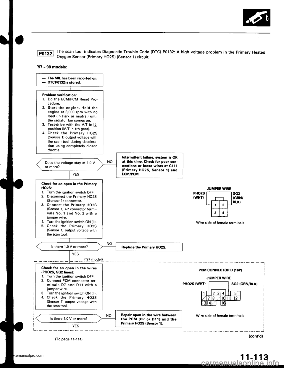
The scan tool indicates Diagnostic Trouble Code (DTC) P0132: A high voltage problem in the Primary HeatedOxygen Sensor {Primary HO2S) (Sensor 1) circuit.
'97 - 98 models:
PHO2S
IWHTIsG2IGRN/BLK}
Wire side ot female terminals
PCM CONNECTOR D {16PI
JUMPER WIRE
PHO2S IWHTISG2 IGRN/BLK}
Wire side of temale terminals
I
(cont'dl
11-113
Problem verification:1. Do the ECM/PCM Resot Pro,ceoute,2. Start the engine. Hold theengine at 3,000 rpm with noload (in Park or neutral) untilthe radiator fan comes on.3. Test-drive with the Ay'T in Eposition (M/T in 4th gear).4. Check the Primary H02S{Sensor 1}output voltage withthe scan tool during decelera-tion using completely closedthrottle.
Intormittent l.ilure, 3ystem ia OKat thb timo. Chcck fo. poor con-nections 01 looso wi.es at C111{Prim!ry HO2S, Sensor 1} andECM/PCM.
Does the voltage stay at 1.0 V
Check for an open in th6 PrimaryH()2S:1. Turn the ignition switch OFF.2. Disconnect the Primary HO2S(Sensor 1) connector-3. Connect the Primary HO25lSensor 1) 4P connector termi-nals No. 1 and No. 2 with ajumper wire.4. Turn the ignition switch ON (ll).5. Check the Primary HO2S(Sensor 1) output voltage withthe scan tool,
ls there 1.0 V or more?
Ch€ck for an opon in the wires(PHO2S, SG2linesl:1. Turn the ignition switch OFF.2. Connect PCM connector ter-minals D7 and Dl1 with a
3. Turn the ignition switch ON (ll).4. Check the Primary HO2S{Sensor 1) output voltage withthe scan tool.
Roprir opon in the wire betweontho PCM {D7 01 D11l and thePrimsry HO2S {S6nsor 1).
ls there 1.0 V or more?
{'97 model}
{To page 11-114)
www.emanualpro.com
Page 316 of 1395
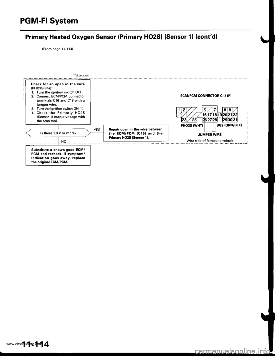
PGM-FI System
Primary Heated Oxygen Sensor lPrimary HO2S) {Sensor 1} {cont'dl
(From page'11-l13)
ECM/PCM CONNECTOR C {31PI
11-114
Ch.ck for an open in the wire(PHO2S linel:1. Turn the ignition switch OFF.2. Connect ECM/PCM connectorterminals C16 and C18 with a
3. Turn the ignition switch ON {ll).4. Check the Primarly H02S(Sensor 1) output voltage withthe scan tool.
R€p.ir open in the wire bqtw€enthe ECM/PCM (C161 and th€Primary HO2S (Sen.or'l).ls there 1,0 V or more?
Substitute a known-good ECM/PCM and rach€ck. lt 3ymptom/indication goos away, replacethe origin.l ECM/PCM.
www.emanualpro.com
Page 320 of 1395
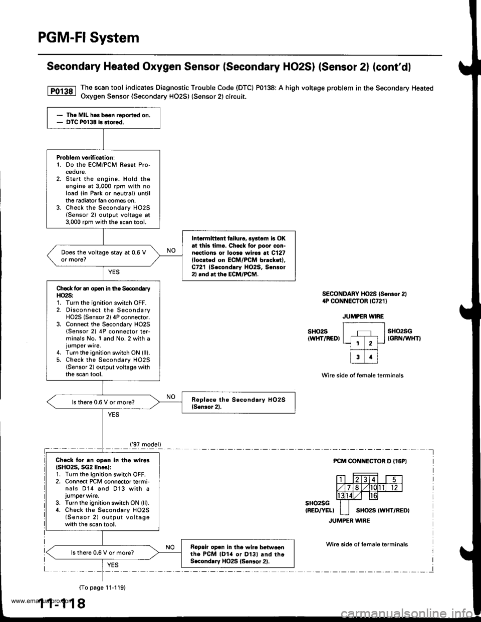
PGM-FI System
Secondary Heated Oxygen Sensor (Secondary HO2SI (Sensor 2l (cont'dl
The scan tool indicates Diagnostic Trouble Code (DTC) P0138: A high voltage problem in the Secondary Heated
Oxygen Sensor (Secondary HO2S) (Sensor 2) circuit.
SECONDABY HO2S (Sonror 2)1P CONNECTOR rC721 l
sHo2s{WHT/REDI
sH()2sGIGFN/WHTI
Wire side of female terminals
PCM COI{NECTOR D {16PI
sHo2sG(RED/YELI
JUMPER WIRE
Wirc side ol lemale terminals
{To page 11-119)
1 1-1 18
The MIL hra b€on Eported on,OTC m138 b stor.d.
PJoblcm v6dtic.tion:1. Do the ECM/PCM Resot Pro-cedure,Start the engine. Hold theengine at 3,000 rpm with noload (in Park or neutral) trntilthe radiator lan comes on.Check the Secondary HO2S(Sensor 2) outpl.rt voltage at3,000 rpm with the scan tool.
Int.rmitto tailurc, syst.m b OKrt ihi! timo. Chack fo. poo. oon-noctioni or looaa wiiaa at C127lloc.ted on EcM/PcM br.cket),C721 (Second!ry llO2S, Sonlol2).nd at th. ECM/PCM.
Does the voltage stay at 0.6 Vor more?
Chock for an opon in the SocondaryHO2S:1. Turn the ignition switch OFF.2. Disconnect the SecondaryHO2S (Sensor 2) 4P connector.3. Connect the Socondary HO2S(Sensor 2) 4P connector ter-minals No. 1 and No. 2 with a
4. Turn the ignition switch ON {ll}.5. Check the Secondary HO2S{Sensor 2) output voltage withthe scan tool.
ls there 0.6 V or more?
Ch6ck for an open in thg wiro3(SH()2S, SG2 line3l:1. Turn the ignition switch OFF.2. Connect rcM connector termi-nals 014 and D13 with a
J!mper wite.3. Turn the ignition switch ON (ll).
4. Check the S€condary HO2S(S€nsor 2) output voltagewith the scan tool.
Rapair op6n in tho wir. b€{woantho PcM lDla or Dl3l .nd thoS.condlry HO2S {Senlor 21.
lsthere 0.6 V or more?
('97 model)
www.emanualpro.com
Page 321 of 1395
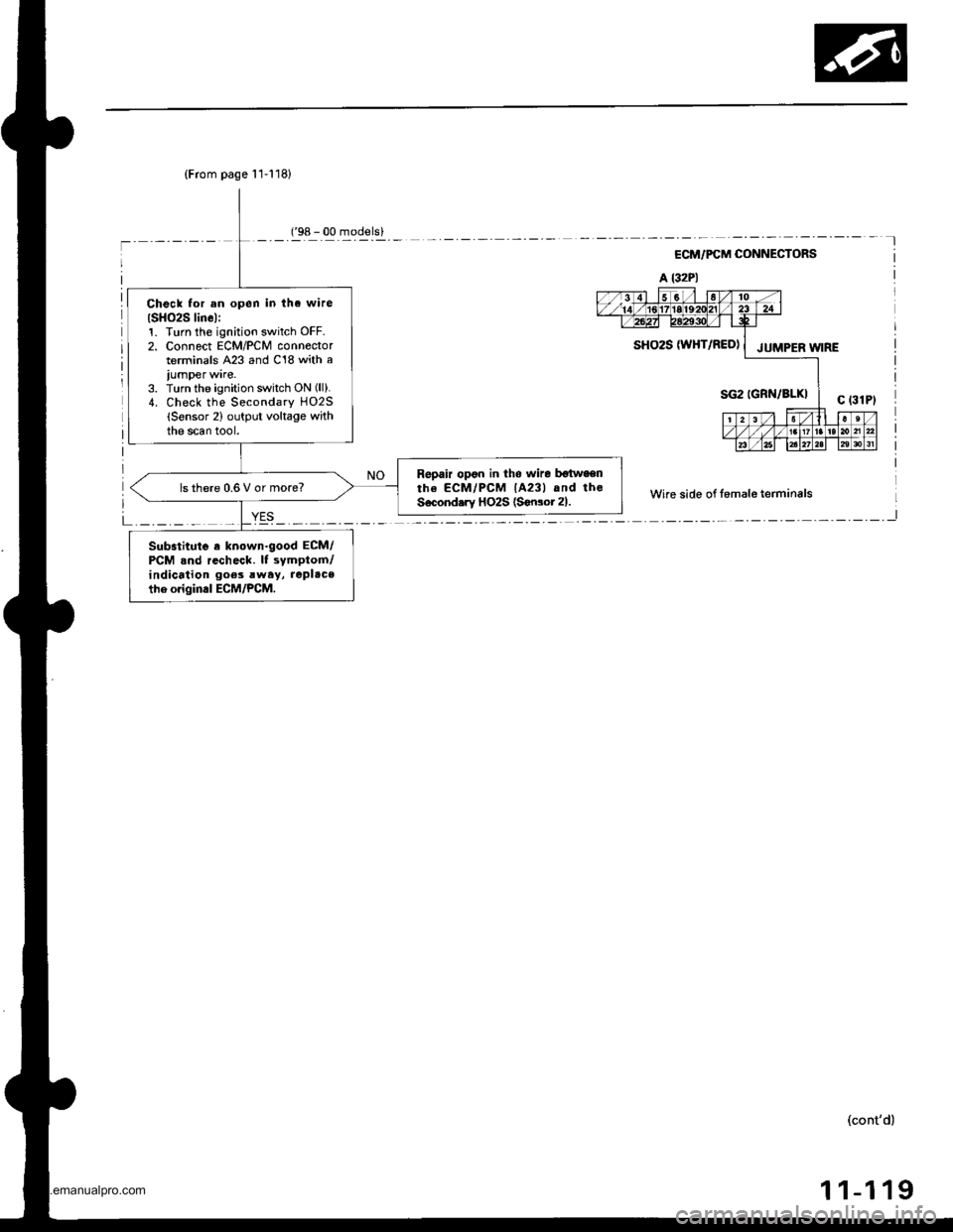
(From page 11-118)
Check for an open in tha wire
ISH()2S linel:1. Turn th€ ignition switch OFF.2. Connect ECM/PCM connectorterminals A23 and C18 with a
iumper ware.3. Turn the ignition switch ON (ll).
4. Check the Secondary HO2S(Sensor 2) output voltage withthe scan tool.
Repair opon in tho wire botwaenthe ECM/PCM lA23l and theSecond.ry HO2S (Sonsot 21.ls there 0.6 V or more?
Substitute a known.good ECM/PCM .nd recheck. It symptom/indication goes rway, replace
the origin.l ECM/PCM.
('98 - 00 models)
ECM/PCM CONNECTORS
A l32Pl
Wire side of fomale terminals
L _._._ _ _I
SHO2S W}iT/RED) | JUMpER W;RE
(cont'd)
1 1-1 19
www.emanualpro.com
Page 323 of 1395
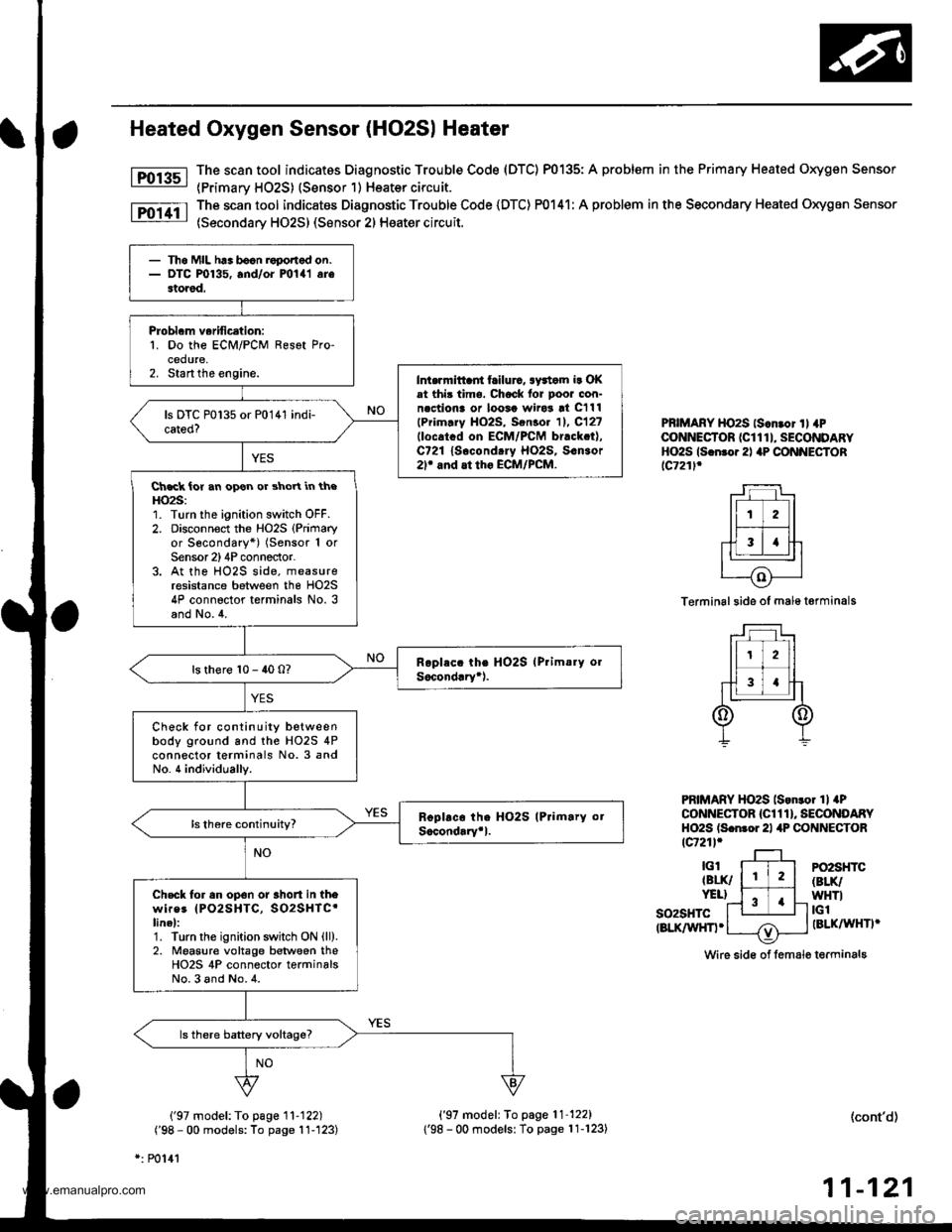
Heated Oxygen Sensor (HO2S| Heater
The scan tool indicatos Diagnostic Trouble Code (DTC) P0135: A problem in the Primary Heated Oxygen Sensor
{Primarv HO2S) (Sensor 1) Heater circuit.
The scan tool indicates Diagnostic Trouble Code (DTC) P0141: A problem in the Secondary Heated Oxygen Sensor
(Secondary HO2S) (Sensor 2) Heater circuit.
Fol3sl
Fo11tl
PBIMARY HO2S ls.n.or ll 4PCONNECTOR (CI 1 1 I, SECONDARYHO2S ls.n.o.2l aP CONNECTORlc721l.
Terminal side of male t€rminals
PRIMARY HO2S lson.o. 1l aPCONNECTOR {Cl 1 1 }, SECONDARYHO2S ls.nror 21 4P CONNECTORtcr21l.
so2sHTctBLK/WHn.
PO2SHTC(BLK/
WHTItGlIBLKAAIHTI'
Wire sid€ of lemale terminals
('97 model: To page '11-122)
('98 - 00 models: To page 11-'123)
*: P0141
('97 model: To page'11-122)
1'98 - 00 modelsl To page 11-123)(cont'd)
11-121
- Th6 MIL h.. bocn roponod on.- DTC P0135, and/oi mlal arestored.
Probl.m verification:1. Do the ECM/PCM Resot Pro-cedure,2. Start the engine.Int.rrnittaii frilurc, awtom ir OKat thi3 time. Chock lor poor con-n.ctiona or loosa wiro3 !t C111
lPrim.ry HO2S, Sen3o. 11. C12?llocatcd on ECM/PCM br.ck.t),C721 lsocond.ry Ho2s, s.n3or2r and at tho ECM/PCM.
Ch.ck ior an opon or shoYt in theHO2S:1. Turn the ignition switch OFF.2. Disconnoct the Ho2s (Primary
or Secondary*) (Sensor 1 orSensor 2)4P conneclor.3. At the HO2S side, measureresistance between the HO2S4P connector terminals No. 3and No.4.
ls there 10 - 40 0?
Check for continuity betweenbody ground and the HO2S 4Pconnector terminals No. 3 andNo. 4 individually.
Check tor an op6n or 3hort in thewires IPO2SHTC, SO2SHTC'linel:1. Turn the ignition swhch ON {ll).2. Moasure voltage between theHO2S 4P connector terminalsNo.3 and No.4.
www.emanualpro.com
Page 324 of 1395
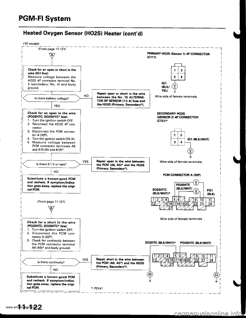
PGM-FI System
Heated Oxygen Sensor IHO2S) Heater (cont'd)
{'97 model)
(From page l1-121)
PRIMARY HO2S (S.nsor 1) ap CONNECTOR{cl111
| 112 ||.�i-l
13 .l
'ot X-tErK/ (9YELI -L
Wire side of female terminals
SECONDARY HO2SISENSOR 21 4P CONNECTORlcr21l,
IGl IBLK/WHTI
Wire side ol female terminals
Wire side of female terminals
So2HTCIALK/WHTI* PO2SHTCIBLK/WHTI
Chock for en open or lhort in thewire (lG1 line):Measure voltage between theHO2S 4P connector terminal No.3 (secondary: No. 4) and bodyground,
Reprir op6n or 3hort in thc wircbetwo.n th€ No. 15 ALTERNA-TOR SP SENSOR (7.5 Al fu!. rndtho HO2S (Primary. Socond.ry*).
Ch€ck for an open in the wire(PO2SHTC, SO2SHTC. lin€):1. Turn the ignition switch OFF.2. Reconnect the HO2S 4P con-
3. Disconnect the PCM connec-tor A (32P).4. Turn the ignition switch ON (ll).5. Measure voltage betweenPCM connector t€rminals 46and A10 (A5 and A10)*.
Bepair opon in the wiro botwoonthe PcM (A6. A5lr and tho Ho2s{Prim.ry, Socond!ryr}.
ls thero 0.1 V or less?
Substitute a lnown-good PCMand recheck. lt 3ymptom/indica-tion goes away, .oplaco the origi-nal PCM.
Check fo. a ahort in the wireIPO2SHTC, SO2SHTC. lins):1. Turn the ignirion switch OFF.2. Disconnect the PCM con-nector A {32P).3. Check lor continuily betweenthe PCM connector terminal46 (A5)* and body ground.
Bopair short in the wire lrotwsentho PC{r4 {A6, A5rl and the HO2SlPiimary, S€condary.l.
Substitute a known-good PCMand .echgck. lf 3ymptom/indica-tion go€s awry. repl.cethe origi-nal PCM.
11-122
www.emanualpro.com