air con HONDA CR-V 1997 RD1-RD3 / 1.G Workshop Manual
[x] Cancel search | Manufacturer: HONDA, Model Year: 1997, Model line: CR-V, Model: HONDA CR-V 1997 RD1-RD3 / 1.GPages: 1395, PDF Size: 35.62 MB
Page 416 of 1395
Emission Control System
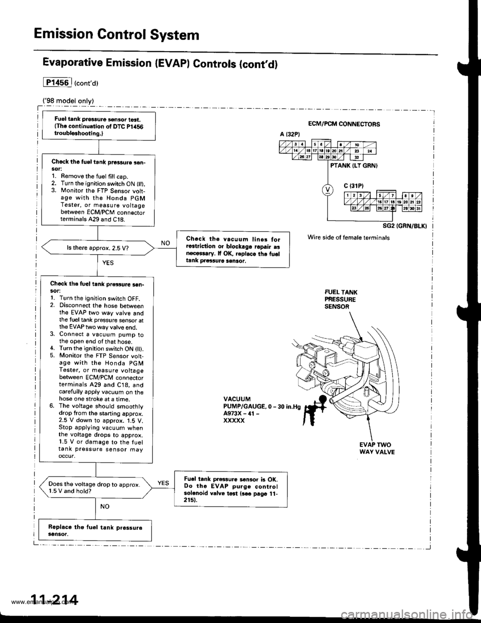
Fuel tank pros3ure sensor tost.(The continuetion of DTC Pl456t.oubls3hooting.,
Chock the tusl trnk pr€3sure sen-sor:1. Remove the fuel fill csp.2. Turn the ignition switch ON fll).3. Monitor the FTP Sensor voh-age with th€ Honda PGMTester, or measure voltagebetween ECM/PCM conn€ctorterminals A29 and C18.
Choct ths vacuum linsr forra3triction o. blockago ropair a!nect*rary. It OK, replaca the fu6ltank praituJc sentot.
ls there approx. 2.5 V?
Check the fuel t nk pressuae 3en-sor:1. Turn the ignition switch OFF.2. Disconnect the hose betweenthe EVAP two way valve andthe tueltank pressure sensor atthe EVAP two way valve end.3. Connect a vacuum pump tothe open end ofthat hose.4. Turn the ignition switch ON 0l).5. Monitor the FTP Sensor volt-age with the Honda PGMTestet, or measure voltagebetween ECM/PCM connectorterminals 429 and C18, andcarefully apply vacuum on thehose one stroke at a lime.6. The voltage should smoothtydrop from the staning approx.2.5 V down to approx. 1.5 V.Stop applying vacuum whenthe voltage drops to approx.1.5 V or damage to the fueltank pressure sensor fiayoccur,
Fu.l tank pressu.c a€nlor b OK.Oo thc EVAP pulge controlsolenoid valve toat (3€€ prgo 11-2151.
Does the voltage drop to approx.1.5 V and hold?
Evaporative Emission (EVAPI Controls (contd)
lP14s6l("ont,a)
ECM/PCM CONNECTORS
SG2 IGRN/BLKI
Wire side oI female terminals
FUEI- TANKPRESSURESENSOR
VACUUMPUMP/GAUGE,0 - 30 in.HgA973X - ill -
xxxxx
EVAP TWOWAY VALVE
11-214
www.emanualpro.com
Page 418 of 1395
Emission Control System
Evaporative Emission (EVAPI Controls (cont,dl
1T1456I (conro)
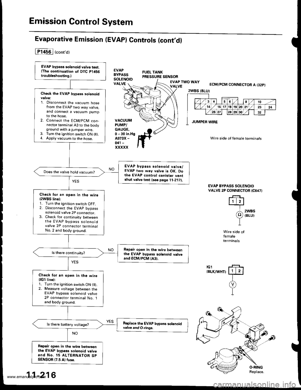
€VAPBYPASSSoLENOtOVALVEECM/PCM CONNECTOR A I32P)
Wire side of female terminals
VACUUMPUMP/GAUGE.0 -30 in.HgA373X -
041 -
xxxxx
EVAP BYPASS SOLENOIDVALVE 2P CONNECTOR lcorlTl
2WBS(BLU}
II
Wire side offemaletermrnats
tGlIBLK/WHT}
EVAP bypa3s solenoid valve test.(The continuation ot DTC P1456troubleshooting.l
Check the EVAP bypass sotenoid
1. Disconnect the vacuum hosefrom the EVAP two way valve,and connect a vscuum pumpto the hose,2. Connect the ECM/PCM con-nector terminal 43 to the bodyground with a jurnper wire.3. Turn the ignition switch ON 0t).4. Apply vacuum to the hose.
EVAP bypass solenoid valve/EVAP two way valve is OK. Doth6 EVAP control crnister ventshut vafve le3t lso€ page 11-2'111.
Does the valve hold vacuurn?
Check for an op€n in the wir€(2WBS line):1. Turn the ignition switch OFF.2. Disconnect the EVAP bypasssolenoid valve 2P connector.3. Check for continuity betweenthe EVAP bypass so teno idvalve 2P connector terminalNo. 2 and body ground.
Repair open in the wire betweenthe EVAP bypass solenoid valv.and ECM/PCM lA3).
Chack tor an op6n in the wirellcl line):1. Turn the ignition switch ON l).2. Measure voltage between theEVAP bypass solenoid valve2P connector terminal No. land body ground.
Replace the EVAP byps.,s solonoidvatus and O-ring3.
Ropair o,pen in the wire botwoenth6 EVAP bypa$ sotenoid vatvoand No. 15 ALTERNATOR SpSENSOR (7.5 Altuso.
2WBS (BLU}
/3
7,x
4l6o/to -/
,/ 16 1718't920 211/z3
26 272A29solT32
JUMPER WIRE
11-216
www.emanualpro.com
Page 420 of 1395
Emission Control System
Evaporative Emission IEVAPI Controls (cont'd)
lTi,t56l ("onto)
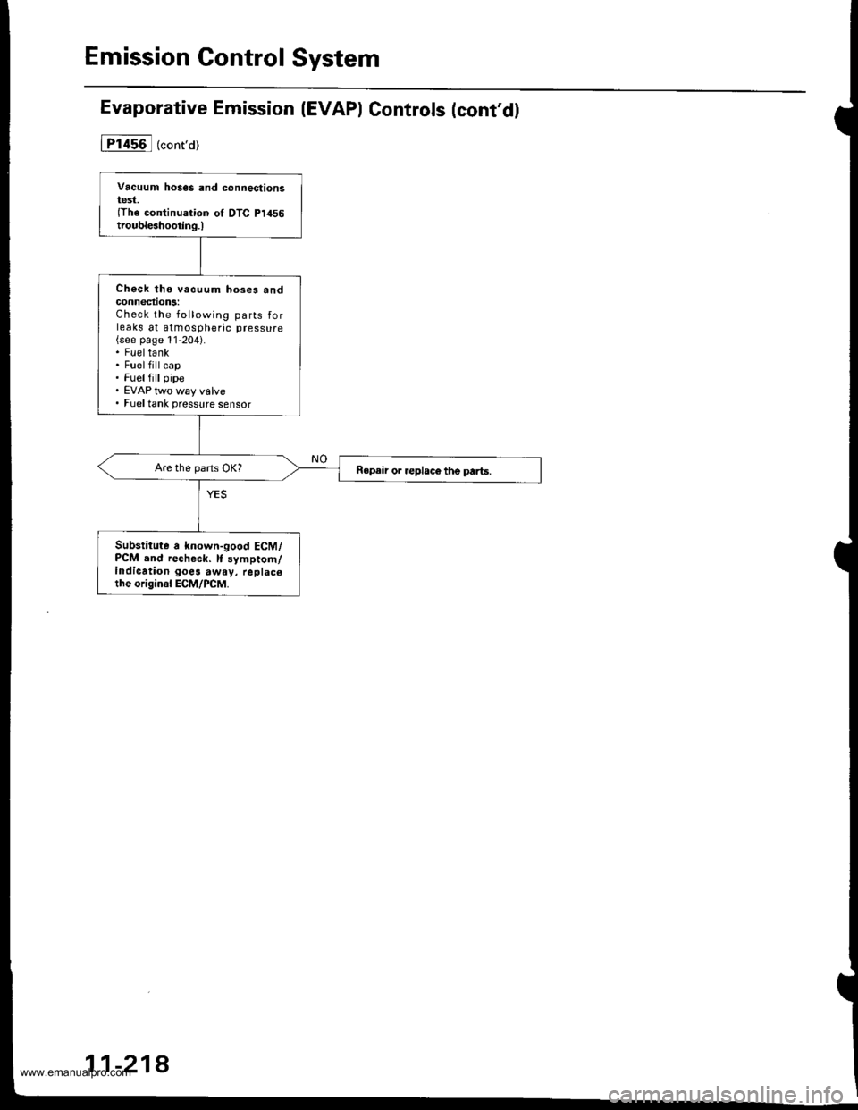
Vacuum hoses and connectionstelit.(The continuarion of DTC P1456troubleshooiing.l
Check the vacuum ho3es andconnect|ons:Check the following parts forleaks at atmospheric p ressu re{see page 11-204).. Fueltank. Fuel fill cap. Fuelfill pipe. EVAP two way valve. Fueltank pressure sensor
Repair or replaco the parts.
Substitute a known-good ECM/PCM and recheck. lf symptom/indication goes away, replac€the original ECM/PCM.
11-218
www.emanualpro.com
Page 422 of 1395
Emission Control System
Evaporative Emission (EVAP) Controls (cont,dl
iTl457l ("ont'or
APCONTROLCANISTER
Ropair op€n in th6 wire betweenthe EVAP purge control 3olenoidvelve and ths ECM/PCM (A61.
VACUUMPUMP/GAUGE, O-30 iN.HgA973X - 0rl -
xxxxx
'\)
Wire side of lemale terminals
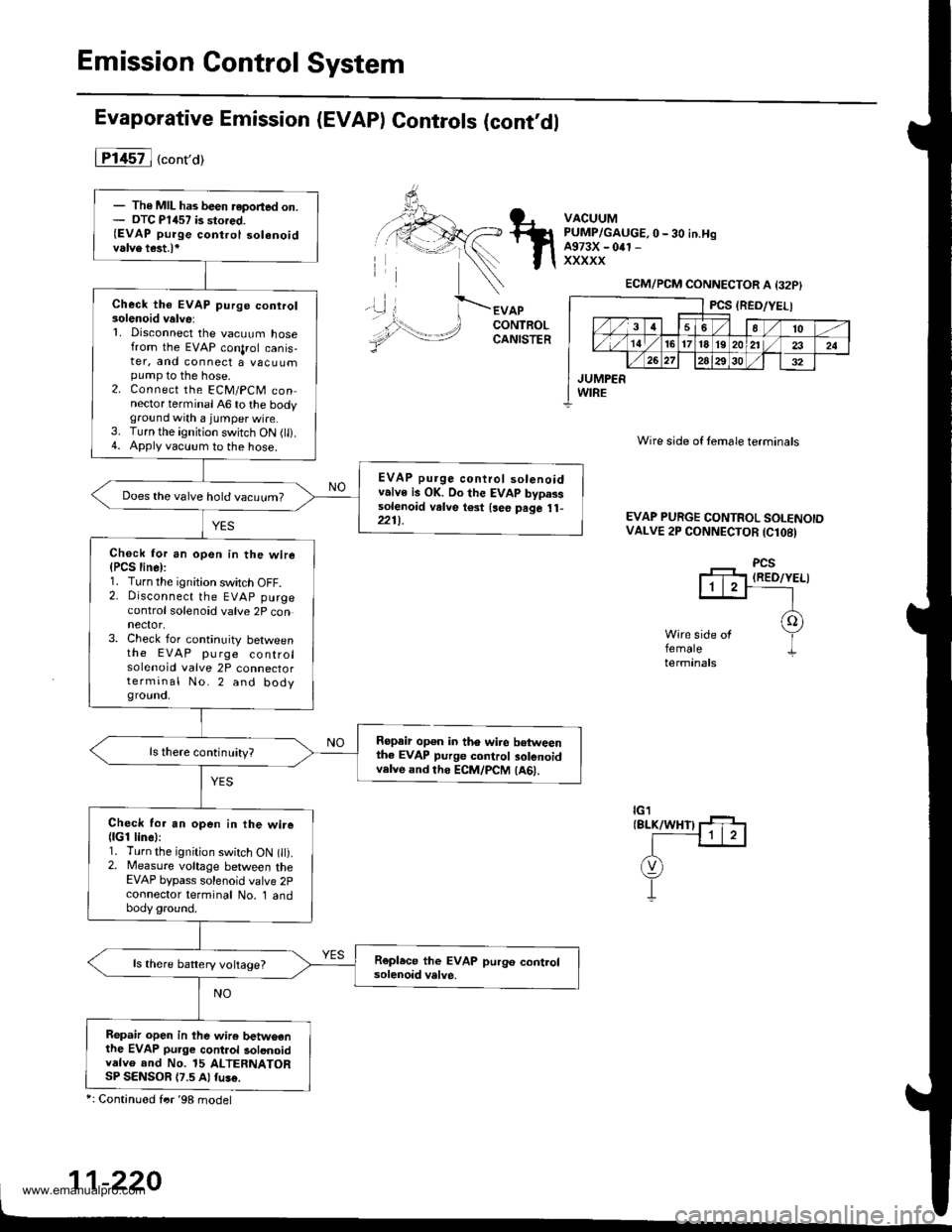
EVAP PURGE CONTROL SOI.ENOIDVALVE 2P CONNECTOR (Cl08)
PCSIRED/YELI
femaletermanals
ECM/PCM CONNECTOR A {32P}
PCS (RED/YELI
,/3 458/'t0
,,/ 14 ,/'t61718l92024
,/ 262930
JUMPERWIRE
- The MIL has been reported on.- DTC P1457 is stored.{EVAP purge control solenoidvalve test.l*
Check the EVAP purge conrrol30lenoid velve:L Disconnect the vacuum hosefrom the EVAP conlrol canis,ter, and connect a vacuumpump to the hose.2. Connect the ECM/PCM connector terminal A6 to the bodyground with a jumper wire.3. Turn the ignition switch ON (tl).4. Apply vacuum to the hose.
EVAP purge control solenoidvalve is OK. Oo the EVAP bypasssolenoid valve t€3t {see psge 1l-221t.
Does the valve hold vacuum?
Check for an open in the wire(PCS line):1. Turn the ignition switch OFF.2. Disconnect the EVAP purgecontrol solenoid valve 2P connector,3. Check for continuity betweenthe EVAP pu rge controlsolenoid valve 2P connectorterminal No.2 and bodygrouno,
ls there continuity?
Check for an open in the wire(lGl line):1. Turn the ignition switch ON t).2. Measure voltage between theEVAP bypass solenoid valve 2pcoonector terminal No. 1 andbody ground.
ls there battery voltage?
Repah open in lhe wir6 betwoenthe EVAP pu.ge cont.ol solonoidvdlvo and No. 15 ALTERNATORSP SENSOR {7.5 Al fu!€.
*: Continued frr '98 model
1-220
www.emanualpro.com
Page 425 of 1395
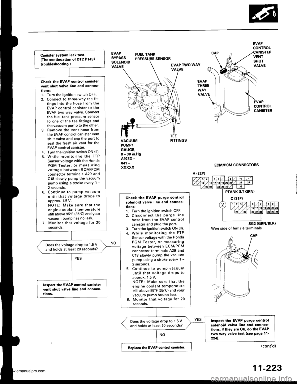
Canbter system leak test
{The continuation of DTC P1457
trouble3hootin9.)
Chock the EVAP control canistervent shut valve line and connoc'
tonS:1. Turn the ignition switch OFF
2. Connect to three'way tee fit_
tings into the hose from the
EVAP control canister to the
EVAP two way valve. Connect
the fuel tank pressure sensor
to one of the tee fittings and
the vacuum PumP to the other'
3. Remove the vent hose from
the EVAP control canister vent
shut valve and cap the Pon to
seal the fresh air vent Ior the
EVAP control canister.4. Turn the ignition switch ON (ll).
5. While monitoring the FTP
Sensor voltage with the Honda
PGM Tester, or measurangvoltage between ECM/PCM
connector terminals A29 and
C18 slowly PumP the vacuumpump using a stroke every 1 -
2 seconds.6. Continue to PumP vacuum
until that voltage droPs to
approx. 1.5 V.NOTE: Make sure that the
engine coolant temPeraturestillabove 95'F (35'Cland Yourvacuum PumP has no leak
7. Monitor that voltage for 20
seconds.
Check the EVAP Pu.ge control
solenoid valve line and connec-
tions:1. Turn the ignition switch OFF.
2. Disconnect the Purge lane
hose from the EVAP control
canister and Plug the Port3. Turn the ignition switch ON (lli.
4. While monitoring the FTP
Sensor voltage with the Honda
PGM Tester, or measuringvoltage between ECM/PCM
connector terminals A29 and
Cl8 slowly PumP the vacuumpump using a stroke every 1 -
2 seconds.5. Continue to pump vacuum
until that voltage droPs to
approx. 1-5 V.NOTE: Make sure that the
engine coolant temPeraturestill above 95'F (35"C) and Yourvacuum pump has no leak-
6. Monitor that voltage tor 20
seconds.
Doesthe voltage drop to 1.5 V
and holds at least 20 seconds?
lGp€ct the EVAP control cani3tel
vent 3hut valvo line and connec_
tion5.
Inlpect tho EVAP Putge control
solenoid valvo line and connec'
tion3. It th6y lro OK, do the EVAP
two way valve te3t (seo page 11-
2211.
Does the voltage drop to 1.5 V
and holds at least 20 seconds?
Reolace the EVAP conirol canister.
EVAPBYPASSSOLENOIDVALVE
FUEL TANK
EVAPCONTROL
VENTSHUTVALVE
EVAPCONTROLCANISTER
SENSOR
EVAP TWO WAYVALVE
EVAPTHREE
VALVE
ttrrL
ta
VACUUMPUMP/GAUGE,0 - 30 in.HgA973X -
041 -
XXXXX
FITTINGS
ECM/PCM CONNECTORS
A {32P)
PTANK ILT GRN)
c (31Pt
SG2 {GRN/BLK)
Wire side of female terminals
{cont'd)
11-223
www.emanualpro.com
Page 445 of 1395
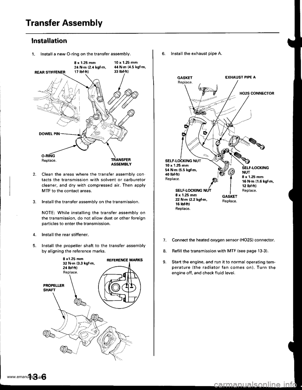
Transfer Assembly
lnstallation
1. Install a new O-ring on the transfer assembly.
8 x 1.25 mm24 N.m (2.4 kgt m,17 rbt.ftl
10 x 1.25 mm44 N.m (4.5 kgJ.m,
2.
DOWEL PIN
Replace.TRANSFEBASSEMBLY
Clean the areas where the transfer assembly con
tacts the transmission with solvent or carburetor
cleaner, and dry with compressed air. Then apply
MTF to the contact areas.
Installthe transfer assembly on the transmission.
NOTE: While installing the transfer assembly on
the transmission, do not allow dust or other foreign
particles to enter the transmission.
lnstall the rear stiffener.
Install the propeller shaft to the transfer assembly
by aligning the reference marks,
8 x1.25 mm32 N.m 13.3 kg{.m,24 tbf.ftl
REFERENCE MARKS
6. Install the exhaust pipe A,
GASKETEXHAUST PIPE A
HO2S CONNECTOR
10 x 1 .25 mm54 N.m (5.5 kgt m,40 tbtfttReplace.
SELF.LOCKING
NUT8 x 1.25 mm16 N.m {1.6 kgf.m,12 tbt.ft)Replace.8 x 1.25 mmzzN.m l2.2kg!-m,16 rbf.trtReplace.
7.Connect the heated oxygen sensor (HO2S) connector.
Relill the transmission with MTF (see page 13-3).
Start the engine, and run it to normal operating tem-
perature (the radiator tan comes on). Turn the
engine off. and check fluid level.
8.
9.
www.emanualpro.com
Page 446 of 1395
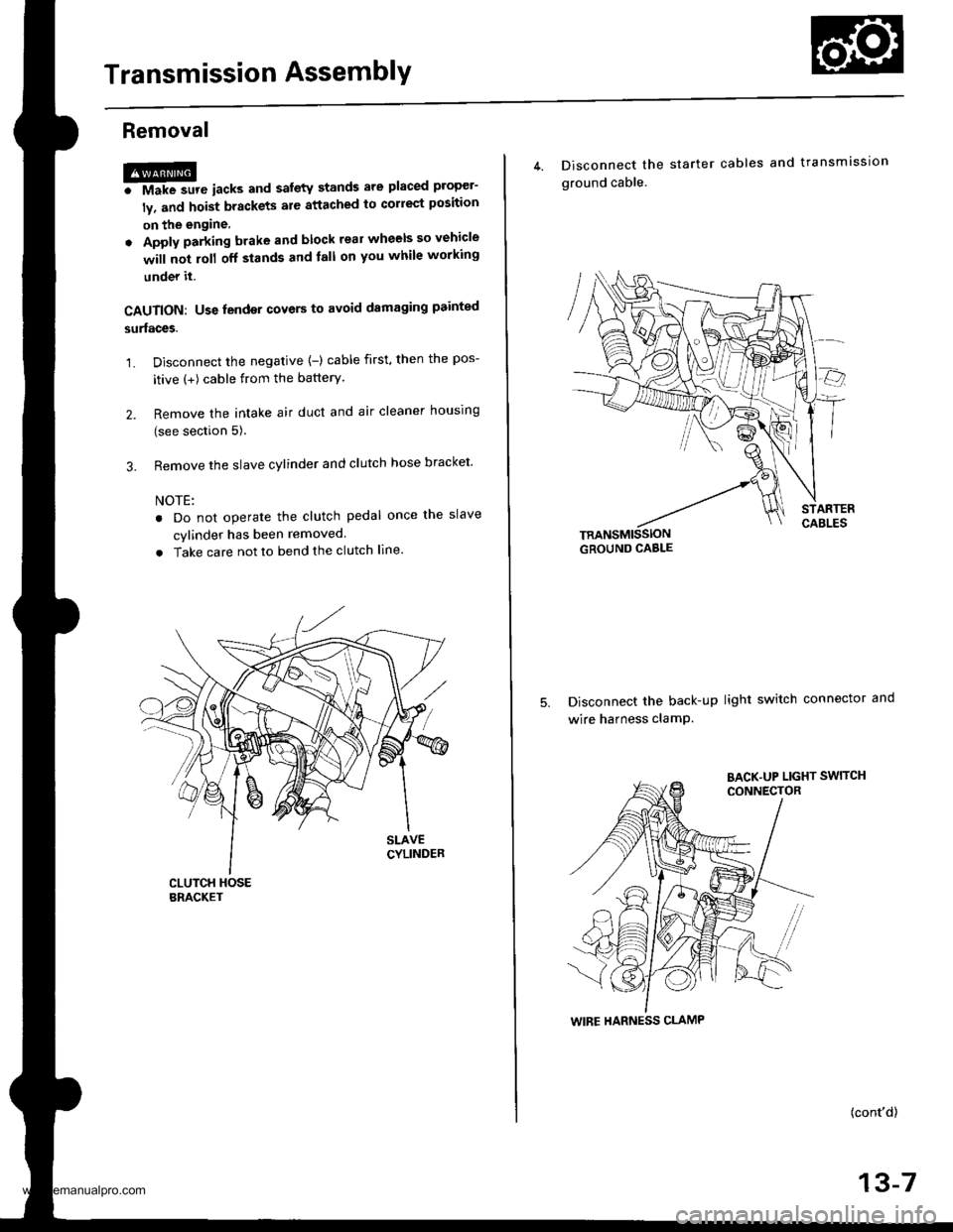
Transmission AssemblY
Removal
@FMak. sw. iack" and safety stands are placed propel-
ly, and hoist brackets are attached to collect position
on the engine,
. Apply parking brake and block rear wheels so vehicle
will not roll off stands and lall on you while working
under it.
CAUTION: Use fender covers to avoid damaging painted
surfaces.
1. Disconnect the negative {-) cable first, then the pos-
itive (+) cable from the batterY.
2. Remove the intake air duct and air cleaner houslng
(see section 5).
3. Remove the slave cylinder and clutch hose bracket'
NOTE:
. Do not operate the clutch pedal once lhe slave
cvlinder has been removed.
. Take care not to bend the clutch line.
4. Disconnect the
ground cable.
starter cables and transmission
TRANSMISSIONGROUND CABLE
Disconnect the back-up light switch connector and
wire harness clamP.
(cont'd)
13-7
WIRE HARNESS CLAMP
www.emanualpro.com
Page 454 of 1395
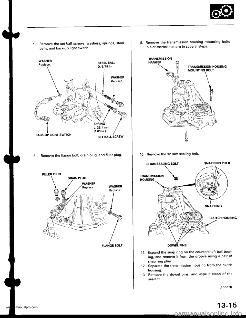
7. Remove the set ball screws, washers, springs, steel
balls. and back-uP light switch.
STEEL BALLD. 5/16 in
8. Remove the flange bolt. drain plug, and filler plug
DRAIN PLUG
WASHERReplace.
LIGHT SWITCH
FILLER PLUG
WASHERReplace.
FLANGE BOLT
9. Remove the transmission housing mounting bolts
in a crisscross pauern in several steps.
10. Remove the 32 mm sealing bolt
Expand the snap ring on the countershaft ball bear-
ing, and remove it from the groove using a pair of
snap ring plier.
Separate the transmission housing from the clutch
housing.
Remove the dowel pins, and wipe it clean of the
sealant.
'I t.
(cont'd)
13-15
www.emanualpro.com
Page 455 of 1395
Transmission Assembly
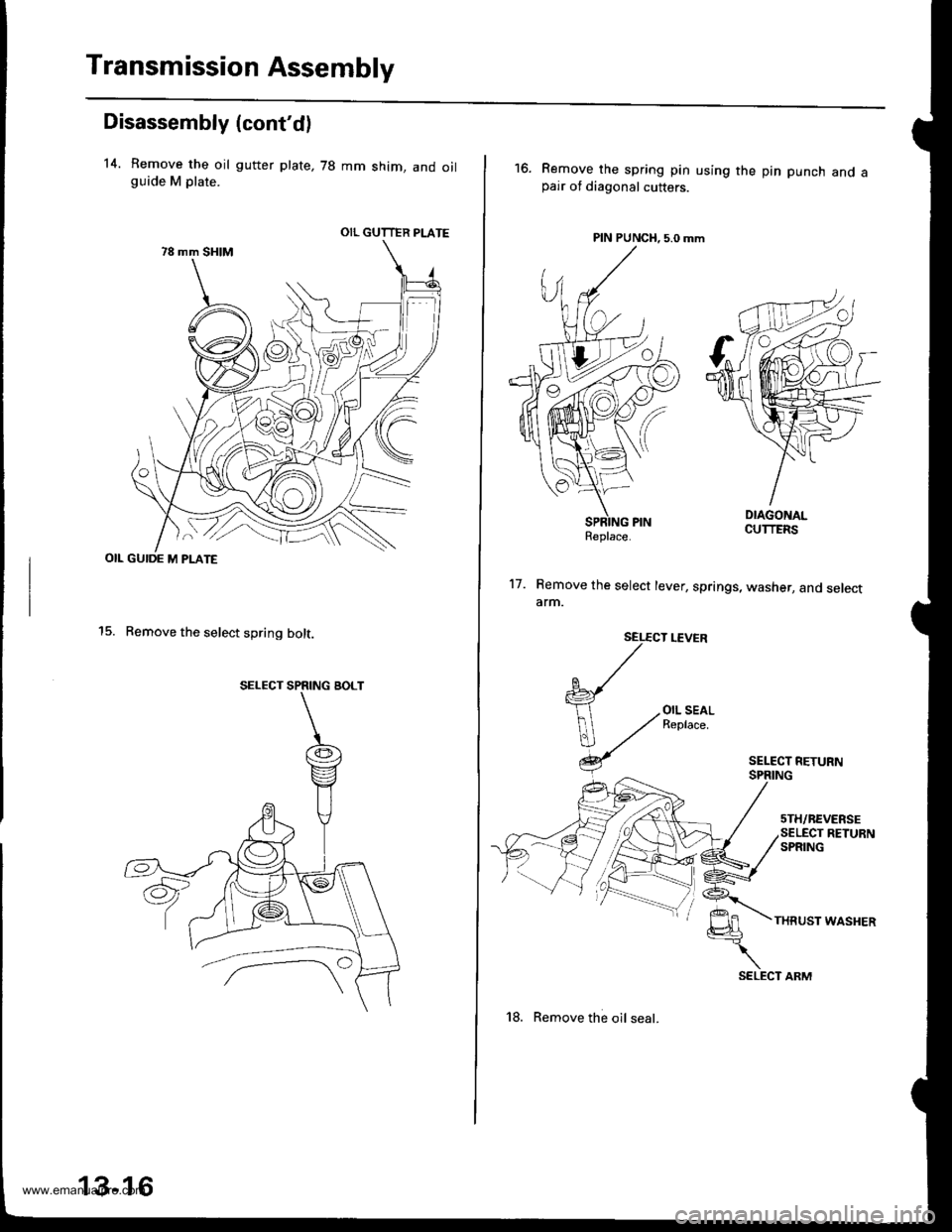
Disassembly (cont'dl
14. Remove the oil gutter plate, 78 mm shim, and oilguide M plate.
OIL GUIDE M PLATE
15. Remove the select spring bolt.
OIL GUTTER PLATE
SELECT SPRING BOLT
13-16
18. Remove the oil seal.
16.Remove the spring pin using the pin punch and apair of diagonal cutters.
PIN PUNCH, 5.0 mm
17. Remove the select lever, springs, washer, and selectarm.
SEL€CT LEVER
{
V
OIL SEALReplace.
THRUST WASHER
Replace.
SELECT ARM
www.emanualpro.com
Page 515 of 1395
Transmission Assembly
Installation (cont'dl
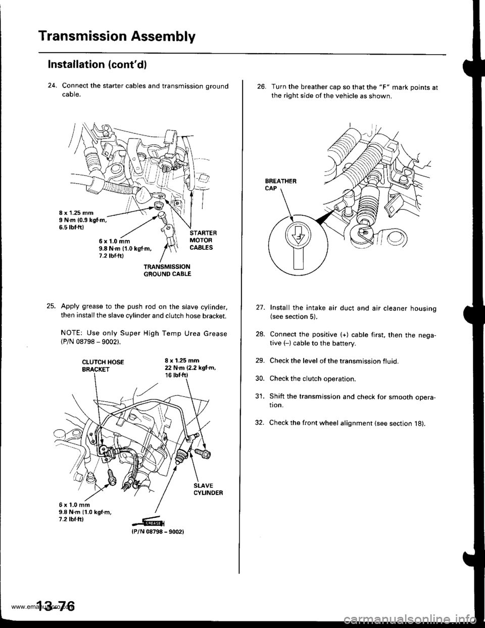
24. Connect the starter cables and transmission ground
caore.
TRANSMISSIONGROUND CABLE
Apply grease to the push rod on the slave cylinder,
then install the slave cylinder and clutch hose bracket,
NOTE: Use only Super High Temp Urea Grease
{P/N 08798 - 9002).
CI-UTCH HOSEBRACKET
8 x 1.25 mm22 N.m 12.2 kgi-m,16 tbr.f0
6x1.0mm9.8 N.m {1.0 kgf.m,7.2 rbf.ftt_G1(P/N 08798
6x1.0mm9.8 N.m (1.0 kg{.m,7.2 tbt.ttl
13-76
- 9002)
26. Turn the breather cap so that the "F" mark points at
the right side of the vehicle as shown.
27. Install the intake air duct and air cleaner housing(see section 5),
28. Connect the positive (+) cable first. then the nega-
tive (-) cable to the battery.
29. Check the level of the transm ission f lu id.
30. Check the clutch operation.
31. Shift the transmission and check for smooth opera-tion.
32. Check the front wheel alignment (see section l8).
www.emanualpro.com