ignition wire HONDA CR-V 1997 RD1-RD3 / 1.G Workshop Manual
[x] Cancel search | Manufacturer: HONDA, Model Year: 1997, Model line: CR-V, Model: HONDA CR-V 1997 RD1-RD3 / 1.GPages: 1395, PDF Size: 35.62 MB
Page 1325 of 1395
Troubleshooting
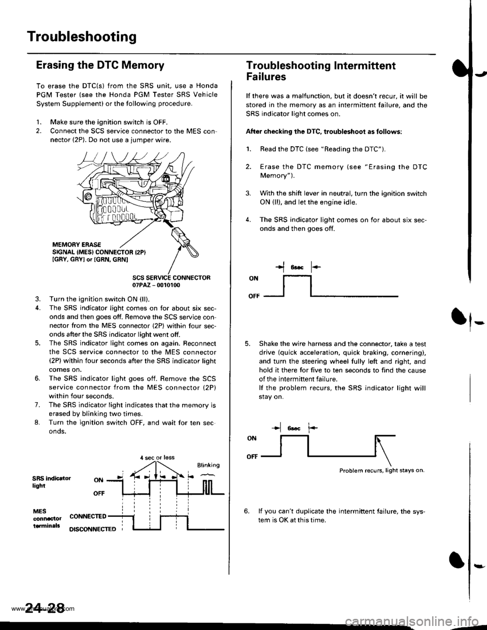
Erasing the DTC Memory
To erase the DTC{S) from the SRS unit, use a Honda
PGM Tester (see the Honda PGM Tester SRS Vehicle
System Supplement) or the following procedure.
1. Make sure the ignition switch is OFF.
2. Connect the SCS service connector to the MES con,
nector (2P). Do not use a jumper wire.
MEMORY ERASESIGNAL (MES} CONNECTOR I2PIIGRY, GRYI or IGRN, GRNI
SCS SERVICE CONNECTOR07PAZ - 0010100
3. Turn the ignition switch ON (ll),
4. The SRS indicator light comes on for about six sec-
onds and then goes off. Remove the SCS servjce con
nector from the MES connector {2P) within four sec-
onds after the SRS indicator light went otf.
5. The SRS indicator light comes on again. Reconnect
the SCS service connector to the MES connector(2P) within four seconds after the SRS indicator lioht
comes on,
6. The SRS indicator light goes otf. Remove the SCS
service connector from the MES connector (2P)
within four seconds.
7. The SRS indicator light indicates that the memory is
erased by blinking two times.
L Turn the ignition switch OFF, and wait for ten sec
onos.
SRS indicatorliqtfi
MESconnac'lolterminals
OFF
CONNECTED
OISCONNECTEO
24-28
,l sec or less
3.
Troubleshooting Intermittent
Failures
lf there was a malfunction. but it doesn't recur, it will be
stored in the memory as an intermittent failure, and the
SRS indicator light comes on.
After checking the DTC, troubleshoot as follows:
1. Read the DTC (see "Reading the DTC").
4.
Erase the DTC memory (see "Erasing the DTC
Memory").
With the shift lever in neutral, turn the ignition switch
ON (ll), and let the engine idle.
The SRS indicator ljght comes on for about six sec-
onds and then goes off.
t*F
ON
lt--- _l
Shake the wire harness and the connector, take a test
drive (quick acceleration, quick braking, cornering),
and turn the steering wheel fully left and right, and
hold it there for five to ten seconds to find the cause
of the intermittent failure.
lf the problem recurs, the SRS indicator light will
stay on.
-+t 6!.c l.-
Problem recurs, light stays on.
6. lf you can't duplicate the intermiftent tailure, the sys-
tem is OK at this time.
:-
-4
www.emanualpro.com
Page 1331 of 1395
Troubleshooting
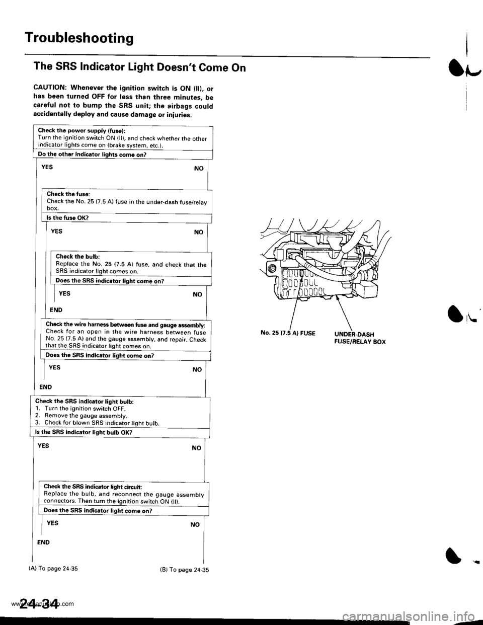
The SRS Indicator Light Doesn't Come On
CAUTION: Whenever the ignition switch is ON D, orhas been turned OFF for less than three minutes, becareful not to bump the SRS unit; the airbags couldaccidentally deploy and cause damage or iniuries.
Ch6ck the power supply (fuse):Turn the ignition switch ON {ll), and check whether the otherindicator lights come on (brake system, e(c.r.
Do the other indicator liglrts com6 on?
Check the No. 25 (7.5 A) fuse in the under-dash tuse/relayDOX.
ls the tus€ oK?
NO
Check the bulb:Replace the No.25 (7.5 A) fuse, and check that theSRS indicator light comes on.
Does the SRS indicator liqht come on?
YESNO
END
YES
Check the wire h.rnesi kwe€n fus€.nd gauge .3sembly:Check for an open in the wire harness between fuseNo. 25 (7.5 Al and the gauge assembly, and repair. Checkthat lhe SRS indicato.lighi
Does the SRS indic.tor liqht com6 on?
END
YESNO
Check the SRS indicator light bulb:1. Turn the ignition switch OFF.2. Remove the gauge assembly.3. Check lor blown SRS indicator tight bulb.
ls the SRS indicator tight bulb OK?
YESNO
Check the SRS indicator light circuit:Replace the bulb, and reconnect the gauge assemblyconneclors. Then turn the ignition switch ON {ll).
Does the SRS indicator light come on?
I YEs No
:ND
(A) To page 24-35(B) To page 24 35
24-34
lr-
lu
-J
www.emanualpro.com
Page 1332 of 1395
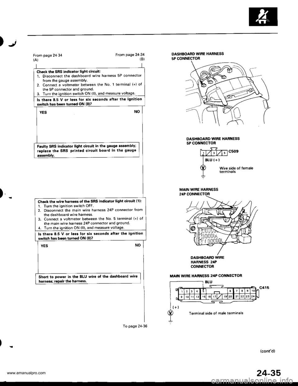
Chock th6 SRS indic.lor light circuit:1. Disconnect the dashboard wire harness 5P connector
from the gauge assembly.2. Connect a voltmeter between the No l terminal (+) o{
the 5P connector and grouncl.
3. Turn the ignition switch ON {ll), and measure voltage
ls thero 8.5 V or lats for 3ix second! aflsr the ignition
switch ha3 bo€n turnod ON (ll)7
YESNO
Fdulty SRS indicator light cilctlit in ths gauge sssomblY;
replaco tho SRS printod circuit board in the gauge
aasombly,
Chock th6 wire harn.$ of the SRS indicstor light circuh (11:
1. Turn the ignition switch OFF.2. Disconnect the main wire harness 24P connector from
the dashboard wire harness-3. Connect a voltmeter between the No 5 terminal (+) of
the ma;n wire harness 24P connecior and ground
4. Turn the ignition ON {ll), and measure voltage.
ls there 8,5 V or l€r3 tor six s€cond3 efter the ignilion
switch has bssn turnod ON llll?
YESNO
Short to powor in the BLU wire of tho dashbosrd wire
harne3s; Epait the harne3.s.
To page 24-36
Jt)
From page 24 34(A)From page 24-34(8)DASHBOARD WIRE HARNESS
5P CONNECTOR
DASHBOARD WIRE HARI{ESS5P CONI{ECTOR
c509
Wire side ol femaleterminals
)_
DASHBOARO WIREHARNESS 24PCONNECfOR
(cont'd)
MAIN WIRE HARNESS
MAIN WIRE HARI{ESS 2/tP COI{ ECTOR
Terminal side of male terminals
24-35
www.emanualpro.com
Page 1333 of 1395
Troubleshooting
From page 24-35
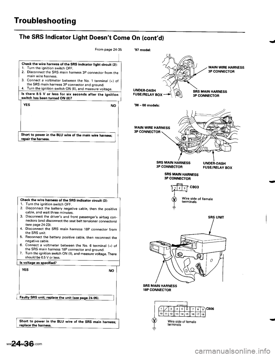
Check lhe wire harness otthe SRS indicator light circuit l2l:L Turn the ignitjon switch OFF.2. Disconnect the SRS main harness 3p connector from themain wire harness.3. Connect a voltmeter between the No. I terminal (+) ofthe SRS main harness 3P connector and qround.4. Turn the ignition switch ON (ll), and measure voltaqe.
ls there 8.5 V o. less tor six seconds atter the ignitionswitch has been turned ON
Short to power in th€ BLU wire of the main wiro halno3s;
Check th€ wire hahess of th6 SRS indicator ci.cuit {31:1. Turn the ignition switch OFF.2. Disconnect the battery negative cable, then the positivecable, and wait three minutes.3. Disconnect the driver's and front passenger,s airbag con-nectors {and disconnect the seat belt tensioner connectors}(see page 24-23).4. Disconnect the SRS main harness 18p connector from
5. Reconnect the battery positive cable, then reconnect thenegative cable.6. Connect a voltmeter between the No. 6 terminal (+) ofthe SRS main harness 'l8P connector and ground.7. Turn the ignition switch ON (ll), and measure voltage. Thereshould be 0.5 V or less.
Short to power in the BLU wire oI the SRS main harngas;
The SRS Indicator Light Doesn't Come On (cont,dl
'97 modol:
J
MAIN WIRE HARNESS3P CONNECTOR
UNDER.DASHFUSE/RELAY BOX
'98 - 00 models:
SRS MAIN HARN€SS3P CONNECTOR
MAIN WIRE HARNESS3P CONNECTOR
SRS MAIN HARNESS3P CONNECTOR
SRS MAIN HARNESS3P COI{NECTOB
FUSE/RELAY BOX
c803
SRS MAIN HARNESS18P CONNECTOR
24-36
www.emanualpro.com
Page 1336 of 1395
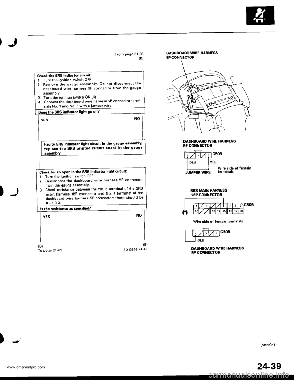
Check lhe SRS indicalor circuit:
1. Turn the ignition switch OFF
2. Remove the gauge assembly Do not disconnect the
dashboard wire harness 5P connector from the gauge
assemoly.3. Turn the ignition switch ON (ll).
4. Connect tie dashboard wire harness 5P connector termi-
nals No. I and No 5 with a iumper wire.
Does the SRS indicator light 90 otn
Faulty SRS indicator light circuit in the 9aug6 a$embly;
reolace the SRS printod circuit boa.d in th' gauge
Check tor rn open in the SRS indicator light circuit:
1. Turn the ignition switch OFF
2. Disconnect the dashboard wire harness 5P connector
from the gauge assemblY.
3. Check res]sta-nce between the No. 6 terminal ol the SRS
main harness 18P connector and No l terminal ol the
dashboard wire harness 5P connector; there should be
From page 24-38{B)
DASHBOARD WIRE HARNESS5P CONNECTOR
DASHBOARD WIRE HARNESS5P CONI{ECTOR
)
Y;yfivvcsosffi
I BLU IYELWir6.side of femaleJUMPER WIRE lormrna|s
SRS MAI HAN ESSt8P CO I{ECTOR
DASHBOARD WIRE HARNESS5P COI{NECTOR
{D)To page 24-41
1E)To page 24-41
)(cont'd)
Wire side oI fsmale terminals
24-39
www.emanualpro.com
Page 1338 of 1395
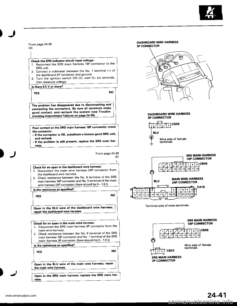
)
From page 24-39(D)
DASHBOARD wlRE hARNESS
5P CONNECTON
DASHBOARO WIRE HARI{ESS
5P CONI{EC'OR
)From page 24-39iE)
c509
Terminal side of male lerminals
SRS MAIN HABN€SS3P CONNECTOR
)
Check the SRS indicator circuit input voltage:
1. Reconnect the SRS main harness 18P connector to the
SRS unit2. Connect a voltmeter between the No 1 terminal (+) of
the dashboard 5P connector and ground.
3. Turn the ignition switch ON (ll), wait for six seconds,
then measure voltage
fs there 8.5 V or more? -
YESNO
The oroblem hts disappoared due to disconnocting and
connecting the connectors. Be 3ure all terminals make
good contact, and rocheck the system {see Trouble'
shooting Intermittent Failur6 on pagg 2'l-281'
Pool contacl at the SRS main harness 18P connector; check
the connector.. lf the connoctor is OK. aubstituta a known-good SRS unit,
and recheck.. ll the problem is still present, replaco the SRS main h'r-
ness.
Check for an oPen in the dashboard wire hatn8s:
1. Disconnect the main wire harness 24P connector Irom
the dashboard wire harness
2. Check resistance between the No. 6 terminal of the SRS
main hamess 18P connector and No 5 terminal otthe main
wire harness 24P connector; there should be 0- 1 0 O
15 the resistance.s specified?
YESNO
ODen in the BLU wire ot the dashboard wit6 harness;
rep.ir the dashboald wite harness.
Check for an open in the main wirc harness:'1. Disconnect the SRS main harness 3P connector from the
main wire harness,2. Check resistance between the No. 6 terminal of the SRS
main harness 18P connector and No 1 terminal ofthe SRS
main harness 3P connector;there should be 0 - 1 0 u
|3 lhe re3istance as sPecifiod?
YESNO
Oo€n in the BLU wire ol the main wire harness; rcpair
tha main wire harness
Op€n in the SRS main harn4s; replace the SRS msin har'
no3s.
24-41
www.emanualpro.com
Page 1340 of 1395
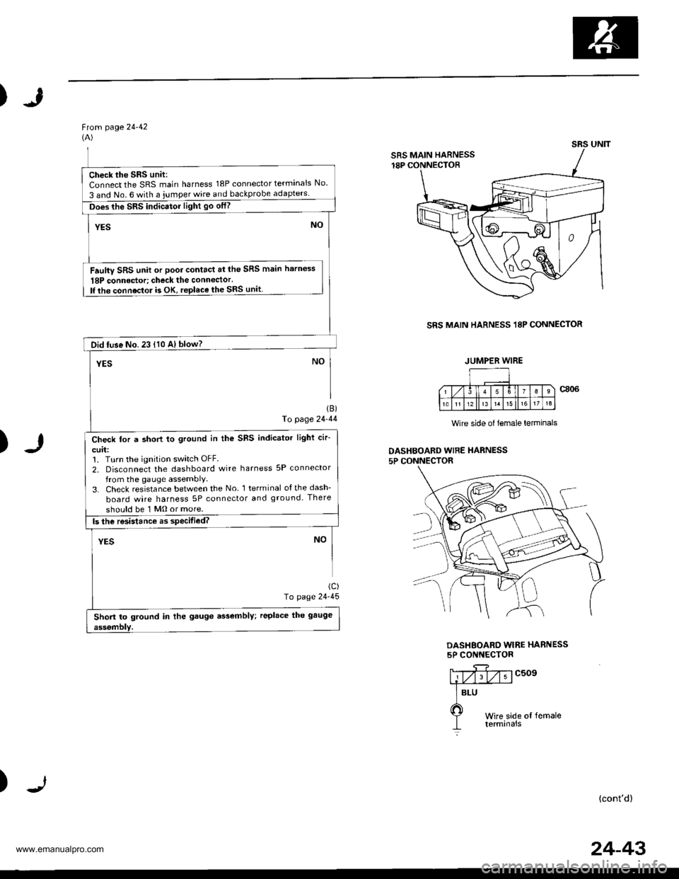
)
Ftom page 24-42(A)
SRS MAIN HARNESS 18P CONNECTOR
)
1B)fo page 24-44
(c)
To page 24-45
Wire side of lemale lerminals
DASHBOAED WIRE HARNESS5P CONNECTOR
DASHEOARD WIRE HARNESS5P CONNECTOR
c509
)(cont'd)
SRS UNIT
SRS MAIN HARNESS
Check the SRS unit:Connect the SRS main harness 18P connector terminals No.
3 and No. 6 with a iumper wire and backprobe
Does the SRS indicator light go otf?
Faulty SRS unit or poor contact at the SRS main harness
18P connedor; check the connector.lf the connoctor is OK, replace the SRS unit
Did tuse No. 23 {10 A} blow?
Check for a short to ground in the SRS indicator light cir-
curl:1. Turn the ignition switch OFF.
2, Disconnect the dashboard wire harness 5P connector
from the gauge assembly,3. Check resistance between the No l terminal ofthedash-
board wire harness 5P connector and ground. There
should be 1 Mo or more.
Short to ground in the gauge assembly; replace the gauge
JUMPER WIRE
24-43
www.emanualpro.com
Page 1341 of 1395
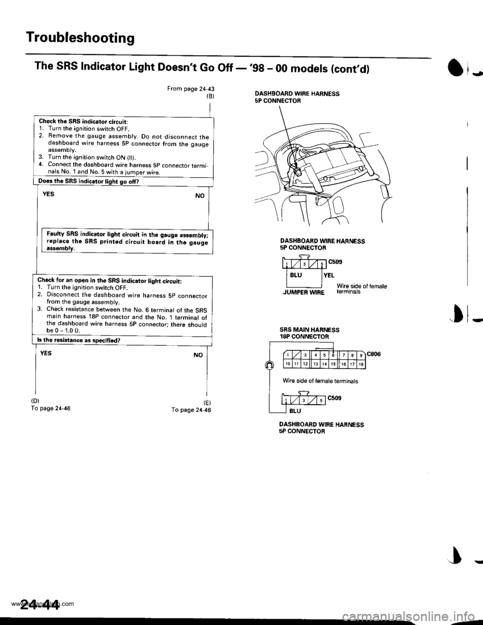
Troubleshooting
The SRS Indicator Light Doesn't Go Off -'99 - 00 models (cont,d)
From page 24,43DASHBOARD WIRE HARNESS5P CONNECTOR(B)
Check the SRS indicator circuit:1. Turn the ignition switch OFF.2. Remove the gauge assembly. Do not disconnect thedashboard wire harness 5p connector trom the gaugeassemDty.3. Turn the ignition switch ON 0l).4. Connect the dashboard wire hamess 5p connector terminals No. 1 and No. 5 with a iumoer wire.
Doos lhe SRS indic.tor light go offl
YESNO
Fauhy SRS indic.tor light circuit in lho gruge a3samblv;replaco the SRS print6d circuit bo.rd in the g.ugeassombly.
Check for an opeo in the SRS indicaior light circuit:1. Turn the ignition swirch OFF.2. Disconnect the dashboard wire harness 5p connectorfrom the gauge assembly.3. Check resistance between the No. 6 terminal of the SRSmain haroess 18P connector and the No. 1 terminal otthe dashboard wire harness 5P connector; there shouldbe0-1.0O.
|3 the rosbtance a3 sDecified?
YESNO
(D)
To page 24-46(E)To page 24-46
DASHBOARD WIRE HARNESS5P CONNECTOR
J
DASHBOARD WIRE HANNESS5P CONNECTOR
liTv;Tv;1c5i0s#
lsru lYErWire sade ol lernaleJUMPER w|RE rerminats
I
SRS MAIN HARNESS18P CONNECTOR
J
Wir€ side ot lemale ieminals
24-44
,-
www.emanualpro.com
Page 1343 of 1395
Troubleshooting
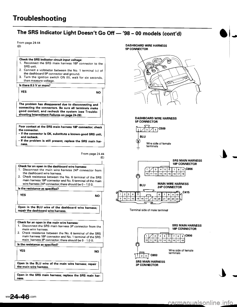
The SRS Indicator Light Doesn't Go Off -,99 - 00 models (cont,d)
Frcm page 24-44{D)
Ch€ck the SRS indicator circuit input voltage:1. Reconnect the SRS main harness 18p connector to theSRS unit.2. Connect a voltmeter between the No. 1 terminal {+) ofthe dashboard 5P connector and ground.3. Turn the ignition switch ON {ll}, wait for six seconds,then measure voltage.
ls there 8.5 V or more?
YESNO
The problem has disapp€ared due to disconnecting andconnecting tho connectors. Be sure all terminals makegood contact, and .echeck the system {seo Troublo_shooting Intermiftent Failures on page 2it-2E).
Poo. contact at the SRS main harn8s 18p connector; checkthe connector.. lf the connoctor is OK, aubstitute a known-good SRS unit,end recheck.. lf the problem is still present, .6place tho SRS m.in har-ne33.
Ftom lage24-44(E)
J)
DASHEOARD WFE HARNESS5P CONNECTOR
c5ott
Wire side of lemaleterminals
J
Torminal side ol male termtnal
ca03
SRS MAIN HARNESS18P CONNECTOR
c806
SRS MAIN HARNESS3P CONNECTOR
DASHBOARD WIRE HARNESS
Check for an open in the dashboa.d wire harnessi1. Disconnect the main wire harness 24p connector fromthe dashboard wire harness.2. Check resistance between the No. 6 terminal of the SRSmain harness 18P connector and No. S te.minal of the mainwire harness 24P connector; there should be 0 - 1.0 0.
ls th€ resistance rs speciliedT
YESNO
Open in the 8LU wi.o ol the dashboard wire hrmess:repair the dashboard wire ha.ness.
Check fo. an open in the m.in wire hamess:1. Disconnect the SRS rnain harness 3p connector from themain wire harness,2. Check resistance between the No. 6 terminal of the SRSrnain harness 18P connector and No. 1 terminal of the SRSmain harness 3P connector;there should be 0 1.0O.
b the rGbtanco as sDecified?
NOYES
Open in the BLU wir6 of th6 main wire hernos3; reori.the main wire hamess,
Open in the SRS main harness; r€place the SRS main ha.-noss.
24-46
--
www.emanualpro.com
Page 1363 of 1395
Troubleshooting
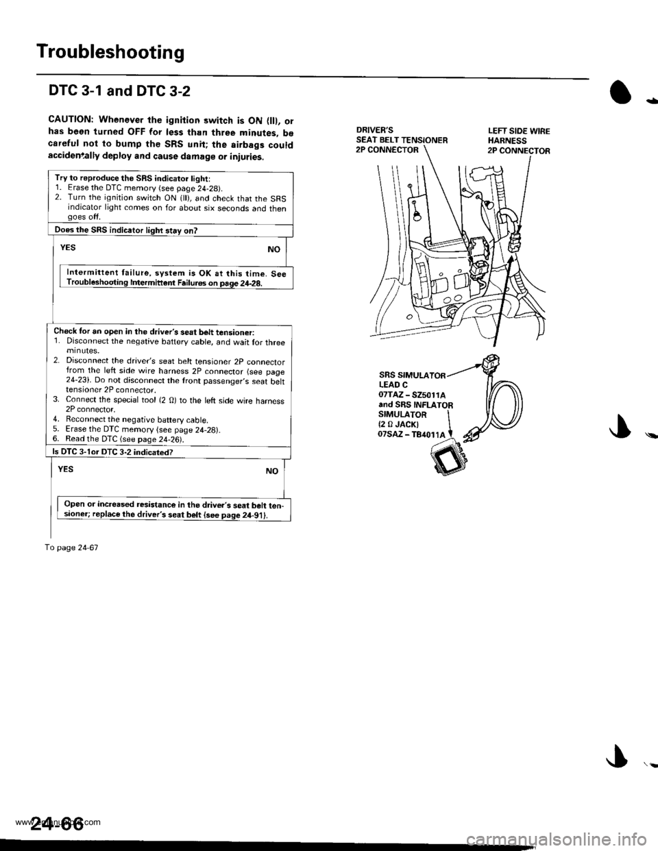
DTC 3-1 and DTC 3-2
CAUTION: Whenever the ignition switch is ON flll, orhas been turned OFF for less than three minutes, b€careful not to bump th€ SRS unit; the airbags couldaccidenlally deploy and cause damage or iniuries.
DRIVER'SSEAT BELT TENSIONERLEFT SIOE WIREHARNESS2P CONNECTOR2P CONNECTOR
-
\
SRS SIMULALEAD C07TAZ - SZ501rAand SRS INFLATORSTMULAToR It2 0JACKI IoTsaz - TB4ot lA t
24-66
Try to reproduce the SRS indicatoi light:1. Erase the DTC memory (see page 24-29).2. Turn the ignition switch ON 1 ), and check that the SRSindicator light comes on for about six seconds and thengoes off.
Does the SRS indicaior lighr stay on?
YESNO
Intermittent failure, system is OK at this time. SeeTroubleshooting lfiermittent Failu.6s on page 24-28.
Check tor an open in the driver's seat b6lt tensioner:1. Disconnect the negative battery cable, and wait lor threeminutes.2. Disconnect the drave/s seat belt tensioner 2p connectorfrom the left side wire harness 2P connector (see page24-23). Do not disconnect the lront passenger,s seat belttensioner 2P connector.3. Connect the special tool {2 O) to the left side wire harness2P connector,4. Reconnect the negative baftery cable5. Erase the DTC memory {see page 24,28).6. Read the DTC (see page 24-26).
ls OTC 3-1or DTC 3-2 indicatedT
YESNO
Open or increased resistance in the d.iver's seat belt ten-sioner; replace the driver's seat belt {see page 2il-91).
To page 24 67
www.emanualpro.com