Egr HONDA CR-V 1997 RD1-RD3 / 1.G User Guide
[x] Cancel search | Manufacturer: HONDA, Model Year: 1997, Model line: CR-V, Model: HONDA CR-V 1997 RD1-RD3 / 1.GPages: 1395, PDF Size: 35.62 MB
Page 780 of 1395
Transmission
Cooler Flushing
@@ To prevent in;ury to face and eyos, atwayswear safety glasses ot a face shield when using thetlansmission flusher.
This procedure should be performed before reinstallingthe transmission.
2.
LCheck equipment for wear and cracks before using.Replace any worn or cracked components.
Using the measuring cup. fill the tank with 21 ounces{approximately 213 lull) ol biodegradable flushingfluid (J35944 - 20). Do not substitute with any otherfluid. Follow the handling procedure on the fluidcontaaner.
Secure the flusher filler cap, and pressurize theflusher with compressed air to 550 - 829 kpa (5.6 _
8.45 kgf/cm,, 80 - 120psi). The air line should beequipped with a water trap to ensure a dry air sys-tem.
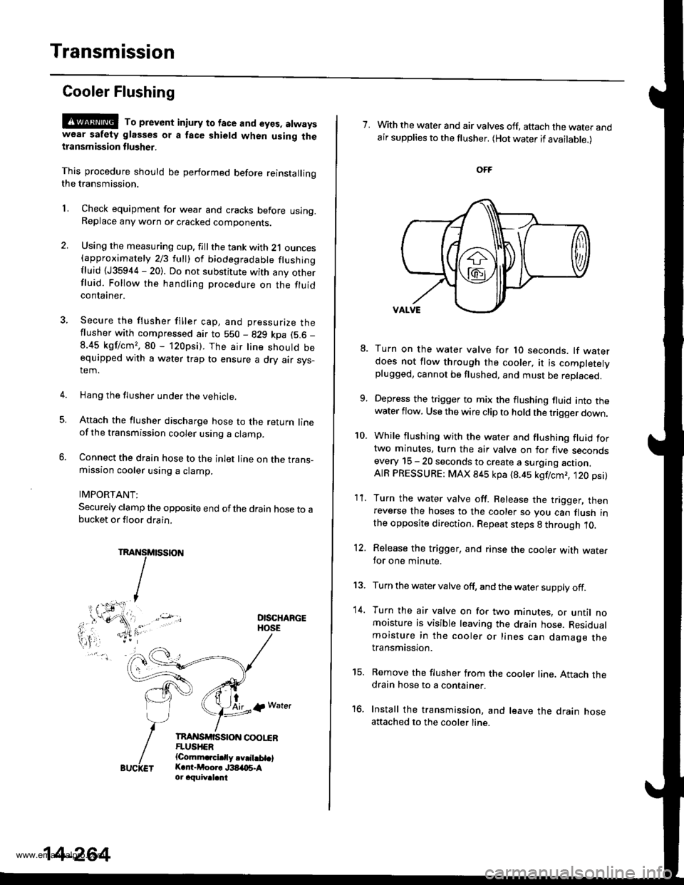
Hang the flusher under the vehicle.
Attach the flusher discharge hose to the return lineof the transmission cooler using a clamp.
Connect the drain hose to the inlet line on the trans-mission cooler using a clamp.
IMPORTANT:
Securely clamp the opposite end ofthe drain hose to abucket or floor drain.
DISCHARGEHOSE
tAirlp Water
TnAI{SrfiSStoN coot"€RFLUSHER{Comm.rcidly.v.il.bt.lK.r -Moor. J38,t{15.Aor aquival.nt
5.
14-264
7. With the water and air valves off, attach the water andair supplies to the flusher. (Hot water if available.)
10.
8.
1'�I.
Turn on the water valve for 1O seconds. lf waterdoes not flow through the cooler, it is completelyplugged, cannot be flushed, and must be replaced.
Depress the trigger to mix the flushing fluid into thewater flow. Use the wire clip to hold the trigger down.
While flushing with the water and flushing fluid fortwo minutes, turn the air valve on for five secondsevery 15 - 20 seconds to create a surging action.AIR PRESSURE: MAX 845 kpa (8.45 kgf/cmr, t20 psi)
Turn the water valve off. Release the trigger, thenreverse the hoses to the cooler so you can flush inthe opposite direction. Repeat steps 8 through 10.
Release the trigger, and rinse the cooler with wate.for one minute.
Turn the water valve off, and the water supply off.
Turn the air valve on for two minutes, or until nomoisture is visible leaving the drain hose. Residualmoisture in the cooler or lines can damage thetransmission.
Remove the flusher from the cooler line. Attach thedrain hose to a container.
Install the transmission, and leave the drain hoseattached to the cooler line.
12.
13.
14.
to.
www.emanualpro.com
Page 794 of 1395

Description
Rear Differential
Outline
The Real-time 4WD-Dual Pump System model has a hydraulic clutch and a differential mechanism in the rear differential
assembly. Under normal conditions, the vehicle is driven by the front wheels. However, depending on to the driving force
of the front wheels and the road conditions. the system instantly transmits appropriate driving force to the rear wheels
without requiring the driver to switch between 2WD (tront wheel drive) and 4WD (four wheel drive). The switching mecha-
nism between 2WD and 4WD is integrated into the rear differential assembly to make the system light and compact.
ln addition, the dual-pump system switches off the rear-wheel-drive force when braking in a forward gear. This allows the
braking system to work properly on models equipped with an Anti-lock Braking System (ABS).
Construction
The rear differential assembly consists of the torque control differential case assembly and the rear differential carrier
assembly. The torque control differential case assembly consists of the differential clutch assembly, the companion
flange, and the oil pump body assembly. The rear differential carrier assembly consists of the differential mechanism. The
differential drive and driven gears are hypoid gears.
The oil pump body assembly consists of the front oil pump, the rear oil pump, the hydraulic control mechanism, and the
clutch piston. The clutch piston has a disc spring that constantly provides the differential clutch assembly with a preset
torque to Drevent abnormal sound.
The clutch guide in the differential clutch assembly is connected to the propeller shaft via the companion flange, and it
receives the driving force lrom the transfer assembly. The clutch guide rotates the clutch plate and the front oil pump in
the oil pump body.
The clutch hub in the differential clutch assembly has a clutch disc that is splined with the hypoid drive pinion gear. The
hypoid drive gear drives the rear oil pump.
The front and rear oil pumps are trochoidal pumps. The rear oil pump capacity is 2.5 percent larger that the front oil pump
to handle the rotation difference between the front and rear wheels caused by worn front tires and tight corner braking.
The oil pumps are designed so the fluid intake works as a fluid discharge when the oil pumps rotate in reverse. Genuine
Honda CVT fluid is used instead of differential fluid.
Operation
When there is a difference in rotation speed between the front wheels (clutch guide) and rear wheels (hypoid driven gear),
hydraulic pressure from the front and rear oil pumps engages the differential clutch, and drive force from the transler
assembly is applied to the rear wheels.
The hydraulic pressure control mechanism in the oil pump body selects 4WD mode when the vehicle is started abruptly,
or when accelerating in a forward or reverse gear (causing rotation difference between the front and rear wheels). or
when braking in reverse gear {when decelerating). lt switches to 2WD mode when the vehicle is driven at a constant speed
in forwar! or reverse gear (when there is no rotation difference between the front and rear wheels), or when braking in a
fo rwa rd gear (when decelerating).
To protect the system, the differential clutch assembly is lubricated by hydraulic pressure generated by the oil pumps in
both 4WD and 2WD modes. Also, the thermal switch relieves the hydraulic pressure on the clutch piston and cancels 4WD
mode if the temDerature of the differential fluid rises above normal.
www.emanualpro.com
Page 800 of 1395
Real-time 4WD-Dual Pump System
Troubleshooting (Automatic Transmissionl
When starting and accelerating in forward gesrs {4WDmodel
1. Lift up the vehicle so all four wheels are off theground (see section 1).
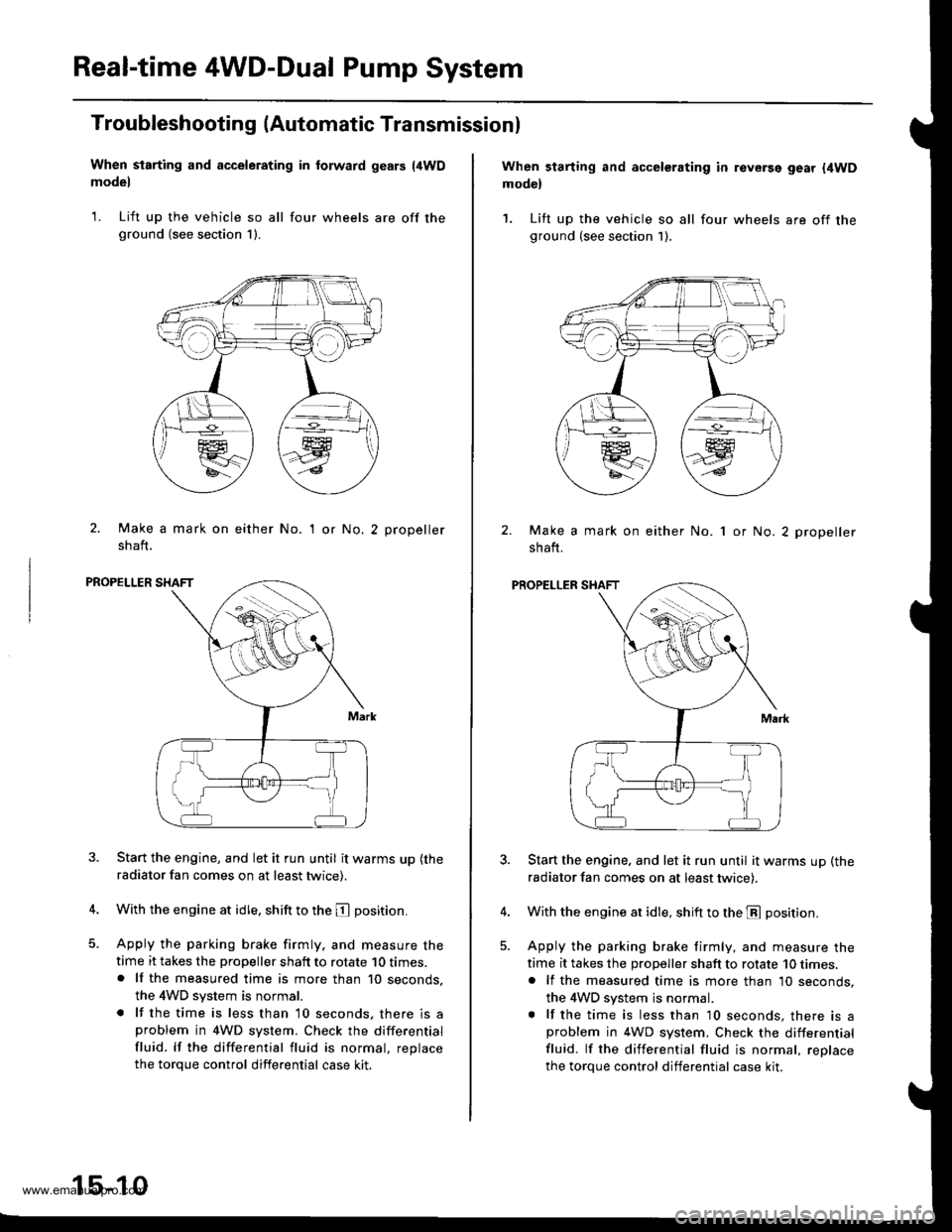
2. Make a mark on either No.
shaft.
'I or No.2 propeller
PROPELLER SHAFT
Start the engine, and let it run until it warms up (the
radiator fan comes on at least twice).
With the engine at idle. shift to the E position.
Apply the parking brake firmly. and measure thetime it takes the propeller shaft to rotate 10 times.. lf the measured time is more than 10 seconds,
the 4WD system is normal.
. lf the time is less than 10 seconds, there is aproblem in 4WD system. Check the differential
fluid. lf the differential fluid is normal, replace
the torque control differential case kit.
15-10
When starting and accelerating in revGrsg gear {4WDmodel
1. Lift up the vehicle so all four wheels are off theground (see section 1).
Make a mark on either No.
shaft.
1 or No. 2 propeller
PROPELLER SHAFT
Start the engine. and let it run until it warms up (the
radiator fan comes on at least twicei.
With the engine at idle, shift to the E position.
Apply the parking brake firmly, and measure the
time it takes the proDeller shaft to rotate 10 times,. lf the measured time is more than 10 seconds,
the 4WD system js normal.. lf the time is less than 10 seconds, there is aproblem in 4WD system. Check the differential
fluid. lf the differential fluid is normal, reolace
the torque control differential case kit.
www.emanualpro.com
Page 826 of 1395
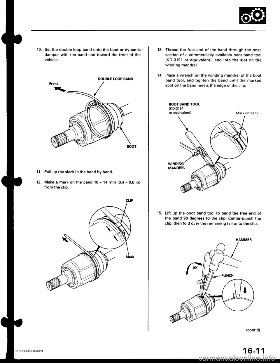
10. Set the double loop band onto the boot or dynamic
damper with the band end toward the front of the
vehicle.
11. Pull up the slack in the band by hand.
12. Make a mark on the band 10 - 14 mm (0.4 - 0.6 in)
from the clip.
OOUBLE LOOP BAND
CLIP
13.
'14.
Thread the free end of the band through the nose
section of a commercially available boot band tool(KD-3191 or equivalent). and into the slot on the
winding mandrel.
Place a wrench on the winding mandrel of the boot
band tool. and tighten the band until the marked
spot on the band meets the edge of the clip.
BOOT BAND TOOL(KD-3191
or equivalentlMark on band.
15.
WINDINGMANDREL
Lift up the boot band tool to bend the free end of
the band 90 degrees to the clip, Center-punch the
clip, then fold over the remaining tail onto the clip.
(cont'd)
16-1 1
HAMMER
www.emanualpro.com
Page 842 of 1395
13.
14.
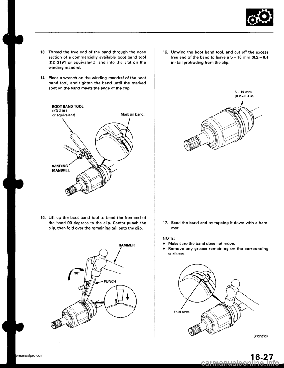
Thread the free end of the band through the nose
section of a commerciallv available boot band tool(KD-3191 or equivalent), and into the slot on the
winding mandrel,
Place a wrench on the winding mandrel of the boot
band tool, and tighten the band until the marked
spot on the band meets the edge of the clip.
BOOT BAND TOOL(KD-3191
or equivalent)Mark on band.
WINDINGMANDREL
Lift up the boot band tool to bend the free end of
the band 90 degrees to the clip, Center-punch the
clip, then fold over the remaining tail onto the clip.
HAMMER
16. Unwind the boot band tool, and cut off the excess
free end of the band to leave a 5 - 10 mm (0.2 - 0.4
in) tail protruding from the clip.
5-10mm(0.2 - 0.4 in)
17. Bend the band end by tapping it down with a ham-
mer.
NOTE:
. Make sure the band does not move.
. Remove any grease remaining on the surrounding
surfaces.
(cont'd)
16-27
www.emanualpro.com
Page 854 of 1395
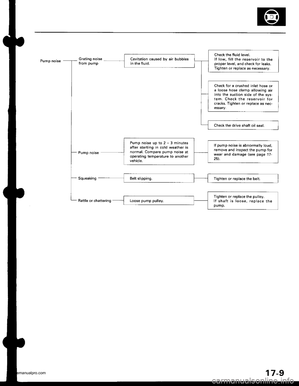
Pump noiseGrating nois€trom pump
Pump noise
Raftle or chattering
Check the fluid lev€1.lt low, fill the reservoir to theproper level. and check for leaks.Tighten or roplace as necessary,
Cavitation caused by air bubblesin the fluid.
Check for a crushed inlet hose ora loose hose clamp allowing airinto the suction side of the system. Check the reservoir forcracks. Tighten or replace as nec-
Check the drive shaft oil seal.
Pump noise up to 2 - 3 minutesafter starting in cold weather isnormal, Compare pump noise atoperatrng temperature to anothervehicle.
ll pump noise is abnormally loud,remove and inspect the pump forwear and damage (see page 17-251.
Tighten or replace the pulley.lI shaft is loose, replace thepump.
17-9
www.emanualpro.com
Page 1168 of 1395
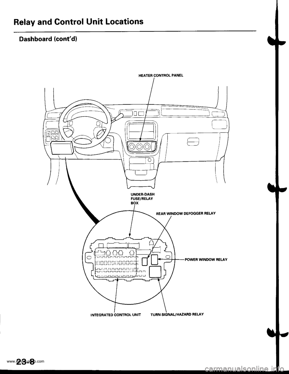
Relay and Gontrol Unit Locations
Dashboard (cont'd)
HEATER CONTROL PANEL
REAR WINDOW DEFOGGER RELAY
WINDOW RELAY
-rj,r1 /-\,r1Iu lJ-JlJ r*t
23-8
INTEGRATEO CONTROL UNITTURN SIGNAL/HAZARD RELAY
www.emanualpro.com
Page 1180 of 1395

Connector ldentification and Wire Harness Routing
Main Wire Harn€ss (left side of dash and floor branchesl {cont,dl
c401
c402
c403
c404
c404
c405
c406
c407
c408
c409
c410
c410
c411
c412
c413
c413
c414
c415
c416
c416
c417
c418
c419
c420
c420
c421
c422
c423
c424
c425
c42A
c426
c437
c438
c438
c439
c440
c441c442
5
20
20
24
't4
8
5
3
12
10'1
18
20'18
10
15
1
4
8
5
5
22
Behind left kick panel
Behind left kick panel
Behind left kick panel
Behind left kick panel
Behind left kick panel
Under left side of dashUnder left side of dashUnder left side of dashUnder left side of dashUnder left side of dashUnder left side of dashUnder left side of dash
Under left side of dashUnder left side of dashUnder left side of dash
Under left side of dash
Under left side of dashUnder left side of dashUnder left side of dashUnder left side of dashUnder left side of dashUnder left side of dashUnder left side of dashUnder left side of dash
Under left side of dashUnder left side of dashUnder left side of dashUnder middle of dashUnder middle of dashUnder middle of dashUnder middle of dashUnder middle of dash
Under left side of dashUnder left side of dash
Under left side of dashUnder left side of dashUnder left side of dashUnder left side of dashUnder left side of dash
Under left side of dash
Under left side of dashUnder left side of dashUnder left side of dashUnder left side of dash
Starter cut relay
Horn relay
Left side wire harness (C558)
Left side wire harness (C559)
Left side wire harness (C559)
Cruise control unitDaytime running lights control unitDaytime running lights control unitlgnition key light control unitInterior wire harness {C701)Cable reel
Cable reel
lgnition key switchlgnition key switch
Combination switch sub-harness {C753)
Combination switch sub-harness (C753)
SRS main harness (C803)
Dashboard wire harness (C503)
Dashboard wire harness (C501)
Dashboard wire harness {C501)Under-dash fuse/relay box (C922)
Under-dash fuse/relay box (C920)
Under-dash fuse/relay box (C919)
lntegrated control unit
Integrated control unitFront fog lights switchBrake switch
Interlock control unitReverse relay
Rear accessory socket relayRear accessory socket relayRear heated oxygen sensor sub-harness (C722)
Security control unitSecurity starter cut relay (for securityalarm system)
Junction connector (for interlock system)Security wire harnessSecurity wire harnessRear window wiper control unitCombination switch sub-harness (C760)
Combination switch sub-harness (C760)
Securlty indicatorSecurity valet switchClutch interlock switchClutch switch (for cruise control)
'97 model'98 - 00mooets
Canada
Canada'97 model
'97 model'98 - 00models
'97 - 98models'99 - 00
moqets
'97 model'98 - 00mooets
Optional
Optional
Optional
Optional
Optional'97 model
'97 - 98mooels'99 - 00models
OptionalOptional
Mfi
Mlr
Under left side of dashBody ground, via main wire harness
23-20
www.emanualpro.com
Page 1201 of 1395
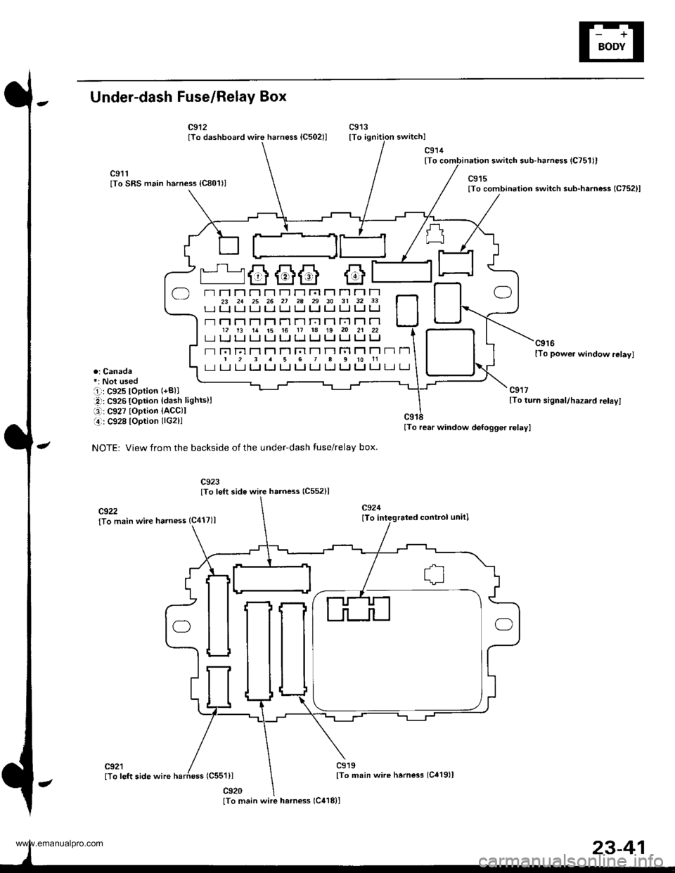
Under-dash Fuse/Relay Box
c912lTo dashboard wire harness {C502ll
a; Canada
i -': C927 loption {ACCll
141: C928 lOption (lG2)l
NOTEr View from the backside of the under-dash tuse/relay box.
c919lTo main wire herness 1C419)l
c914lTo
c924
lTo integraled conttol unitl
lTo rear window defogger relayl
c915lTo combinatioo switch sub-harness 1C752)l
c9r 6[To powe. window relay]
switch sub-harness {C751ll
c911lTo SRS main harness {C801)l
c922lTo main wire harness 1C417)l
(css1)l
c920
r'=G@6 G
T"r r-1 T't r't r-l r-r r't r;l Fl T1 r-l r-l23 21 25 26 21 28 29 30 31 32 33rr Ll tJ tJ LJ Ll lJ LJ t-J LJ u Ll
- r-l n rT n Tl r-l ri n Fl r-'l r-l12 13 1a t5 16 11 1a 19 20 21 22L-] [J LI LI I.J I.J tJ tJ TJ LI LI IJ
- Fn Fl F1 r-'l T1 r;l r-l r-t r;l |-] r-l|231567a910rlLI I.J LI LJ tJ LJ IJ LI I.J IJ IJ tJ
lTo main wire harness 1C418)l
www.emanualpro.com
Page 1203 of 1395

Power Distribution
Fuse-to-Gomponent(sl Index (numerical sequence)
Under-hood Fuse/Rolay Box:
41
43
44
46
47
48
49
50
52
Capacity
'100 A
40A
7.5 A
15 A
40A
7.5 A
30A
204
204
15 A
10A
40A
40A
204
20A
Capacity
40A
204
7.5 A
wiro ColorFuseCircuit(s) Prot€cted
A
lgnition switch (BAT)
lntegrated control unit
Ceiling lights
Spotlights
PGM-Fl main relay
Not used
No. 7, 8, 10, 11 fuse in the under-dash fuse/relay box
Audio unit
Clock {'98 - 00 models)
Data link connector ('98 - 00 models)
ECM (VBU) {'98 - 00 models: M/T)
Heater control panel
PCM (VBU) (A./T)
Combination light switch (via under-dash fuse/relay box)
No. 20, 33 fuse in the under-dash fuss/relay box
Not used
Rear window defogger (via relay)
Door lock control unit
Hatch glass opener solenoid
Keyless door lock control unit ('98 - 00 models)
Horn relay
Horns (via relay)
via brake switch:
ABS control unit
Brake lights
Cruise control unit
ECM ('98 - 00 models: M/T)
High mount brake iight
PCM (4./T)
Trailer lighting connector
Turn signal/hazard relay (via switch)
Option connector (+B)
No. 6 fuse in the under-dash fuse/relay box
Blower motor (via relay)
Condenser fan motor (via relay)
Ay'C compressor clutch (via relay)
Radiator fan motor (via relay)
Wire Color Circuitls) Protoct
53
54
50
WHT/BLK
WHT/RED
WHT/BLK
WHT/BLU
WHT/BLU
WHT
WHT/GRN
WHT/GRN
WHT/GRN
WHT/BLK
WHT/RED
BLU/WHT
WHT
RED
BLK/RED
Under-hood ABS Fuss/nehy Box:
Fusg
61WHT
WHT/GRN
BRN/YEL
ABS pump motor {via relay}
ABS control unit
ABS control unit
{cont'd)
23-43
www.emanualpro.com