Ignition switch HONDA CR-V 1997 RD1-RD3 / 1.G User Guide
[x] Cancel search | Manufacturer: HONDA, Model Year: 1997, Model line: CR-V, Model: HONDA CR-V 1997 RD1-RD3 / 1.GPages: 1395, PDF Size: 35.62 MB
Page 263 of 1395
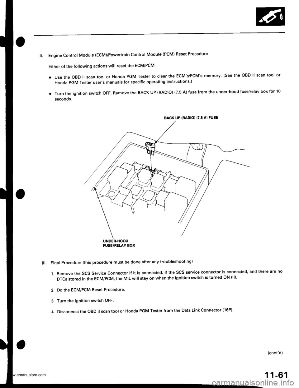
ll. Engine Controt Module (EcM)/Powertrain Control Module {PCM) Reset Procedure
Either of the following actions will reset the ECM/PCM.
. use the oBD ll scan tool or Honda PGM Tester to clear the ECM'�s/PCM'�s memory. (see the oBD ll scan tool or
Honda PGM Tester user's manuals for specific operating instructions )
. Turn the ignition switch oFF. Remove the BACK UP (RADIO) (7.5 A) fuse from the under-hood fuse/relay box for 10
seconos.
lll. Final Procedure {this procedure must be done after any troubleshooting)
1. Remove the SCS Service Connector if it is connected. lf the SCS service connector is connected. and there are no
DTCS stored in the ECM/PCM, the MIL will stay on when the ignition switch is turnsd oN (ll).
2. Do the ECM/PCM Reset Procedure.
3. Turn the ignition switch OFF
4. Disconnect the OBD ll scan tool orHonda PGM Tester from the Data Link Connector ( 16P)'
(cont'd)
1 1-61
BACK UP {RADIOI I7,5 AI FUSE
FUSE/RELAY BOX
www.emanualpro.com
Page 269 of 1395

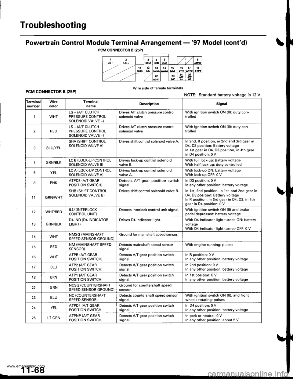
Powertrain Control Module Terminal Arrangement -'97 Model
FCM CONNECTOR A (32P)NOTE: Standard battery voltage is 12 V.
Wire side of lemale terminals
f€rminalnumlreJWirecolor
Telminalnama
DescriptionSignal
YELlNJ4 (No.4 FUELINJECTOR)Drives No. 4 {uel injector.With engine running: duty controlled
2BLUlNJ3 (No.3 FUELINJECTOR)Drives No. 3luel injector.
REDlNJ2 {No.2 FUELINJECTOR)Drives No.2 tuel injector.
BRNlNJl (No. l FUELINJECTOR)Drives No. 1 fuel injector.
5BLK WHTSO2SHIC (SECONDARY
HEATED OXYGEN SENSOR HEATER CONTROL)
D ves secondary heated oxygensensor heater.With ignition switch ON {ll): battery voltageWith fully warmed up engino running: dutycontrolled
6BLKAr'YHT
PO2SHTC (PRIMARY
HEATED OXYGENSENSOR HEATERCONTROL}
Drives primary heated oxygensensor heater,With ignition switch ON lll): battery voltagewith fully warmed up engine running: dutycontroll6d
I8RN/BLKLGl (LOGIC GROUND}Ground forthe PCM control circuit.Less than 1.0 V at all times
10BLKPG1 lPOWER GROUND}Ground for the PCM power circuit.
l1YEUELKIGPl lPOWER SOURCE}Power source for the PCM controlcircuit.
With ignition switch ON (ll): battery voltageWith ignition switch OFF: 0 V
12BLI(BLUIACV {IDLE AIRCONTROL VALVE}Drives IACV.With €ngine running: duty controlled
REDryEL
PCS (EVAP PURGECONTFOL SOLENOIDVALVE)
Drives EVAP purge controlsolenoid valve.
With engine running, engine coolantbelow 154'F (68"C): battery voltageWith engine running, engine coolantabove 154"F (68"C): duty controlled
16GRN/VELFLR (FUEL PUMP RELAY)Drives Iuel pump relay.0 V for two seconds after turning ignition
switch ON lll), then battery voltage
118LI(REDACC (A,/C CLUTCHRELAY}Drives Ay'C clutch relay.With comoressor ON: 0 VWith compressor OFF: baftery voltage
18GRN/ORNMIL (MALFUNCTION
INDICATOR LAMP}Drives MlL.With MIL turned ON: 0 VWith MIL turned OFF: baftery voltage
19*WHT/GRNALTC (ALTERNATOR
CONTROL}Sends alternator control signal.With tully warmed-up engine running:
battery voltageDuring driving with smallelectrical load:0 '
20YEUGRNICM (IGNITION CONTROLMODULE)Sends ignition pulse.With ignition switch ON (ll): baftery voltageWith engine running: pulses
22BRN/BLKLG2 (LOGIC GROUND}Ground tor the PCM control circuit.Less than 1.0 V at alltimes
23BLKPG2 {POWER GROUND}Ground lor the PCM power circuit.
24YEUBLKIGP2 {POWER SOURCE}Power source for the PCM controlcircuit.
With ignition switch ON (ll): battery voltage
With engine switch OFF: 0 V
27GRNFANC (RADIATOR FANCONTROL)Drives radiator {an relay.With radiator fan running: 0 VWith radiator fan stopped: baftery voltage
*: USA
{cont'd)
11-67
www.emanualpro.com
Page 270 of 1395
Troubleshooting
PCM CONNECTOR B I25PI
Powertrain Control Module Terminal Arrangement -'97 Model (cont'dl
Wire side of female terminalsPCM CONNECTOR B I25P}NOTE: Standard battery voltage is l2 V.
1 1-68L
TerminelnumbercolorTerminalnameOescriptionSignal
1LS 1A/T CLUTCHPRESSURE CONTROLSOLENOID VALVE -)
Drives A,/T clutch pressure controlsolenoid valveWith ignition switch ON (ll): duty con-trolled
2REDLS + (A"/T CLUTCHPRESSURE CONTROLSOLENOID VALVE +)
Drives A,/T clutch pressure controlsolenoid valveWith ignition switch ON (ll)r duty controlled
38LU//EL
SHA (SHIFT CONTROLSOLENOID VALVE A)Drives shift control solenoid valve A.In 2nd, R position. in 2nd and 3rd gear inD4, D3 position: Battery voltageIn lst gear in D4, D3 position, in 4th gear
in D4 position: 0 V
4GRN/BLKLC B (LOCK-UP CONTFOLSOLENOID VALVE B)Drives lock-up control solenoidvalve B,With full lock-up; Baftery voltageWith half lock-up: duty controlled
5YELLC A (LOCK.UP CONTROLSOLENOID VALVE A)Drives lock-up control solenoidWith lock'up ON: battery voltageWith lock-up OFF:0 V
IPNKATPD3 (Ay'T GEARPOSITION SWITCH}Detects A/T gear position switchsignal. _
In D3 position:0 Vln any other position: battery voltage
11GRN/VVHT
SHB (SHIFT CONTROLSOLENOID VALVE 8}Drives shift control solenoid valve B.In 1st, 2nd position, in 1st and 2nd gear inD4, D3 position: Battery voltageIn R position, ;n 3rd gear in 04, D3, in 4thgear in D4 position: 0 V
12WHT/BEDILU (INTERLOCK
CONTROL UNITiDetects interlock control unh signal.With ignition switch ON (ll)and brakepedal depressed: battery voltage
GRN/BLKD4IND (04 INDICATORLIGHT}Drives Dl indicator light.With D4 indicator light turned ON: batteryvoltageWith D4 indicator light turned OFF: 0 V
14NMSG (MAINSHAFT
SPEED SENSOR GROUND}Ground tor mainshaft speed sensor.
REDNM (MAINSHAFT SPEEDSENSOR)Detects mainshaft speed sensorsrgnal,With engine running: pulses
16ATPR (A"/T GEARPOSITION SWITCH)Detects A/T gear position switchsrgnal.InRposition:0VIn any other position: battery voltage
1'lBLUATP2 (A./T GEARPOSITION SWITCH)Detects A/T gear position switchsrg nal,In 2nd position: 0 VIn any other position: battery voltage
18BRNATP1 (4,,/T GEARPOSTTTON SWTTCH)Detects A/T gear position switchsrg nal,ln lst position: 0 VIn any other position: battery voltage
22GBNNCSG (COUNTERSHAFT
SPEED SENSOR GROUND)Ground tor countershaft speedsensor,
23BLUNC (COUNTERSHAFT
SPEED SENSOR)Detects countershaft speed sensorsrgnal.With agnition switch ON (ll), and lrontwheels rotating: pulses
24YELATPD4 (M GEARPOSITION SWITCH)Detects A,/T gear position switchsrgnal.In D4 positionr 0 VIn any other position: battery voltage
25LT GRNATPNP {A/T GEARPOSITION SWITCH)Detects A/T gear position switchsignal.In park or neutral:0 VIn any other position: about 5 V
www.emanualpro.com
Page 271 of 1395
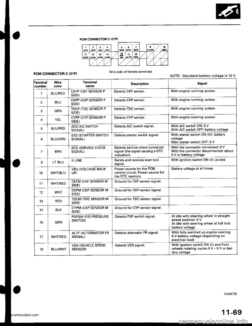
PCM CONNECTOR C (31PI
ferminalnumberWirecolorTerminalnameDoscriptionSignal
'tBLUiREDCKFP (CKF SENSOR PSIDE)Detects CKF sensor.With engine running: pulses
2BLUCKPP (CKP SENSOR PSIDE)Detects CKP sensor.With engine running: pulses
3GRNTDCP (TDC SENSOR PSIDE)Detects TDC sensor.With engine running: pulses
4YELCYPP (CYP SENSOR PSIDE)Detects cYP sensor.With engine running: pulses
5BLU,frEDACS (A/C SWTTCHSIGNAL)Detects A,/C switch signal.With AJC switch ON: 0 VWith A,/C switch OFF: battery voltage
BLU/ORNSTS (STARTER SWITCHSIGNAL)
Detects starter switch signal.With starter switch ON (lll): bafteryvoltageWith staner switch OFF: 0 V
7BRNSCS (SERVICE CHECKSIGNAL)
Detects service check connectorsignal (the signal causing a DTCindication)
With the connector connected: 0 V
With the connector disconnected: about
5 V or battery voltage
8LT BLUK-LINESends and receives scan toolsrgnal.With ignition switch ON (ll): pulses
10WHT/BLUVBUUP)
(VOLTAGE BACKPower source tor the PCMcontrol circuit. Power source for
the DTC memory
Battery voltage at all times
11WHT/REDCKFM (CKF SENSOR MSIDE)Ground for CKF sensor signal.
12WHTCKPM (CKP SENSOR I\4SIDE)Ground lor CKP sensor signal.
13REDTDCM (TDC SENSOR MSIDE}Ground for TDC sensor signal.
14BLKCYPM (CKP SENSOR MSIDE}Ground for CYP sensor signal.
16GRN
PSPSW (P/S PRESSUREswtTcH)Detects PSP switch signal.At idle with steering wheel in straightahead position:0 VAt idle with steering wheel at full lock:
battery voltage
17WHT/REDALTF (ALTERNATOR FRSIGNAL)
Detects alternator FR signal.With fully warmed up engine running:
0 V-battery voltage {depending onelectrical load)
18BLUA/VHTVSS (VEHICLE SPEEDSENSOR)Detects VSS signal.Wirh ignition switch ON (ll) and frontwheels rotating: cycles 0 V - 5 V or bat-tery voltage
Wire side of femaie terminalsPCM CONNECTOR C {31PINOTE: Standard battery voltage is 12 V.
(cont'd)
www.emanualpro.com
Page 272 of 1395
Troubleshooting
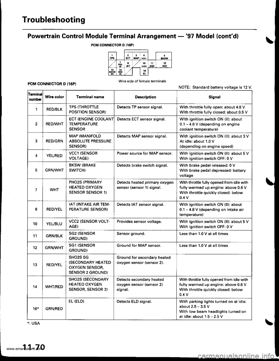
Powertrain Gontrol Module Terminal Arrangement -'97 Model (cont'd)
PCM CONNECTOR O {16PI
PCM CONNECTOR D (I6P)Wire side of f6male terminals
NOTE: Standard battery voltage is 12 V.
f.rminal
numbcrWir! colorT€rminal nam6DescriptionSignal
1RED/BLKTPS ffHROTTLE
POSITION SENSOR}
Detects TP sensor signal.With throttle fullv oDen: about 4.8 V
With throttle fullv closed: about 0.5 V
RE D,4/VHT
ECT (ENGINE COOLANT
TEMPERATURE
SENSOR
Detects ECT sensor signal.With ignition switch ON {ll): about
0.1 - 4.8 V (depending on engine
coolant temperature)
RED/GRN
MAP (MANIFOLD
ABSOLUTE PRESSURE
SENSOR)
Detects MAP sensor signal.With ignition switch ON (ll): about 3 V
At idle; about 1.0 V(depending on engine speed)
YEUREDVCCl (SENSOR
VOLTAGE)
Pow€r source for MAP sensor.With ignition switch ON (ll): about 5 V
With ignition switch OFF: 0 V
EG R N/WHT
BKSW (BRAKE
SWITCH)
Detects brake switch signal.With brake pedal released:0 V
With brake pedal depressed: battery
voltage
7WHT
PHO2S (PRIMARY
HEATED OXYGEN
SENSOR SENSOR 1)
Detects heated primary oxygen
sensor (sensor 1) signal.
With throttle fully opened from idle with
fully warmed up engine: above 0.6 V
With throttle quickly closed: below
0.4 v
8RED//E L
IAT (INTAKE AIR TEM.
PERATURE SENSOR)
Detects IAT sensor signal.With ignition switch ON lll): about
0.1 - 4.8 V (depending on intake air
temperaturel
10YEUBLUVCC2 (SENSOR VOLT-
AGEI
Provides sensor voltage.With ignition switch ON (ll): about 5 V
With ignition switch OFF: 0 V
11GRN/BLKSG2 (SENSOR
GROUND)
Sensor ground.Less than 1.0 V at all times
12GRN/WHTSGl (SENSOR
GROUND)
Ground for MAP sensor.Less than 1.0 V at all times
13RED/YE L
SHO2S SG(SECONDARY HEATED
OXYGEN SENSOR,
SENSOR 2 GROUND)
Ground for secondary heated
orygen sensor (sensor 2).
14WHT/RED
SHO2S (SECONDARY
HEATED OXYGEN
SENSOR, SENSOR 2)
Detects secondary heated
orygen sensor (sensor 2)
signal,
With throttle fully opened from idle with
fully warmed up engine; above 0.6 V
With throttle quickly closed: below
0.4 v
16*GRN/RED
EL (ELD)Detects ELD signal.With parking lights turned on at idle
about 2.5 - 3.5 V
With low beam headlights turned on
at idle: about 1.5 - 2.5V
1-70
www.emanualpro.com
Page 273 of 1395

Engine/Powertrain Control Module Terminal Arrangement - 38 - 00 Models
ECM/PCM CONNECTOR A (32P}
,/./5aIsca
,/ l,/t5ItsTs
n2ls!uCI
Wire side ot female terminalsECM/FCM CONNECTOR A {32P)NOTE: Standard baftery voltage is '12 V.
D93criptionSignal
3BLU2WBS {EVAP BYPASSSOLENOID VALVE)Drives EVAP bvoass solonoid valve.With ignirion switch ON {ll)r battery voltage
LT GRNMHTVSV {EVAP CONTROL CANISTEB VENT SHUT VALVE)D.ives EVAP controlcanisler vent shutWith ig^ition switch ON (ll): battery voltage
5',BLUCRS (CRUISE CONTROL SIG'NAL)Shift Oown signalinputfrcm cruise conWhen cruise control is used: pulses
6RED/YEL
PCS (EVAP PURGE CONTROLSOLENOID VALVE)Drives EVAP purge controlsolonoid valve.With engins running, engine coolant, below 154'F(68'C)r battery voltageWith engine running, engine coolant, above 154"F{6a'C}r duty conl.olled
8ELIOWHTSO2SHTC (SECONDARVHEATED OXYGEN SENSORHEATER CONTROL)
Drives sacondary heated oxygen sensorWith ignition switch ON (ll): banery voltageWith fully warmed up engine running: duty
10BRNSCS (SERVICE CHECX SIGNAL)Detects seNics check conneclor signal(he signalcausing a DTC indicatjon)with rhe lerminal connected:0 vWith the rerminaldisconnectedrabout 5 v or
l4'rGRN/8LKD4IND (D4INDICATOR)+3DIND (D INDICATORTIDrives D4*3. Dr'indicaior light.W,rh 04' , O" indrcator light turned O batter,
With D4*3, D*. indicator light turned OFFr0 V
16GRNI/ELFLR (FUEL PUMP RELAY)Drivss fusl pump relay.0 V for iwo seconds after ru'nin9 ign'lion swilchON lll), then banery voltage
17AL|(/REDACC (I/C CLUTCH RELAY}Drives l,/C clurch rclay.With compressor ONr0 VWith compressor OFF: battery voltage
18GRN/ORNMIL (MALFUNCTION INDICA.TOR LIGHT)Driv€s MlL.With MlLturned ON:0 VWith MIL turned OFF: battery voltage
19BLUNEP (ENGINE SPEED PULSE)Outputs engine spsed pulse.With sngine runnin9: pulses
20GRNFANC {RADIATOR FAN CONTROL)Drives r6diator fan rslay.With radaator fan running:0 VWith radaatorfan stopped: battery vollage
218LU/t/ELK-LINESends and receiv€s scan toolsignal.With ignition switch ON (ll): p'rlses
23WHT/REDSHO2S (SECONDARY HEATEDOXYGEN SENSOR. SENSOR 2iDetects secondary h€at€d oxygen sensorWith throttle fully opened from idle wilh fullywalmed up engine: above 0.6 Vwith rhrottle quickly closed: below 0-4 V
21BLU/WHTSTS (STARTER SWITCH SIG,NAL}Dotocts srarter switch signal.Whh staner switch ON (lll): batlery voltageWith srarter switch OFF: 0 V
26GBNPSPSW {P/S PsESSUFESWITCH SIGNAL)Detecrs PSP switch signal.At idle with steeing wh€el in stBighl ahead position: 0 VAt idls with nee ng wheel al full lockr banory voltage
2fBLU/BEOACS (Ir'C SWTCH SIGNAL}D€tects ly'C switch signal.With Ay'C switch ON:0 VWith l/C swil€h OFF: about 5 V
2A'\WHT/NEDSLU {INTERLOCK CONTROLUNIT)Orives interlock control unil.With ignilion switch ON (ll)and brake pedaldepressed: battery vohage
29LT GRNPTANK (FUEL TANK PRES'SURE SENSOR)Detocts fueltank pressure sensor signal.With agnition switch ON (ll) and fuel fill capopensd; about 2.5 v
GBN/FEDEL (ELD}Detects ELD signal.Wirh paaing rightstumed on at idle:about 2.5 - 3.5 VWith low beam headlights tumed on at idle:about 1.5-2.5V
GRN/WHTBKSW (BRAKE SWTTCH)Dst€cts brake switch signal.Wirh brake pedal released:0 VWith brake pedal depressed: battery vollage
13: '98 modsl
15: USA(cont'd)
11-71
www.emanualpro.com
Page 274 of 1395
Troubleshooting
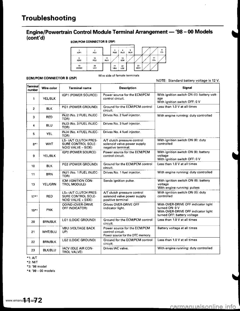
Engine/Powertrain Control Module Terminal Arrangement - '98 - 00 Models
(cont'd)
ECM/PCM CONNECTOR B {25PI
Wire side of female terminalsECM/PCM CONNECTOR B I25PI
*2t MlT*3: '98 model"4: '99 - 00 models
NOTE: Standard baftery voltage is l2
Ierminalnumb€tWire colorTerminsl nameDescriptionSignal
1YEUBLKIGPl (POWER SOURCE)Power source for the ECM/PClvlcontrol circuit.withagewith
ignition switch ON (ll): battery volt-
ignition switch OFF:0 V
BLKPG1 (POWER GROUND}Ground for the ECM/PClvl controlcircuit.Less than 1.0 V at all times
REDlNJ2 (No. 2 FUEL INJEC-roR)Drives No. 2 Iuel injector.With engine running: duty controlled
BLUlNJ3 1No. 3 FUEL INJEC-TOR)Drives No. 3Iuel jnjector.
YELlNJ4 {No.4 FUEL INJEC-TOR)Drives No. 4 fuel injector.
8*1WHTLS- (A"/T CLUTCH PRES.SURE CONTROL SOLE,NOID VALVE _ SIDE)
A,/T clutch pressure controlsolenoid valve power supplynegative terminal.
With ignition switch ON (ll): dutycontrolled
9YEUBLKIGP2 IPOWER SOURCE)Power source for the ECN,I/PCMcontrol circuit.With ignition switch ON (lll: bafteryvoltageWith ignition switch OFF:0 V
10BLKPG2 (POWER GROUND}Ground for the ECM/PCM controlcrrcurt.Less than '1.0 V at all times
' BRNlNJl (No. 1 FUEL INJECTOR)Drives No. l tuel injector.With engine running: duty controlled
YEUGRNrcM {rGNrTroN coN-TROL MODULE)Sends ignition pulse.With ignition switch ON (ll): batteryvoltageWith engine running: pulses
17*1REDLS+ (A,,IT CLUTCH PRESSURE CONTROL SOLE-NOID VALVE + SIDE)
A,/T clutch pressure controlsolenoid valve power supplypositive terminal
With ignition switch ON (ll): dutycontrolled
19*.PNK
ODIND (OVER-DRIVE
OFF INDICATOR}Drives OVER-DRIVE OFFindicator light.With OVER-DRIVE OFF indicator lightturned ON: 0 VWith OVER-DRIVE OFF indicator lightturned OFF: battery voltage
20BRN/BLKLG1 (LOGIC GROUND)Ground for the ECM/PCM controlcircuit.Less than 1.0 V at all times
WHT/BLUVBU (VOLTAGE BACKUP)Power source for the ECM/PCMcontrol circuit.Power source forthe DTC memory.
Battery voltage at all times
22BRN/BLKLG2 (LOGIC GROUND)Ground for the ECN4/PCM controlctrcutt,Less than 1.0 V at all times
23BLVBLUIACV {IDLE AIR CON.TROL VALVE)Drives IAC valve.With engine running: duty controlled
11-72
www.emanualpro.com
Page 275 of 1395
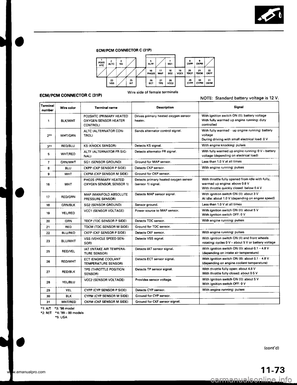
ECM/PCM CONNECTOF C (31PI
Wire side o{ female terminal€ECM/PCM CONNECTOR C (31P)NOTE: Standard battery voltage is 12 V.
TermidalD.3criptionSignal
8LI(WHTPOzSHTC {PRIII4ABY HEATEDOXYGEN SENSOR HEATERCONTROL)
Drivss prim6ry h$ted oxygsn sensorWilh ignition switch ON (ll): baneryvoltsgeWith ftrllywarmsd up €ngine runnang: duty
2"WHT/GBNALTC (ALTERNATOR CON,TROL)Sonds alternalor control signsl.With fully wafmod up €ngine rnningr ban€ryvoltagoDu ng driving with small elsctrical lo6d: 0 v
3'1FED/8LUKS (KNOCK SENSOR)Dstects KS signal.With engine knockang: pulses
5WHT/REDALTF (ALTERNATOR FR SIG-NAL}Detects alternator FR signal.Wth fullywarmed up €ngine running:0 V-batteryvoltag€ {d€pending on slsctrical load)
1GRN,4trHTSG1 (SENSOR 680UND}Ground for l/tAP sensor.L€ss than 1.0 v 6t all times
8BLUCKPP (CKP SENSOF P SIDE)Dat€cls CKP s6nsor.With €ngin€ runningr puls€s
9CKPI.,I| {CKP SENSOF M SIDE)Ground for CKP s€nsor.
15PHO2S {PRIMARY HEATEDOXYGEN SENSOR, SENSOR 1)Detocts pfimary he6t6d oxygen ssnsor
{sonsor 1)signal.with ihfottls fully opened from idle with fully,
walm6d up engins: above 0.6 VWith throttlo quickly clossd: below 0.4 v
17RED/GRNMAP (MANIFOLD ABSOLUTEPRESSURE SENSOR)
D6tects MAP s€nsor sign6l.With ignition switch ON (ll):about 3 VAt idls: aboul 1.0 V {dspsnding on engine speed)
18GRN/BLKSG2 (SENSOB GNOUNDiLsss than 1.0 V at all tim€s
19YEUBEDVCCl {SENSOR VOLTAGE)Power soufce to MAP s€nsor.With ignition switch ON (ll): about 5 VWith ignition switch OFF:0 V
20GRNTDCP {TDC SENSOR P SIDE)Derecis TDC sensor.With engine funning: Pulses
2lREDTDCM ITDC SENSOR M SID€)Ground for TDC sensor.
22BLU/REDCKFP (CKF SENSOR PSIDE)Dstscts CKF s€nsor.With sngins running: pulsss
23BLU/WHTVSS (VEHICLE SPEED SEN-soR)Dstscrs vss signal.With ignition switch ON (ll)and front wheelsrotaringrcyclss 0 v- 6bout 5 V or ban€ry voltage
25RED//ELIAT (INTAKE AIR TEMPERA'TURE SENSOB)Detacts IAT sensor signal.With igniiion switch ON (ll): about 0.1 - 4.8 V(d€p€nding on iniate air t€mp€raturc)
26REO/WHTECT {ENCINE COOLANTTEMPERATURE SENSOR)oetscts ECT sensor signal.With ignition switch ON (ll): about 0.1 4.8 V
{doponding on 6ngin€ coolanl lemper6tu16)
27RED/BLKTPS (THROTTLE POSITIONSENSOR)Dotects TP sensor signrl.with rhrottls fully op€n: aboui 4.8 vwith throtrl6 fullyclosed: about 0.5 v
2AYEUBLUVCC2lSENSOR VOLTAG€}Provid€s s€nsor voltage.With ignilion switch ON (ll): about 5 VWhh ignition switch OFF: 0 V
29YELCYPP ICYP SENSO8 P SIDE)Dsrscts CYP sensor.With €ngins runningr pulsss
30BLKCYPM (CYP SENSOR M SIDE)Ground for CYP sansor.
31WHT/REDCKFM {CKF SENSOR M SIDE)6.ound lof CKF ssnsor signal.
11. AfT 13. '94 model'2:M/T 14:'99- 0o modsls.5: USA
(cont'd)
11-73
www.emanualpro.com
Page 276 of 1395
Troubleshooting
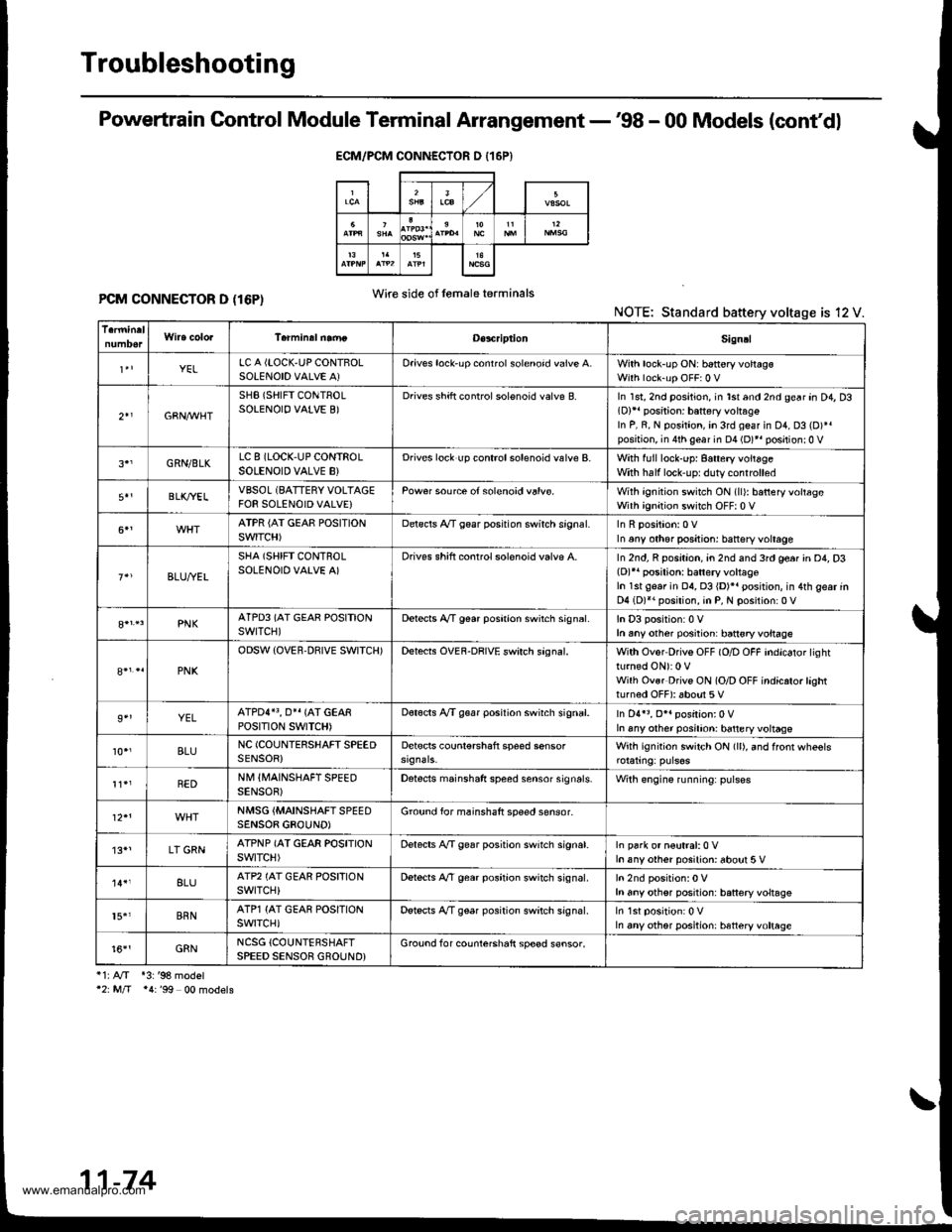
Powertrain Control Module Terminal Arrangement -'98 - 00 Models (cont'dl
PCM CONNECTOR D (16P)NOTE: Standard battery voltage is 12 V.
i1:A/T *3:'98 model'2: M/T *4:'99 00 models
ECM/PCM CONNECTOR D {16P}
Wire side of lemaleterminals
D€s4riptionSign!l
YELLC A {LOCK,UP CONTBOLSOLENOID VALVE A)Oriv€s lock'up conrrol solenoid valve A.With lock-up ON: b6ttery voltagsWith lock-up OFF:0 V
2+1GBN,M/HT
SHB (SHIFT CONTROLSOLENOIO VALVE B)Drives shift controlsolenoid valve B.In 1st, 2nd position, in lst and 2nd gear an D4, D3(D)11 position: battery vohag€In P, R, N position, in 3rd geaf in D1, D3 (D)*.position, in 4th gear in D4 (D)*r positionr0 V
GRN/BLKLC 8 (LOCK,UP CONTROLSOLENOID VALVE B}Drives lock up controlsolenoid valve B.With full lock-up: 8attery voitageWith half lock'uprduty controlled
BLK/YELVBSOL (BATTERY VOLTAGEFOR SOLENOID VALVE}Pow€r source of solenoid valvs.With ignition switch ON (ll): batteryvoltageWith ignition switch OFF| 0 V
ATPR {AI GEAE POSITIONSWITCH)Delscls A/T gear posrtion swirch srgnal.In any other positjon: battsry voltage
BLU,ryEL
SHA (SHIFT CONTROLSOLENOID VALVE A)Drives shift conrrol solenoid valvp A.In 2nd, R position, an 2nd and 3rd ge6r in D4, D3(D)r' posilion: batlery voltageIn 1st gear in 04, 03 {D)}. position, in 4th gear inD4 (D)*. position, in P, N position:0 V
PNKATPD3 (AT GEAR POSITIONswrTcH)Detects A,/T g€ar poshion swirch sign6l.In D3 position:0 Vh any other posiiion: ban€ryvoltage
PNK
ODSW (OVER.DBIVE SWITCH)Detects OVEF-DRIVE swirch sagnal.With Ovor Drivs OFF (O/D OFF indicator lightturned ON): 0 VWilh Ovsr Drivs ON (O/D OFF indicrto.lashtturned OFF): about 5 V
9''YELATPDI}3, O}I {AT GEARPOStTtON SWTTCH)Dot€cts A/T g€ar position swirch signal.In D4r3, O*. position:0 VIn any other posilion: battery voltage
10.,BLUNC (COUNIERSHAFT SPEEDSENSOR)Detscts counl€rshaft speed sensorWith ignition switch ON (ll), and ffonr wheels
REDNM IIVAINSHAFT SPEEDSENSOB)Detects mainshaft speed sensor sign6ls.Wilh engine running: pulses
NMSG {MAINSHAFTSPEEDSENSOB GBOUND)Ground for mainshaft speed sensor-
'13*1LT GRNATPNP (AT GEAR POSITIONswtTcH)Delects A,/T gear position switch signat.In park or n€utral:0 Vh any other posilion: about 5 V
8LUATP2 (AT GEAR POSFIONswrTcH)Dstects A,/T gear position switch signal.h any othsr position: battery voltsgs
15.'BRNATP1 {AT GEAR POSITIONswrTcH)Detscts A/T gear position switch signal.In any other position: htteryvoltage
t6''GRNNCSG {COUNTERSHAFTSPEED SENSOR GROUND}Grouod for counterchaft sp€ed s€nsor.
11-74
www.emanualpro.com
Page 282 of 1395

PGM-FI System
System Description
INPUTS
CKP/TDC/CYP Sensor
CKF Sensor
MAP Sensor
ECT Sensor
IAT Sensor
TP Sensor
Primary HO2S
Secondary H02S
vss
KS*5
BARO Sensor
ELD*6
Starter Signal
ALT FR Signal
Air Conditioning Signal
Ay'T Gear Position Signal*1
Baftery Voltage (lGN.1)
Brake Switch Signal
PSP Switch Signal
Fuel Tank Pressuae Sensor*4. *5
Countershaft Speed Sensor*1
Mainshaft Speed Sensor*r
OVER-DRIVE Switch Signal*s
ENGINE CONTROL MODULE (ECM)/
POWERTRAIN CONTROL MODULE (PCM) OUTPUTS
|iuel 1"j""- Th,rhg ""d Drrafr";-l
Et*-.nt"tdt"cont.orl
to,r*,c;;trffi;]
l.----.---:. .Lrgnrnon |lmrng Lonrror I
Ecir/PcM B*k',p Fr""il]
m;"t-ll-r*'io*l
Fuel Injectors
PGM-Fl Main Relay (Fuel Pump)
MIL
IAC Valve
Ay'C Compressor Clutch Relay
Radiator Fan Relay
Condenser Fan Relay
ALT
tcM
EVAP Purge Control Solenoid
Valve
Primary HO2S Heater
Secondary H02S HeaterEVAP Bypass Solenoid Valve*a *5
EVAP Control Canister Vent Shut
DLC
Lock-up Control Solenoid Valve*l
Shift Control Solenoid Valve*1
Ay'T Clutch Pressure Control
Solenoid Valve*1
D4 Indicator Light'1 *3, *a
D Indicator Light,l *5
OVER-DRIVE OFF Indicator
Lighl*t *:
*1: A/T {3:'97 model'2: M/f +4:'98 model*5: '99 - 00 models"6: USA
PGM-Fl System
The PGM-Fl system on this model is a sequential multiport fuel injection system.
Fuel iniecior Timing and Duration
The ECM/PCM contains memories for the basic discharge durations at various engine speeds and manifold pressure. The
basic discharge duration, after being read out from the memory, is further modified by signals sent from various sensors
to obtain the final discharge duration.
ldle Air Control
ldle Air Control Valve (lAC Valve)
When the engine is cold, the Ay'C compressor is on, the transmission is in gear, the brake pedal is depressed, the P/S load
is high, or the alternator is charging, the ECM/PCM controls current to the IAC Valve to maintain the correct idle speed.
lgnition Timing Control
o The ECM/PCM contains memories for basic ionition timing at various engine speeds and manifold air flow rates.
lgnition timing is also adjusted for engine coolant temperature.
. A knock control system was adopted which sets the ideal ig nition timing for the octane rating of the gasoline used.*s
Other Control Funstions
1. Starting Control
When the engine is started. the ECM/PCM provides a rich mixture by increasing fuel injector duration.
2. Fuel Pump Control
. When the ignition switch is initially turned on (ll). the ECMiPCM suppli€s ground to the PGM-FI main relay that
supplies current to the fuel pump for two seconds to pressurize the fuel system.
. When the engine is running, the ECM/PCM supplies ground to the PGM-FI main relay that supplies current to the
fuel oumo.
. When the engine is not running and the ignition is on, the ECM/PCM cuts ground to the PGM-FI main relay which
cuts current to the fuel pump.
1 1-80
www.emanualpro.com