Mounting assembly HONDA CR-V 1997 RD1-RD3 / 1.G User Guide
[x] Cancel search | Manufacturer: HONDA, Model Year: 1997, Model line: CR-V, Model: HONDA CR-V 1997 RD1-RD3 / 1.GPages: 1395, PDF Size: 35.62 MB
Page 705 of 1395
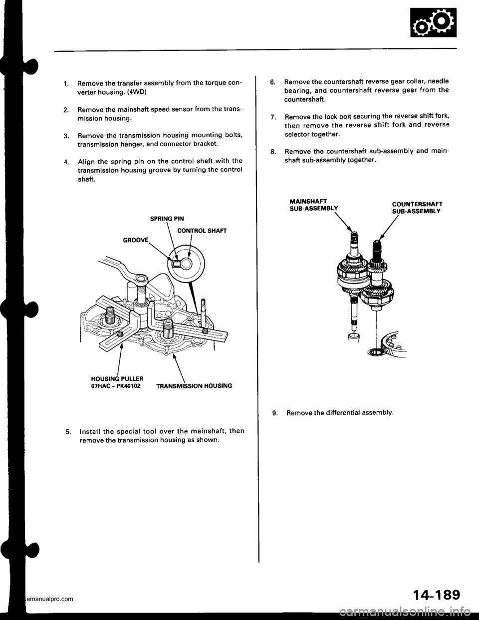
1.Remove the transfer assembly from the torque con-
verter housing. (4WD)
Remove the mainshaft speed sensor from the trans-
mission housing.
Remove the transmission housing mounting bolts,
transmission hanger, and connector bracket.
Align the spring pin on the control shaft with the
transmission housing groove by turning the control
shaft.
Install the special tool over the mainshaft. then
remove the transmission housing as shown.
4.
SPRING PIN
7.
Remove the countershaft reverse gear collar, needle
bearing, and countershaft revsrse gear from the
countershaft,
Remove the lock bolt securing tho reverse shift fork,
then remove the reverse shift fork and reverse
selector together.
Remove the countershaft sub-assemblv and main-
shaft sub-assembly together,
9. Remove the differential assembly.
8.
14-189
www.emanualpro.com
Page 742 of 1395
Differential
Side Clearance Inspection
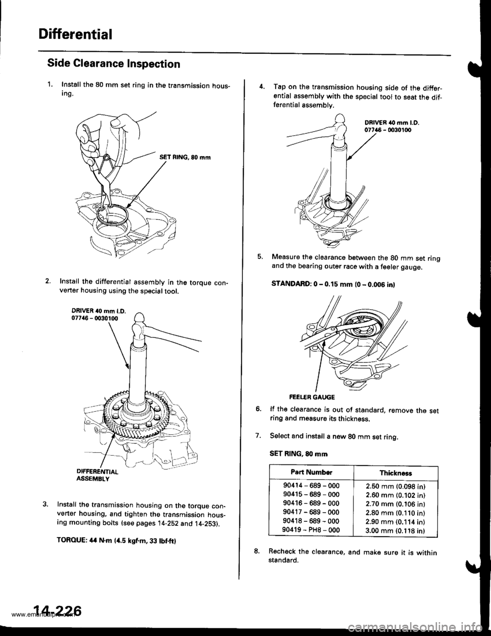
1. Instsll the 80 mm set ring in the transmission hous-Ing,
SET RING, 80 mrn
Install the differential assembly in the torque con-verter housing using the specialtool.
Install the transmission housing on the torque con-verter housing, and tighten the transmission hous-ing mounting bolts (see pages 14-252 and t4-253).
TOROUE: 4a N.m l/r.5 kgf.m, 33 tbt.ftl
14-226
4. Tap on the transmission housing side of the diffsrential assembly with the special tool to seat the dif-ferential assemblv.
DBIVER ilo m.n LO.0t746 - 0030100
Measure the clearancs between the 80 mm set ringand the bearing outer race with a feeler gauge,
STANDARD: 0 - 0.15 mm (0 - 0.006 inl
FEEI..ER GAUGE
lf the clearance is out of standard, remove rne setring and measurs its thickness.
Select and instsll a new 80 mm set ring.
SET RING, 80 mm
Recheck the clearance, and make sure it is withinstandard.
7.
Part NumborThicknoss
90414-689-000
90415-689-000
90416-689-000
90417-689-000
90418-689-000
90419-PH8-000
2.50 mm (0.098 in)
2.60 mm (0.102 in)
2.70 mm (0.106 inl
2.80 mm (0.110 in)
2.90 mm (0.114 in)
3.00 mm (0. t'18 inl
www.emanualpro.com
Page 766 of 1395
Transmission
Reassembly
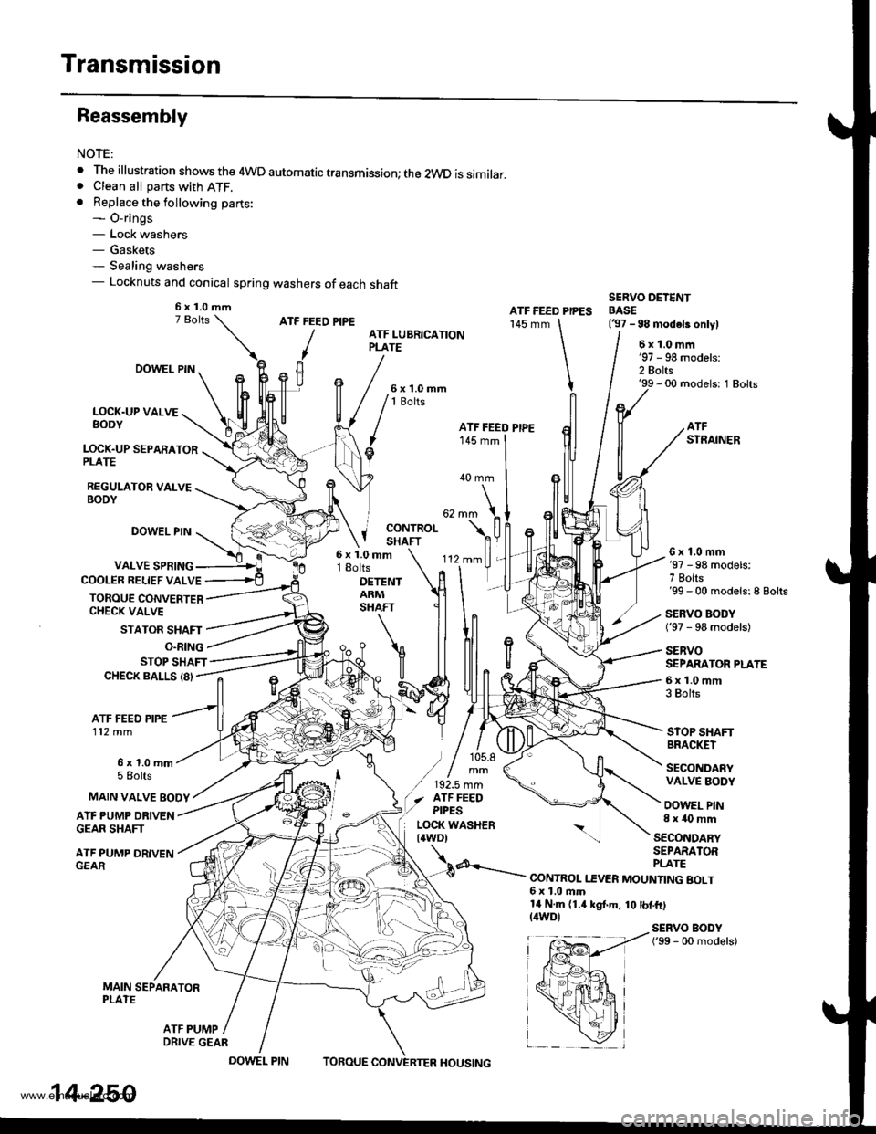
NOTE:
. The illustration shows the 4WD automatic transmission; the 2WD is similar.. Clean all parts with ATF.. Replace the following parts:- O-rings- Lock washers- Gaskets- Sealing washers- Locknuts and conical spring washers of each shaft
ATF FEED PIPE
/
ATF FEED PIPES145 mm
SERVO DETENTBASE(37 -98 modeb onlylATF LUBRICATIONPLATE6x1.0mm
2 Bolts'99 - 00 models: 1 Bolts
LOCK.UP VALVEBODY
LOCK.UP SEPARATORPLATE
REGULATOR VALVEBODY
DOWEL PIN
DOWEL PIN
VALVE SPRING
STATOR SHAFT
'-
'112mmll,
rlT
ATFSTRAINER
40 mm
j coNrRoLI SHAFT
COOLER BELIEF VALVE
TOROUE CONVERTERCHECK VALVE
6x1.0mm18olts
DETENTARMSHAFT
6x1,0mm'97 - 98 models:7 Bolts'99 - 00 models:8 Bolts
SERVO BODY('97 - 98 models)
SERVOSEPARATOR PLATE
6x1.0mm3 Bolts
STOP SHAFTBRACKET
SECONDARYVALVE BODY
OOWEL PIN8x40mm
O.RING
STOP SHAFTCHECK BALLS 18'
ATF FEED PIPE112 mm
6x1.0mm5 Eolts
ATF PUMP DRIVENGEAR SHAFT
ATF PUMP DRIVEN
MAIN SEPARATORPLATE
MAIN VALVE EOOY
SECONDARYSEPARATOR
d---.- PLATE--.- CONTROL I.EVER MOUNTING BOLT6x1.0ftm14 N.m (1.4 kgt.m, 10 tbf.ft)(4WD)SERVO BODY('99 - 00 models)
ATF PUMP
6x1.0mm
ATF FEEO PIPE
) / 105.8
/,,!.,::(./ afF FEEO,/ ptpEs
EP,---!ir{+*a r
fpffi4 i
x*hi
_ \zl
14-250
DRIVE GEAR
DOWEL PINTOBOUEHOUSING
www.emanualpro.com
Page 769 of 1395
17.
18.
19.
20.
21.
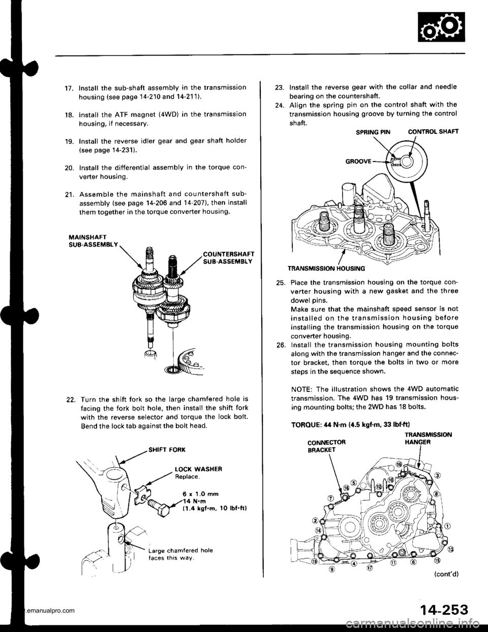
Install the sub-shaft assembly in the transmission
housing (see page 14-210 and 14-2'111.
lnstall the ATF magnet (4WD) in the transmission
housing, if necessary.
Install the reverse idler gear and gear shaft holder
(see page 14-231).
Install the differential assembly in the torque con-
verter housing.
Assemble the mainshaft and countershaft sub-
assembly (see page 14-206 and 14 207],, then install
them together in the torque converter houslng.
COUNTERSHAFTSUB-ASSEMBLY
Turn the shift fork so the large chamfered hole is
facing the fork bolt hole. then install the shift fork
with the reverse selector and torque the lock bolt.
Bend the lock tab against the bolt head.
SHIFI FORK
LOCK WASHERBeplace.
6 r 'l.O mm4 N.m(1.4 ksl.m. 1O lbt.ft)
Large chamfered hole
24.
Install the reverse gear with the collar and needle
bearing on the countershatt.
Align the spring pin on the control shaft with the
transmission housing groove by turning the control
shaft.
SPRING PIN CONTROL SHAFT
TRANSMISSION HOUSING
25. Place the transmission housing on the torque con-
verter housing with a new gasket and the three
dowel pins,
Make sure that the mainshaft speed sensor is not
installed on the transmission housing before
installing the transmission housing on the torque
converter housing.
26. Install the transmission housing mounting bolts
along with the transmission hanger and the connec-
tor bracket, then torque the bolts in two or more
steos in the seouence shown.
NOTE: The illustration shows the 4WD automatic
transmission. The 4WD has 19 transmission hous-
ing mounting bolts; the 2WD has 18 bolts.
TOROUE: 44 N.m {,[.5 kgf.m, 33 lbf'ft)
{cont'd)
14-253
SPRING PIN
TNANSMISSION
www.emanualpro.com
Page 775 of 1395
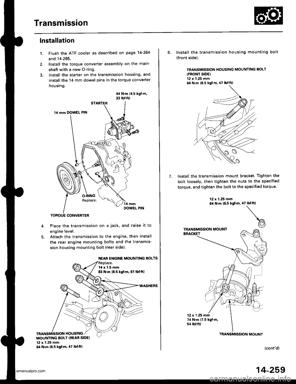
Transmission
1.
lnstallation
Flush the ATF cooler as described on page 14-264
and 14-265.
Install the torque converter assembly on the main-
shaft with a new O-ring.
lnstall the starter on the transmission housing, and
install the 14 mm dowel pins in the torque converter
housing.
44 N.m {{.5 kgf.m,33 rbf.f0
Place the transmission on a jack, and raise it to
engine level.
Anach the transmission to the engine, then install
the rear engine mounting bolts and the transmis-
sion housing mounting bolt (rear sidel.
14 mm DOWEL PIN
REAR ENGINE MOUNTING BOLTS
la x 1.5 mm8:l N.m (8.5 kgf.m, 61 lbf.ftl
MOUNTING BOLT {REAR SIDEI12 x 1.25 mm6il N.m 16.5 kgd.m, 47 tbt.ttl
6. Install the transmission housing mounting bolt
(front side).
TRANSMISSION HOUSING MOUNNNG BOLT
{FRONT SIDE)12 x 1.25 mm6,1 N m (6 5 kgl m, 47 lbf'ftl
Install the transmission mount bracket. Tighten the
bolt loosely, then tighten the nuts to the specified
torque, and tighten the bolt to the specified torque.
7.
12 x 1,25 mm6,a N.ft (6.5 kgtm,47rbf.ft)
t@
TRANSMISSION MOUNTBRACKET
12 x 1 .25 mm74 N.m (7.5 kgf.m,s{ tbtftl
(cont'd)
TBANSMISSION MOUNT
14-259
www.emanualpro.com
Page 803 of 1395
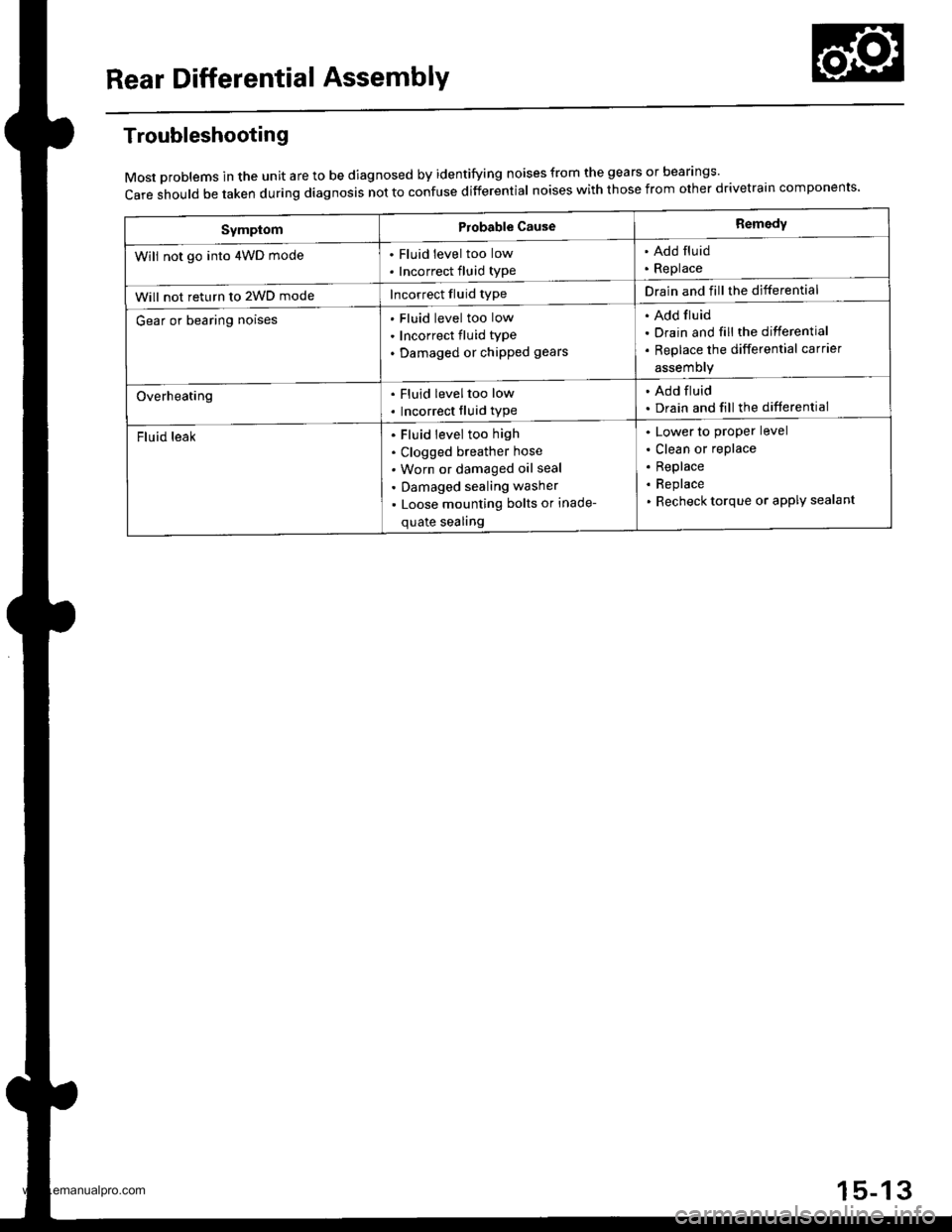
Rear Differential AssemblY
Troubleshooting
Most problems in the unit are to be diagnosed by identifying noises from the gears or bear'ngs'
care should be taken during diagnosis not to confuse differential noises with those from other drivetra'n components'
SymptomProbable CauseRemedy
Will not go into 4WD mode. Fluid level too low
. Incorrect fluid type
. Add fluid. Replace
Will not return to 2WD modeIncorrect fluid typeDrain and fill the differential
Gear or bearing noisesFluid level too low
Incorrect fluid type
Damaged or chipped gears
Add fluid
Drain and fill the differential
Replace the differential carrier
assemory
Overheating. Fluid leveltoo low
. Incorrect fluid type
. Add fluid. Drain and fill the differential
Fluid leakFluid level too high
Clogged breather hose
Worn or damaged oil seal
Damaged sealing washer
Loose mounting bolts or inade-
quate sealing
Lower to proper level
Clean or replace
Replace
Replace
Recheck torque or aPPIY sealant
15-13
www.emanualpro.com
Page 806 of 1395
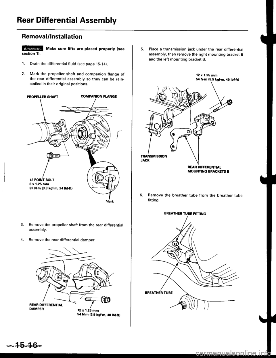
Rear Differential Assembly
Removal/lnstallation
l!!@ Make sure tifts are ptaced property lseesection 11.
1. Drain the differential flujd (see page 15-14).
2. Mark the propeller shaft and companion flange of
the rear differential assembly so they can be rein-
stalled in their original positions.
PROPELLER SHAFTCOMPA'{ION FLANGE
Remove the propeller shaft from the rear differential
assemory.
Remove the rear differential damper.
12 POtt'lT BOLI8 x 1.25 mm32 N.m 13.3 tgf.m. 2a lbtft,
Mark
12 x 1.25 mm
15-16
5,1 N.m 15,5 kgf.m, iO tbf.fO
5, Place a transmission jack under the rear differential
assembly, then remove the right mounting bracket B
and the left mounting bracket 8.
Remove the breather tube from the breather tubefitting.
BREATHER TUBE flTNNG
www.emanualpro.com
Page 807 of 1395
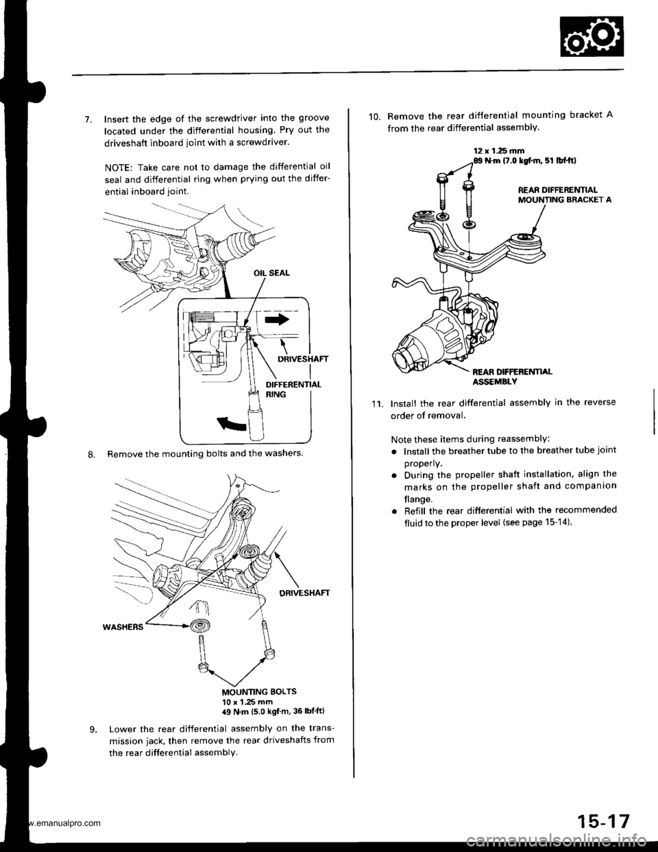
7. Insert the edge of the screwdriver into the groove
located under the differential housing Pry out the
driveshaft inboard ioint with a screwdraver.
NOTE: Take care not to damage the differential oil
seal and differential ring when prying out the differ-
ential inboard joint.
8. Remove the mounting bolts and the washers.
DRIVESHAFT
MOUNTING BOLTS'10 x 1 .25 mm,19 N'm (5 0 kgf m, 36 lbtftl
Lower the rear differential assembly on the trans-
mission jack, then remove the rear driveshafts from
the rea r difterential assembly.
DIFFERENTIAL
12 x 1.25 fifi
10. Remove the rear difterential mounting bracket A
from the rear differential assembly.
N.m {7.0 lgf.m. 5l lbl.tt)
REAR DIFFERENTIALMOUNTING BRACKET A
REAN DFFERENTI,ALASSEMBLY
11.Install the rear differential assembly in the reverse
order of removal.
Note these items during reassembly
. lnstall the breather tube to the breather tube joint
properly.
. During the propeller shaft installation, align the
marks on the propeller shaft and companion
flange.
. Reiill the rear differential with the recommended
fluid to the proper level {see page 15-14).
15-17
www.emanualpro.com
Page 813 of 1395
![HONDA CR-V 1997 RD1-RD3 / 1.G User Guide
Reassembly
1. Apply CVT fluid to the rubber of the oil strainer, then
install the oil strainer, the magnet, and the oil pump
pin to the differential carrier.
OIL PUMP PIN
DIFFERE]TTIAL CARRIERASSEMBL HONDA CR-V 1997 RD1-RD3 / 1.G User Guide
Reassembly
1. Apply CVT fluid to the rubber of the oil strainer, then
install the oil strainer, the magnet, and the oil pump
pin to the differential carrier.
OIL PUMP PIN
DIFFERE]TTIAL CARRIERASSEMBL](/img/13/5778/w960_5778-812.png)
Reassembly
1. Apply CVT fluid to the rubber of the oil strainer, then
install the oil strainer, the magnet, and the oil pump
pin to the differential carrier.
OIL PUMP PIN
DIFFERE]TTIAL CARRIERASSEMBLY
Align the oil pump pin with the groove of the rear oil
pump in the pump body assembly, then install the oil
pump body assembly to the differential carrier assem-
oty.
-n
CWfluid
2.
MAGNET
OIL PUMP BODY ASSEMBLY
3. Tighten the oil pump body assembly mounting
bolts.
4. Install the oil pump driveshaft by aligning the pro-
jection of the oil pump driveshaft with the groove of
the front oil pump in the oil pump body assembly.
lnstall in this direction.
Projection
6x1.0mm12 N.m 11.2 kg{.m,8.7 lbl.ft}
Install the thrust needle bearing.
Install the pressure plate assembly by aligning the
projection of the pressure plate with the groove of
the oil pump driveshaft.
5.
OIL PUMPDRIVESHAFT
(cont'd )
15-23
THRUST NEEDLE BEABING
PRESSURE PLATE
www.emanualpro.com
Page 845 of 1395
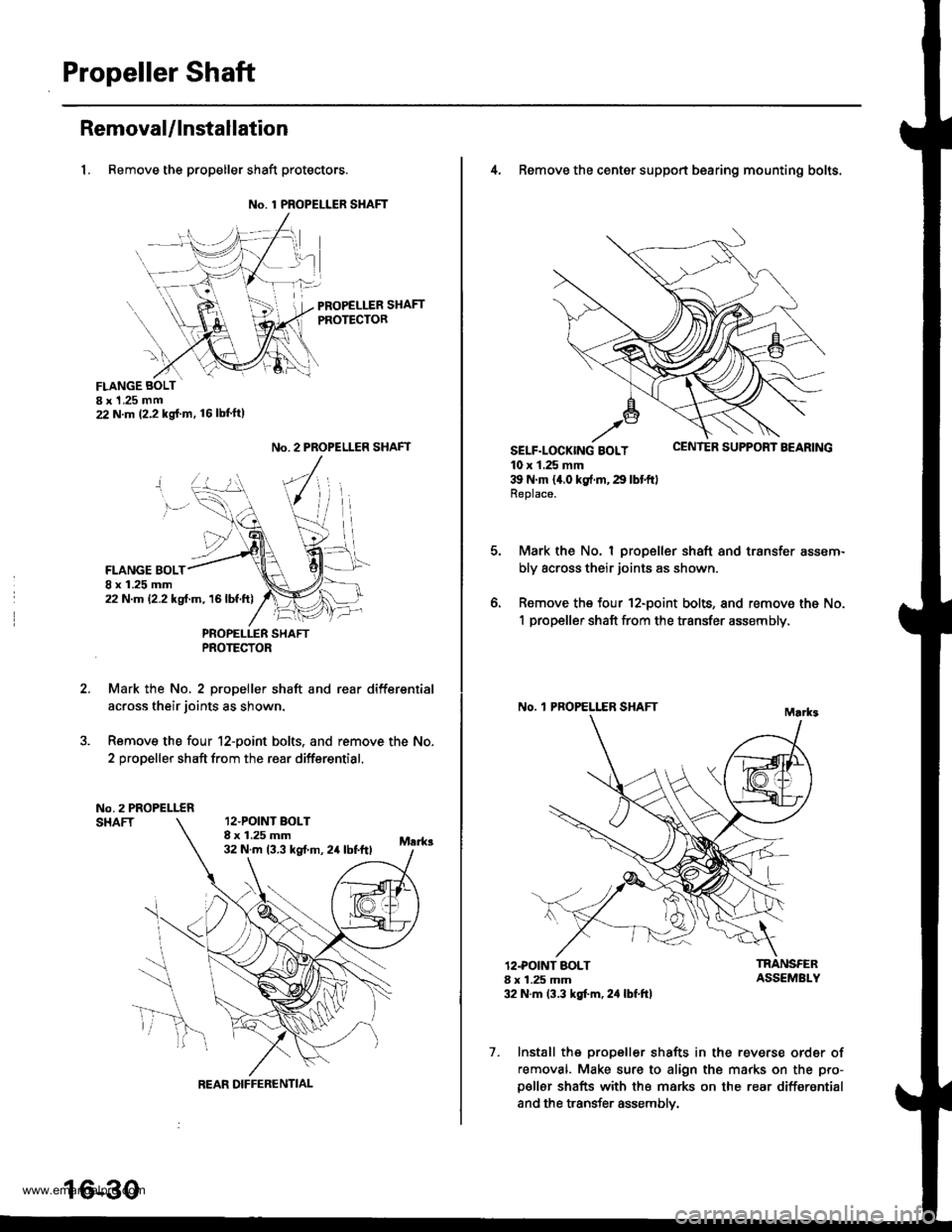
Propeller Shaft
RemovaUlnstallation
1, Remove the propeller shaft protectors.
No. 1 PROPELLER SHAFT
PROPELLER SHAFTPROTECTOR
FLANGE BOLTI x 1 .25 mm22 N.m (2.2 kg{.m. 16lbl'ft)
2.
No. 2 PROPELLER SHAFT
FLANGE BOLT8 x 1.25 mm22 N.m 12.2 kgf.m, 16lbf.ft)
PNOPELLER SHAFTPROTECTOR
Mark the No. 2 propeller shaft and rear differsntial
across their joints as shown.
Remove the four 12-point bolts. and remove the No.
2 propeller shaft from the rear differential.
No.2 PROPELLERSHAFT12.POINT BOLT8 x 1.25 mm32 N.m 13.3 kst m, 24 lbtftl
REAR DIFFERENTIAL
16-30
4, Remove the center support bearing mounting bolts.
SELF-LOCK|NG BOLT uErr rEn Durrr.r'r I I'EAnrNu
10 x 1.25 mm39 N'm 14.0 kg{.rn,29 lbtftlReplace.
Mark the No. I propeller shaft and transfer assem-
bly across their joints as shown.
Remove the four 12-point bolts, and remove the No.
1 propeller shaft from the transfer assembly,
No. 'l PROPELLER SHAFT
o.
12.POINT BOLT8 x 1.25 mm32 N.m 13.3 kgt'm, 2,1 lbf.ft)
TRANSFERASSEMBLY
7. Install the propeller shafts in the reverse order of
removal. Make sure to align the marks on the pro-
p€ller shafts with the marks on the rear differential
and the transfer assemblv.
www.emanualpro.com