HONDA CR-V 1997 RD1-RD3 / 1.G User Guide
CR-V 1997 RD1-RD3 / 1.G
HONDA
HONDA
https://www.carmanualsonline.info/img/13/5778/w960_5778-0.png
HONDA CR-V 1997 RD1-RD3 / 1.G User Guide
Page 789 of 1395

Replacement
SRS components are located in this area. Review the SRS
component locations, precautions, and procedures in the
SRS section {24} before performing repairs or service.
1. Remove the instrument panel lower cover and the
column covers (see section 17).
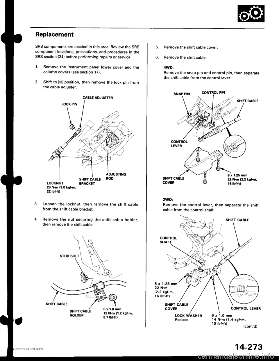
2. Shift to E position, then remove the lock pin from
the cable adiuster.
LOCK PIN
SHIFT CABLEBRACKET
ADJUSTINGROO
LOCKNUT29 N.m {3.0 kgl.m,2j2lbf.trl
Loosen the locknut, then remove the shift cablefrom the shift cable bracket.
Remove the nut securing the shift cable holder,
then remove the shift cable.
12 N.m {1.2 kgf.m,8.7 tbtfrl
CABLE ADJUSTER
STUO BOLT
6x1.0mm
Remove the shift cable cover.
Remove the shift cable.
4WD:
Remove the snap pin and control pin, then separatethe shift cable from the control lever.
CONTROL PIN
SHIFT CABLE
SHIFTCOVER
2WDi
Remove the control lever, then
cable from the control shaft.
separate the shift
t r 1.25 mm22 N.n 12.2 *glrn.16 tbf.trl
CONTROLSHAFT
8 x 1.25 mm22 N.m12.2 kgl-m,16 tbf.frl
SHIFT CABLECOVER
LOCK WASHER6x LOmm14 N.m {1.4 kgf.m,
(cont'd)
SHIFT CABI-E
10 tbt.lrl
14-273
www.emanualpro.com
Page 1028 of 1395

Dashboard
Genter Console Replacement
M/T model:
NOTE; Take care not to scratch the dashboard and related
parts,
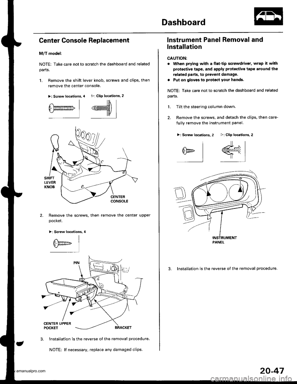
1, Remove the shift lever knob. screws and clips. then
remove the center console.
>: Screw location3,
I
6-Emmmn> |
4 >: Clip locations.2
#\*K/
I
Remove the screws, then
pocket.
remove the center upper
>: Screw locations, 4
3. Installation is the reverse of the removal procedure.
NOTE: lf necessary, replace any damaged clips.
lnstrument Panel Removal and
Installation
CAUTION:
. When prying with a flat-tip screwdriver. wrap it with
protestive tape, and apply prolestive tape around the
related parts, to provont damago,
a Put on glovss to protect your hands.
NOTE: Take care not to scratch the dashboard and related
pans.
1. Tilt the steering column down.
2. Remove the screws, and detach the clips, then care-
fullv remove the instrument oanel.
3. Installation is the reverse of the removal procedure.
>: Clip locations,2
r#sr |
=-l,]
>: Screw locations,2
^l
arl
l
PANEL
20-47
www.emanualpro.com
Page 1036 of 1395
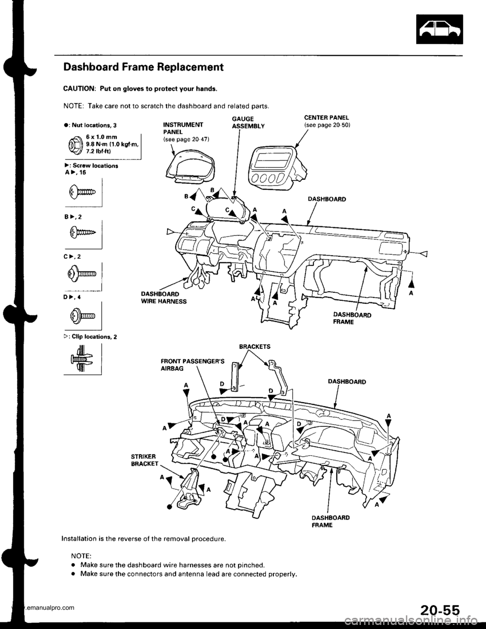
Dashboard Frame Replacement
CAUTION: Put on gloves to prolect your hands.
NOTE: Take care not to scratch the dashboard and related parts.
GAUGEa: Nut locations,3INSTRUMENTPANEL(see page 20 47)
\,.\
/ ,.-------f,\
lu /A
w
CENTER PANEL{see page 20 50)
6x1.0mm9.8 N.rn 11.0 kgf.m,7.2 tbt.ftl
>i Screw locationsA>,16
I
\,r*
B>,2
^l
S@t' 1-l
c >,2
I
0@l"l
D>.a
^l
0Fl-l
>: Clip localions.2
.dr IIhll'rifi- |-wr
i
DASHBOARDFRAME
DASHBOARDwlRE HARNESS
Installation is the reverse oI the removal orocedure.
NOTE:
. Make sure the dashboard wire harnesses are not Dinched.. Make sure the connectors and antenna lead are connected properly.
FRONT PASSENGER'S
www.emanualpro.com
Page 1221 of 1395
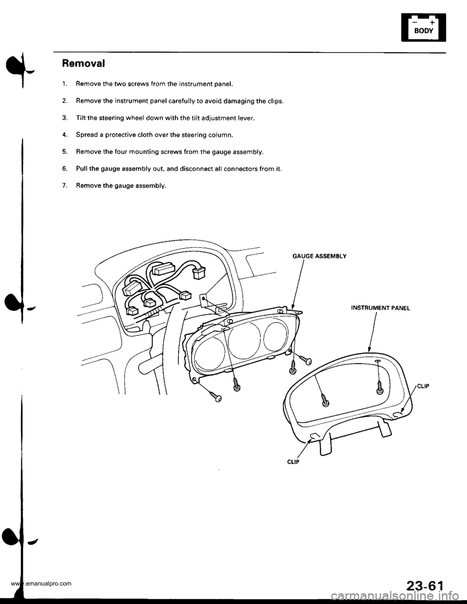
Removal
'1. Remove the two screws from the instrument panel.
2. Remove the instrument panel carefully to avoid damaging the clips.
3. Tilt the steering wheel down with the tilt adjustment lever.
4, Spread a protective cloth over the steering column.
5. Remove the four mounting screws from the gauge assembly.
6. Pullthe gauge assembly out, and disconnect all connectors from it.
7, Remove the gauge assembly.
GAUGE ASSEMELY
INSTRUMENT PANEL
23-61
www.emanualpro.com


