piston HONDA CR-V 1997 RD1-RD3 / 1.G User Guide
[x] Cancel search | Manufacturer: HONDA, Model Year: 1997, Model line: CR-V, Model: HONDA CR-V 1997 RD1-RD3 / 1.GPages: 1395, PDF Size: 35.62 MB
Page 124 of 1395
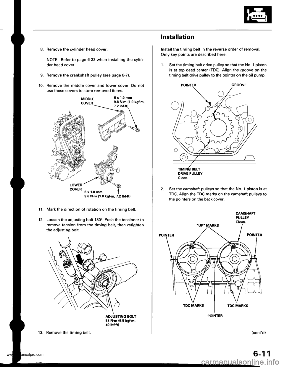
8. Remove the cylinder head cover.
NOTE: Refer to page 6-32 when installing the cylin-
der head cover.
Remove the crankshaft pulley (see page 6-7).
Remove the middle cover and lower cover. Do not
use these covers to store removed items.
9.
10.
11.
MTDDLE 6x1.0mm
COVER 9.8 N.m {1.0 kgt m,
LOWERCOVER
9.8 N.m (1.0 kgt.m, 7.2 lbf.ftl
Mark the direction of rotation on the timing belt.
Loosen the adjusting bolt 180'. Push the tensioner to
remove tension from the timing belt, then retighten
the adiusting bolt.
AINUSTING BOLT54 N.m (5,5 kgt m,.(} tbf.rrl
12.
13. Remove the timing belt.
Installation
Install the timing belt in the reverse order of removal;
Only key points are described here,
1. Set the timing belt drive pulley so that the No. 1 piston
is at top dead center (TDC). Align the groove on the
timing belt drive pulley to the pointer on the oil pump.
GROOVE
DRIVE PULLEYClean.
2. Set the camshaft pulleys so that the No. I piston is at
TDC. Align the TDC marks on the camshaft pulleys to
the pointers on the back cover.
POINTER
CAMSHAFTPULLEYClean.
POINTER
r-t
(cont'd)
6-11
www.emanualpro.com
Page 144 of 1395
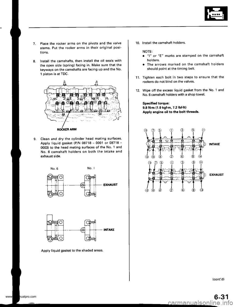
7.Place the rocker arms on the pivots and the valve
stems. Put the rocker arms in their original posi-
lrons.
lnstall the camshafts, then install the oil seals with
the open side (spring) facing in. Make sure that the
keyways on the camshafts are facing up and the No.
1 piston is at TDC.
Clean and dry the cylinder head mating surfaces.
Apply liquid gasket (P/N 08718 - 0001 or 08718 -
0OO3) to the head mating surfaces of the No. 1 and
No. 6 camshaft holders on both the intake and
exhaust side.
L
No. I
EXHAUST
II{TAKE
Apply liquid gasket to th€ shaded areas.
't't,
'10. lnstall the camshaft holders.
NOTE:
o "1" or "E' marks are stamped on the camshaft
holders.
. The arrows marked on the camshaft holders
should point at the timing belt.
Tighten each bolt in two steps to ensure that the
rockers do not bind on the valves.
Wipe off the excess liquid gasket from the No. 1 and
No. 6 camshaft holders with a shop towel,
Specified torque:
9.8 N.m (1.0 kgf.m, 7.2 lbf.ft)
Apply engine oil to the bolt ihreads.
I?,ITAKE
EXHAUST
(cont'd)
6-31
www.emanualpro.com
Page 145 of 1395

Cylinder Head
Installation (cont'dl
'13. Align the marks on the cylinder head plug to thecylinder head upper surface, then install the cylin
der head plug in the end of the cylinder head.
CYLINOER HEADPLUGReplace.
lnstallthe back cover.
To set the camshafts at TDC position for the No. lpiston, align the holes in the camshafts with theholes in the No. l camshaft holders and insert 5.0mm pin punches in the holes. Install the keys into
the camshaft grooves.
37 N m (3.8 *gl.m, 27 lbt.tr)
9.8 N.m (1.0 kgtm,7.2|hrftl
Push the camshaft pulleys onto the camshafts. thentighten the retaining bolts to the torque specified.
6-32
14.
KEYS
I x 1.25 mm
6x1.0mm
Install the timing belt (see page 6-1 1).
Adjust the valve clearance (see page 6-3).
Thoroughly clean the head cover gasket and thegroove.
lnstall the head cover gasket in the groove of thecylinder head cover. Seat the head cover gasket in
the recesses for the camshaft first, then work it into
the groove around the outside edges. Make sure thehead cover gasket is seated securely in the corners
of the recesses with no gap.
17.
'18.
19.
www.emanualpro.com
Page 147 of 1395
Engine Block
Speciaf Tools .............7-2
lllustrated lndex ................................... 7-3
Flywheel and Drive Plate
Replacement ..,.,....7-5
Connecting Rod and Grankshaft
End Play .................7-6
Main Bearings
Cfearance ...............7 -7
Selection ................7-8
Connecting Rod Bearings
Clearance ...............7-8
Selection ................7-9
Pistons and Crankshaft
Removal .................7-9
Crankshaft
Inspection .............. 7-11
Pistons
fnspection ..............7-12
fnstaflation .............7-20
Cylinder Block
Inspection ..............7-13
Piston Pins
Removal ..,.......,,..... 7-14
Installation ............. 7-15
Inspection .............. 7-16
Connecting Rods
Selection ................7 -14
Piston Rings
End Gap .................7 -17
Ring-to-Groove Clearance ............... 7 -17
Replacement .........7-18
Alignment .............. 7-18
Crankshaft Oil Seal
lnstallation ............. 7-19
Crankshaft
lnstalfation .............7-20
Oil Seals
fnstalfation ....,..,.....7-23
www.emanualpro.com
Page 148 of 1395
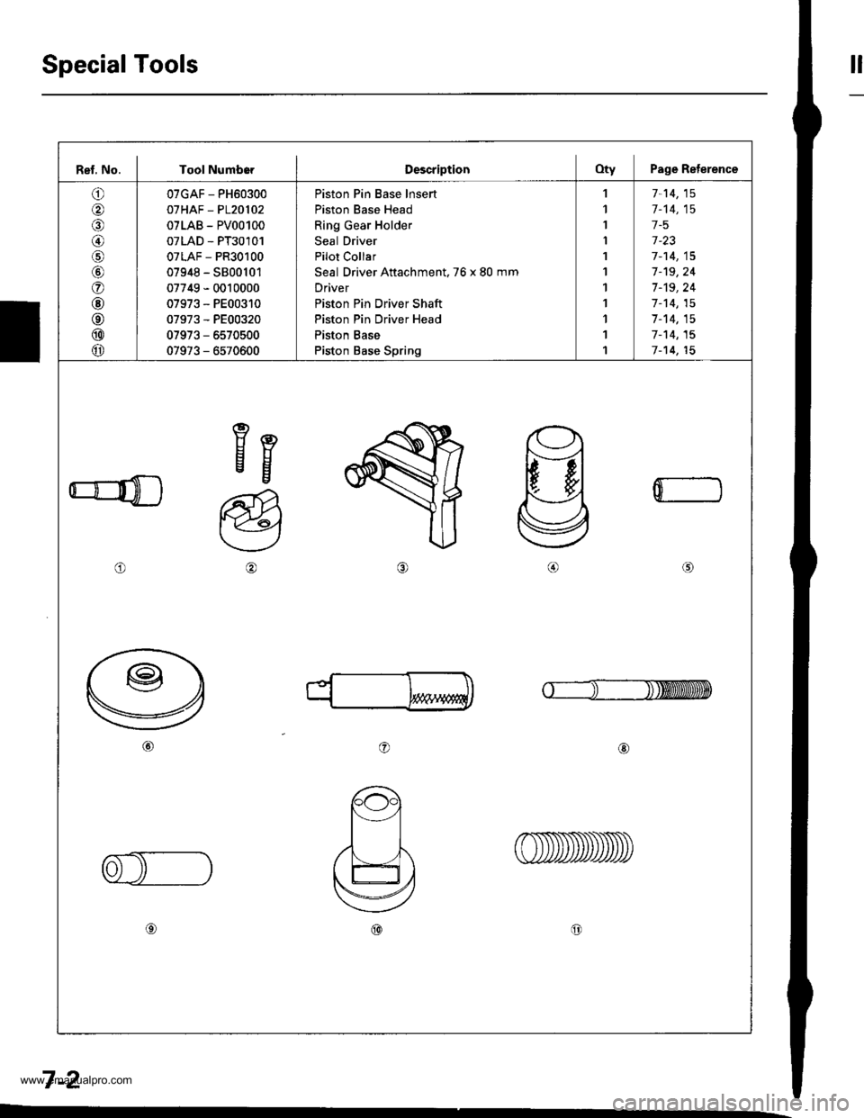
Special Toolstl
Ref, No. I Tool NumborDescriptionOty Page Reterence
o
@
@/6
@
o
@
@
@
@
07GAF - PH60300
07HAF - P120102
07LAB - PV00100
07LAD - PT30101
07LAF - PR30100
07948 - S800101
07749 - 0010000
07973 - PE00310
07973 - PE00320
07973 - 6570500
07973 - 6570600
Piston Pin Base lnsert
Piston Base Head
Ring Gear Holder
Seal Driver
Pilot Collar
Seal Driver Attachment. 76 x 80 mm
Driver
Piston Pin Driver Shaft
Piston Pin Driver Head
Piston Base
Piston Base Spring
,l
1
I
I
1
1
1
1
1
1
1
7-14,15
1-'t4,15
1-5
1-23
7-14,15
7-'t9,24
7 -'t9, 24
1-14,15
7-14,15
7-'t4,15
7-14,15
eEEg
o
a@
0
o@
7-2
www.emanualpro.com
Page 150 of 1395
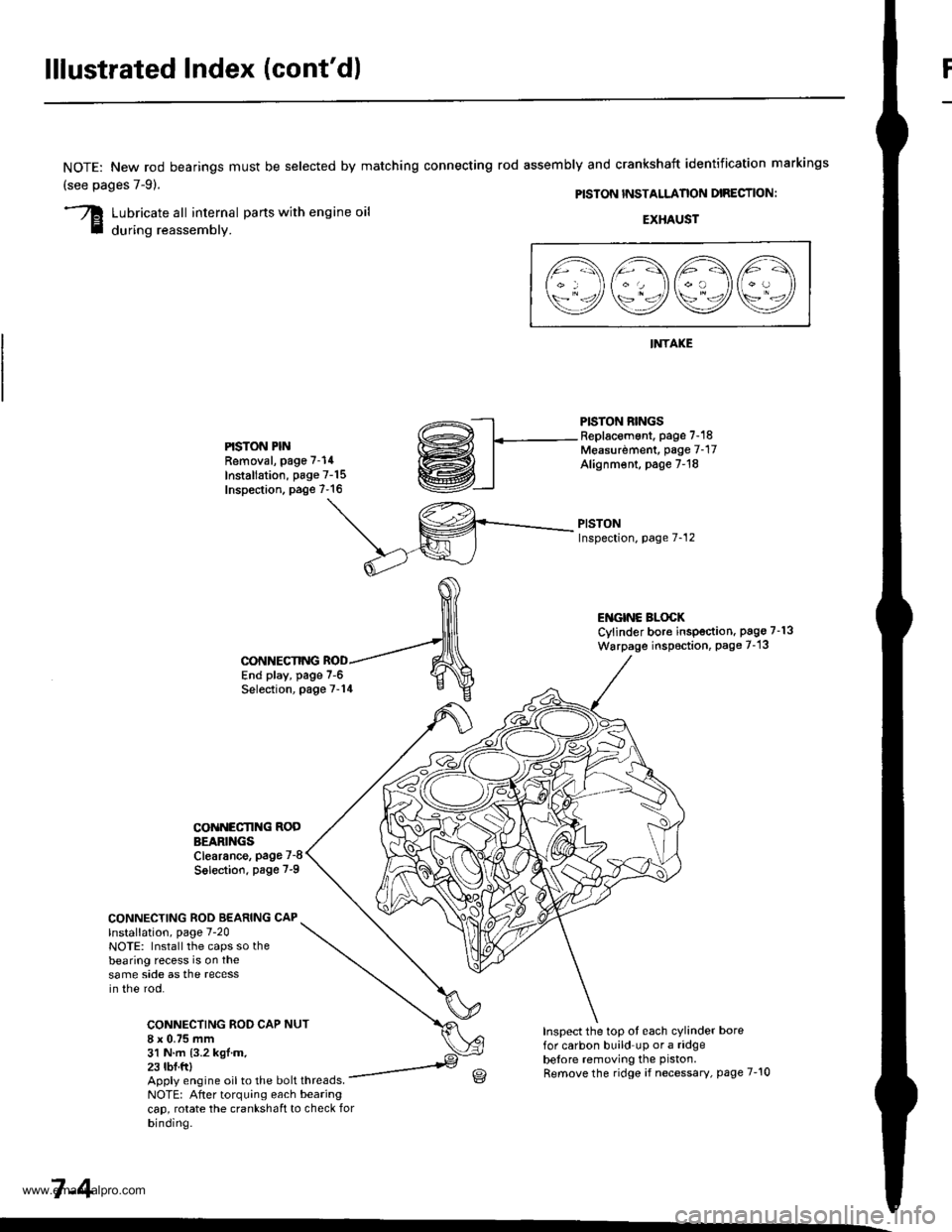
lllustrated Index (cont'd)
NOTE: New rod bearings
(see pages 7-91.
must be selected by matching connecting rod assembly and crankshaft identification markings
PISTON INSTALLANON DIRECTION:
Lubricate all internal parts with engine oil
during reassembly.EXHAUST
INTAKE
PISTON RINGSReplacement. page 7-18Measurdment, page 7-17Alignm€nt, page 7-18
PISTONInspection, page 7-12
l1\AAtr\
\9q9Q9e/
PISTON PINRemoval, page 7-14
Installation, page 7-15Inspection. page 7-16
ENGINC BLOCKCylinder bore inspection. pago 7-13
Warpage inspoction, Page 7-'13
CONNECTING ROD BEARING CAPlnstallation, page 7-20NOTE: Install the caps so thebearing recess is on thesame side as the recessin the rod.
CONNECTING ROD CAP8 x 0.75 mm31 N.m {3.2 kgl.m.23 tbf.ftl
CONNECTING
COiINECI'ING RODBEARINGSClearance, page 7-8
Solection. page 7-9
NUT
End play, page 7-6Selection, page 7-14
Inspect the top ot each cylinder borefor carbon build up or a ridgebelore removing the piston.
Remove the ridge if necessary, page 7-10Apply engine oil to the bolt threads.NOTE: After torquing each bearingcap, rotate the crankshaft to check forbinding.
7-4
www.emanualpro.com
Page 155 of 1395
Pistons and
Crankshaft
Selection
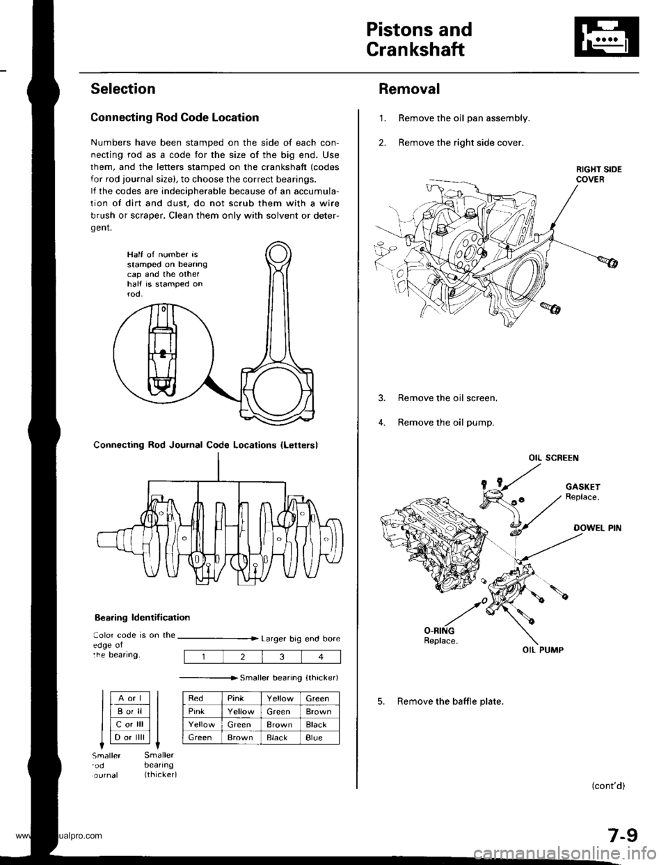
Connecting Rod Code Location
Numbers have been stamped on the side of each con-
necting rod as a code for the size of the big end. Use
lhem, and the letters stamped on the crankshaft (codes
for rod journal size), to choose the correct bearings.
lf the codes are indeciDherable because of an accumula-
tion of dirt and dust, do not scrub them with a wire
brush or scraper. Clean them only with solvent or deter-
gent.
8€aring ldentif ication
aolor code is on theedge oltne Deanng.
Larger big end bore
---------------r. sma er bearino {thicker)
RedPinkGreen
PinkGreenBrown
GreenBrownBlack
GreenBrownElackBlue
Half of number isstamped on beanngcap and the othelhalf is stamped onrod.
Connecting Rod Journal Code Locations {Lettersl
llAort ll
llBo'll ll
llcotrll ll
I l-.. ilril It-lSmaller'odSmallerbeanng(thicker)
234
Removal
Remove the oil pan assembly.
Remove the right side cover.
1.
Remove the oil screen.
Remove the oil pump.
OIL SCREEN
(cont'd)
7-9
OIL PUMP
5. Remove the baffle plate.
www.emanualpro.com
Page 156 of 1395
Pistons and Crankshaft
Removal (cont'dl
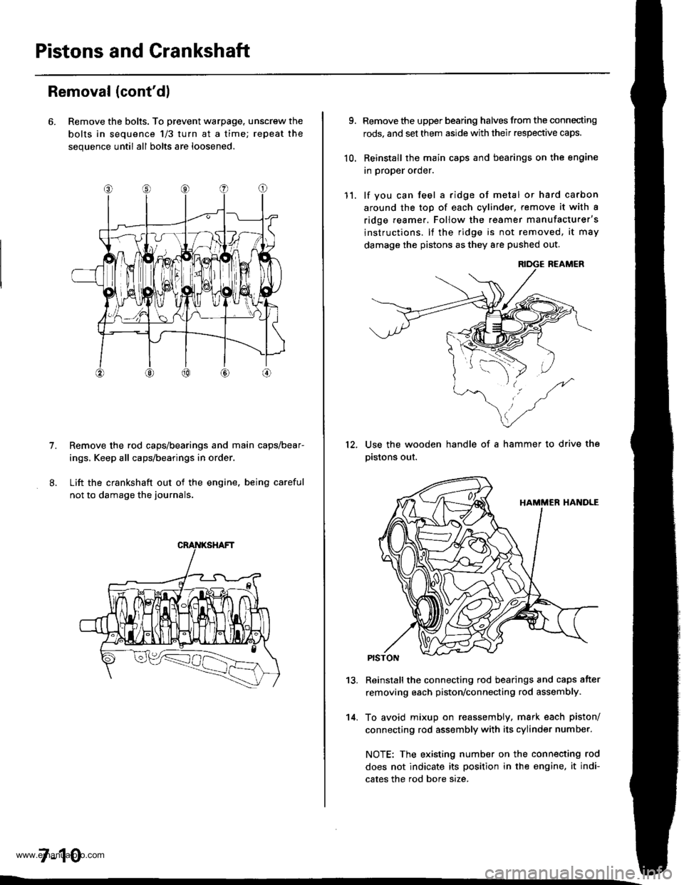
6. Remove the bolts. To prevent warpage, unscrew the
bolts in sequence 1/3 turn at a time; repeat the
sequence until all bolts are loosened.
Remove the rod caps/bearings and main caps/bear-
ings, Keep all caps/bearings in order
Lift the crankshaft out of the engine. being careful
not to damage the journals.
7.
7-10
9.
10.
Remove the upper bearing halves from the connecting
rods, and set them aside with their respective caps.
Reinstall the main caps and bearings on the engine
in proper order.
lf you can feel a ridge of metal or hard carbon
around the top of each cvlinder, remove it with a
ridge reamer. Follow the reamer manufacturer's
instructions. lf the ridge is not removed, it may
damage the pistons as they 8re pushed out.
12.
11.
14.
Use the wooden handle of a hammer to drive the
pistons out.
13.Reinstall the connecting rod bearings and caps after
removing each piston/connecting rod assembly.
To avoid mixup on reassembly, mark each piston/
connecting rod assembly with its cylinder number.
NOTE: The existing number on the connecting rod
does not indicate its position in the engine, it indi-
cates the rod bore size.
www.emanualpro.com
Page 158 of 1395
PistonsI
Inspection
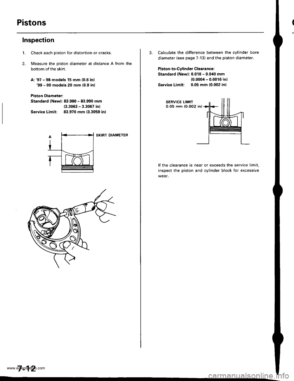
LCheck each piston for distortion or cracks.
Measure the piston diameter at distance A from the
bottom of the skirt.
A: '97 - 98 models 15 mm 10.5 inl'99 - 00 models 20 mm 10.8 inl
Piston Diameter:
Standard (New): 8:1.980 - txl.990 mm(3.3063 - 3.3067 inl
Service Limit: 83.970 mm {3.3059 inl
SKIRT DIAMETER
7-12
3. Calculate the difference between the cylinder bore
diameter (see page 7-13) and the piston diameter.
Piston-to-Cylinder Clearance:
Standard {New): 0.010 - 0.040 mm
{0.0004 - 0.0016 inl
Service Limit: 0.05 mm {0.002 in}
lf the clearance is near or exceeds the service limit,
inspect the piston and cylinder block for excessive
wear.
www.emanualpro.com
Page 160 of 1395
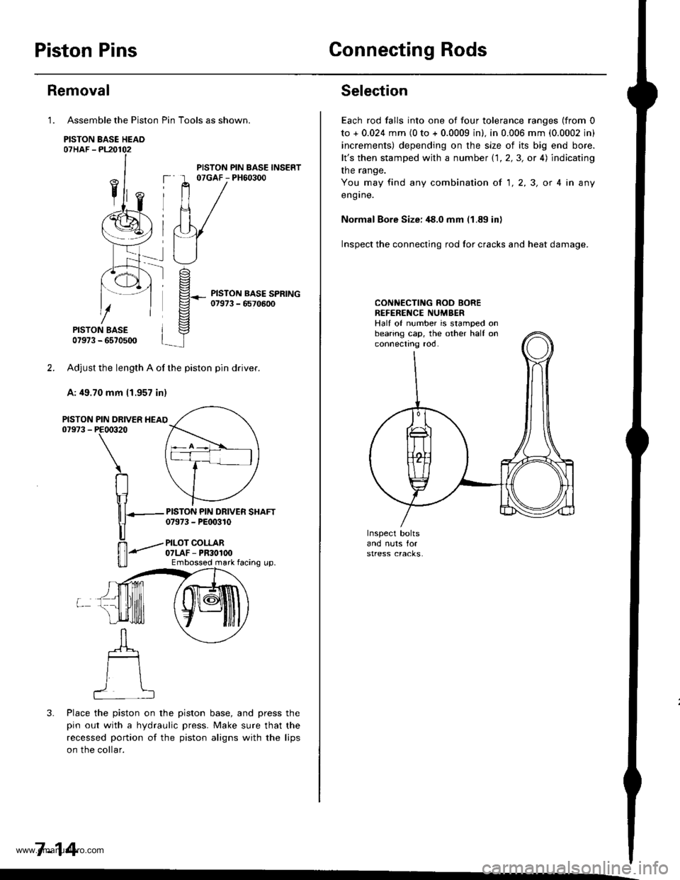
Piston PinsConnecting Rods
Assemble the Piston Pin Tools as shown.
PISTON BASE HEAO07HAF -PL20102
PISTON BASE07973 - 6570500
Adjust the length A of the piston pin dflver.
A: 49.70 mm 11.957 in)
PIN DRIVER HEAIPE00320
\
RIr1
nT---
u
ffi-"""-
u_ll
3. Place the piston on the piston base, and press the
pin out with a hydraulic press. Make sure that the
recessed portion of the piston aligns with the lips
on the collar.
7-14
Removal
1.
PISTON07973 -
PISTON PIN BASE INSERT07GAF - PH60300
PISTON PIN DRIVER SHAFT07973 - PEt 0310
PILOT COLLAR07LAF - PR30100Embossod mark facing up.
Selection
Each rod falls into one of four tolerance ranges (from 0
to + 0.024 mm {0 to + 0.0009 in). in 0.006 mm (0.0002 in)
increments) depending on the size of its big end bore.
lt's then stamped with a number 1.1.2,3, or 4) indicating
the range.
You may find any combination ot 1,2,3, or 4 in any
engrne.
Normal Bore Size: ,18.0 mm (1.89 in)
Inspect the connecting rod for cracks and heat damage.
CONNECTING ROD BOREREFENENCE NUMBERHalf of number is stamped onbearing cap, the other half onconnectno roo.
www.emanualpro.com