ignition HONDA CR-V 1997 RD1-RD3 / 1.G Workshop Manual
[x] Cancel search | Manufacturer: HONDA, Model Year: 1997, Model line: CR-V, Model: HONDA CR-V 1997 RD1-RD3 / 1.GPages: 1395, PDF Size: 35.62 MB
Page 1379 of 1395
Troubleshooting
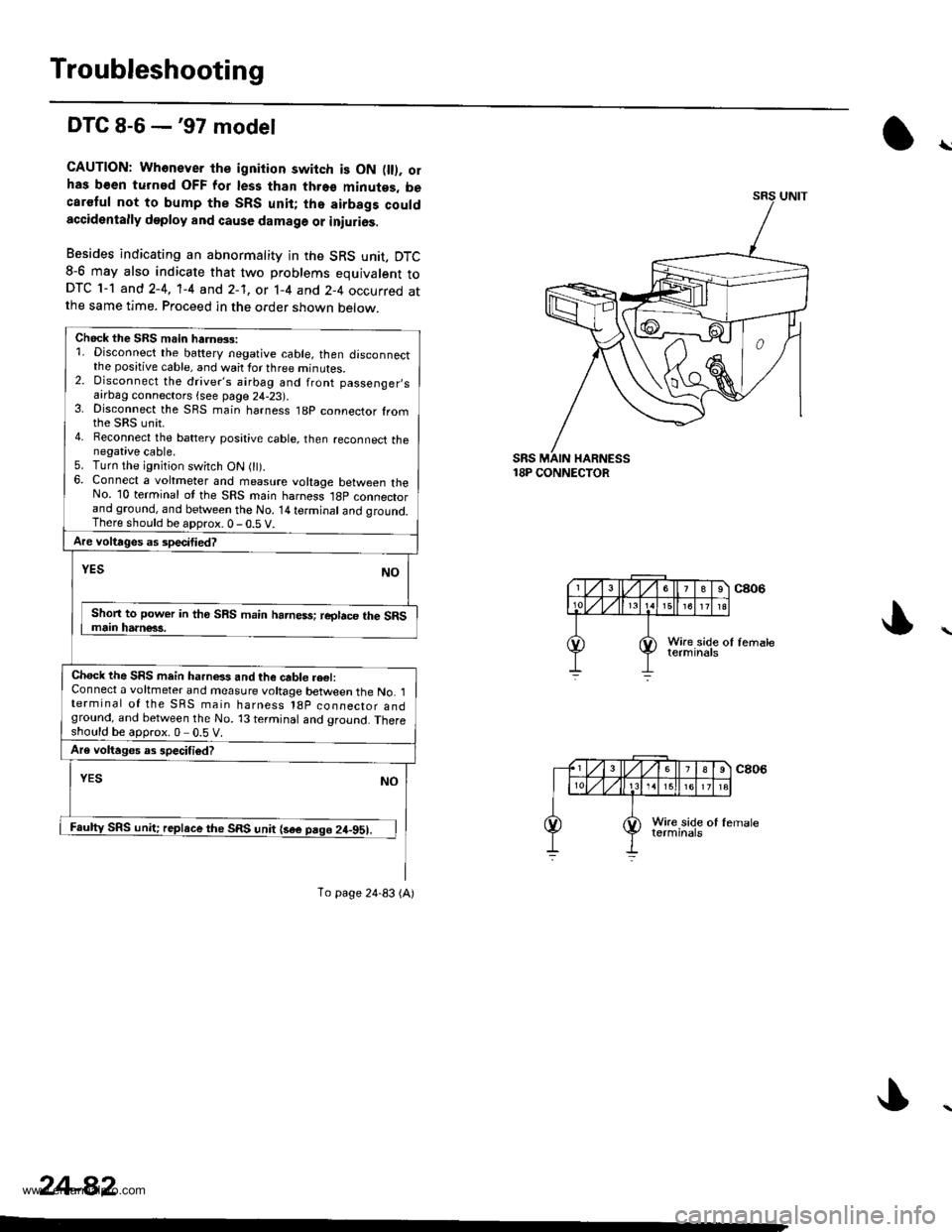
DTC 8-6 -'97 model
CAUTION: Whonever th€ ignition switch is ON fll). olhas b€en turned OFF for les3 than thro€ minutes, becaretul not to bump the SRS unit; tho airbags couldaccidentally deploy and cause damage or iniurios.
Besides indicating an abnormality in the SRS unit, DTC8-6 may also indicate that two problems equivalent toDTC 1-1 and 2-4, 'l-4 and 2-1, or 1-4 and 2-4 occurred atthe same time. Proceed in the order shown below.
18P CONNECTOR
\
Chock the SBS main harnGs:1. Disconnect the battery negative cable, then disconnectthe positive cable, and wait for three minutes.2. Disconnect the driver's airbag and front passenger,safrDag connectors {see page 24-23).3. Disconnect the SRS main harness t8p connector fromthe sRs unit.4. Reconnect the battery posative cable, then reconnect thenegative cable.5. Turn the ignition switch ON 0t).6. Connect a voltmeter and measure voltage between theNo. 10 terminal ot the SRS main harness l8p connectorand ground, and between the No. 14 terminal and qround.There should be aDorox.0-0.5 V.
Are voltages as specitied?
NOYES
Shon to power in tho SRS main harness; reglace the SRSmain harn€63.
Chock the SRS mein harnels and the cable re€l:Connect a voltmeter and measure voltage between the No. 1terminal of the SRS main harness l8p coonector andground, and between the No. 13 terminal and ground. Thereshould be approx.0 0.5 V.
Are voltages as specifiod?
YESNO
Faulty SRS unit; replace the SRS unit {sae pago 24-951.
To page 24-83 (A)
24-82
www.emanualpro.com
Page 1380 of 1395
)
)
From page 24-82 iA)
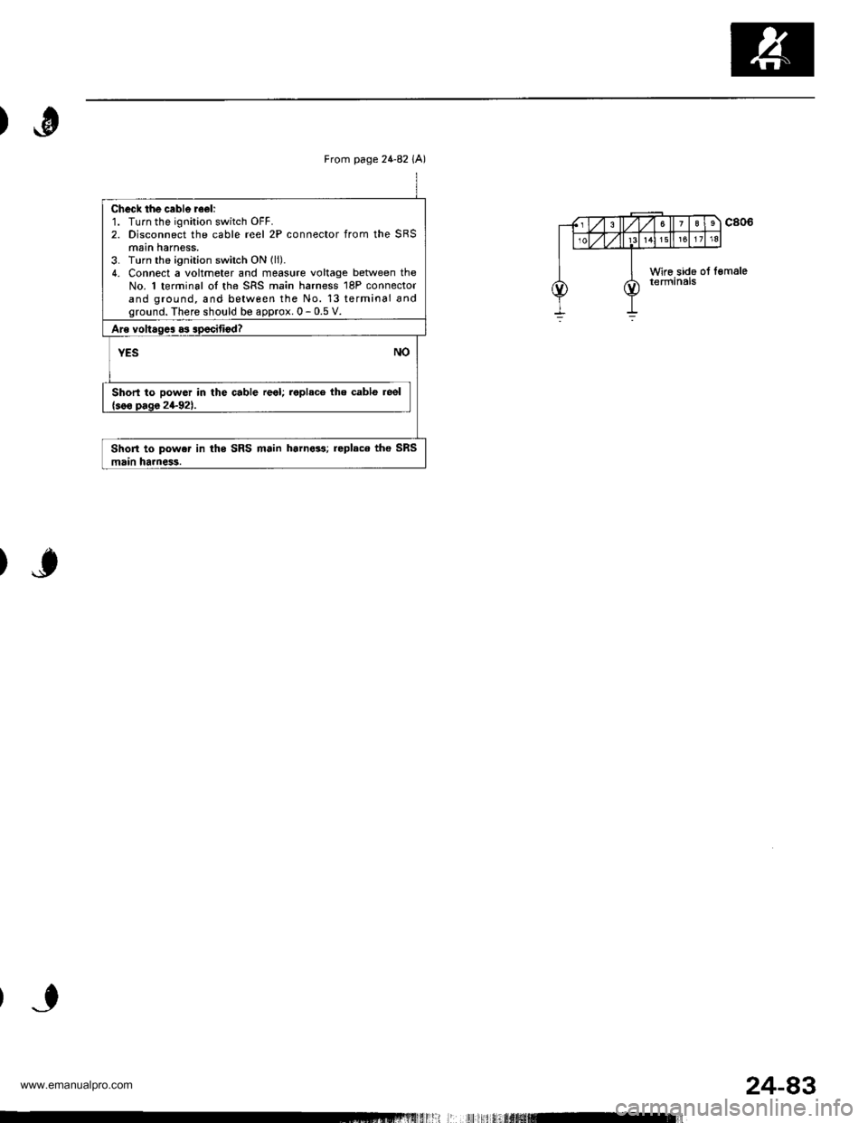
Check the cable reeli1. Turn the ignition switch OFF.2. Disconnect the cable reel 2P connector from the SRSmain harness,3. Turn the ignition switch ON lli).4. Connect a voltmeter and fieasute voltage beNveen theNo. 'l terminal oI the SRS main harness 18P connectorand ground, and between the No. 13 terminal andground. There should be approx. 0 - 0.5 V.
Are voltagcs as specifiod?
YESNO
Short to powor in the cable reel; replace the cable reel{soo oaqa 24-921.
Short to powe. in ths SRS main harn633; replaco tho SRSmain harness.
Lll l| i,ltufiffifil-]ll
24-83
www.emanualpro.com
Page 1381 of 1395
Troubleshooting
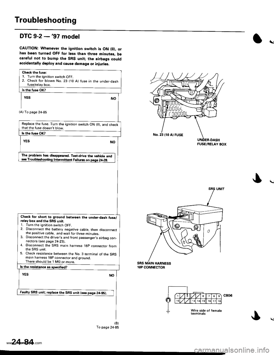
DTC 9-2 -'97 model
CAUTION: Whenever the ignition switch is ON flll, orhas been turned OFF tor loss than thrse minute3, bscareful not to bump the SRS unit; lhe airbags couldaccidentally doploy and causo damage or iniuriss.
\
Ch6ck the tuso:1. Turn the ignition switch OFF.2. Check tor blown No. 23 (10 A) fuse in the !nder-dashIuse/relay box.
Replace the fuse. Turn the ignition switch ON {ll}, and ch€ckthat the fuse doesnt blow.
Tho problem has dilappeared. T6t-drive the vohid€ andsee Troubl6hogting Intermittedt Failur6 on prgc 2il-2g.
Check for shon to ground botween the undor-darh fu36,/relay box and tho SRS unit.1. Turn the ignition switch OFF.2. Disconnect the battery negative cable, then disconnectthe positive cable, and wait for three minutes.3. Disconnect the driver's and front passenger,s airbag con-nectors {see page 24,23).4. Disconnect the SRS main harness 18p connector from
5. Check resistance between the No. 3 terminal of the SFSmain harness 18P connector and grouncl.There should be 1 M0 or more.
Faufty SRS unit; replaco th6 SRS unit {3e€ page 2t-951.
(A) To page 24-85
To page 24-85
No. 23 110 Al FUSE
FUSE/RELAY BOX
sRs18P CONNECTOR
24-84
www.emanualpro.com
Page 1382 of 1395
from page 24'84(B)
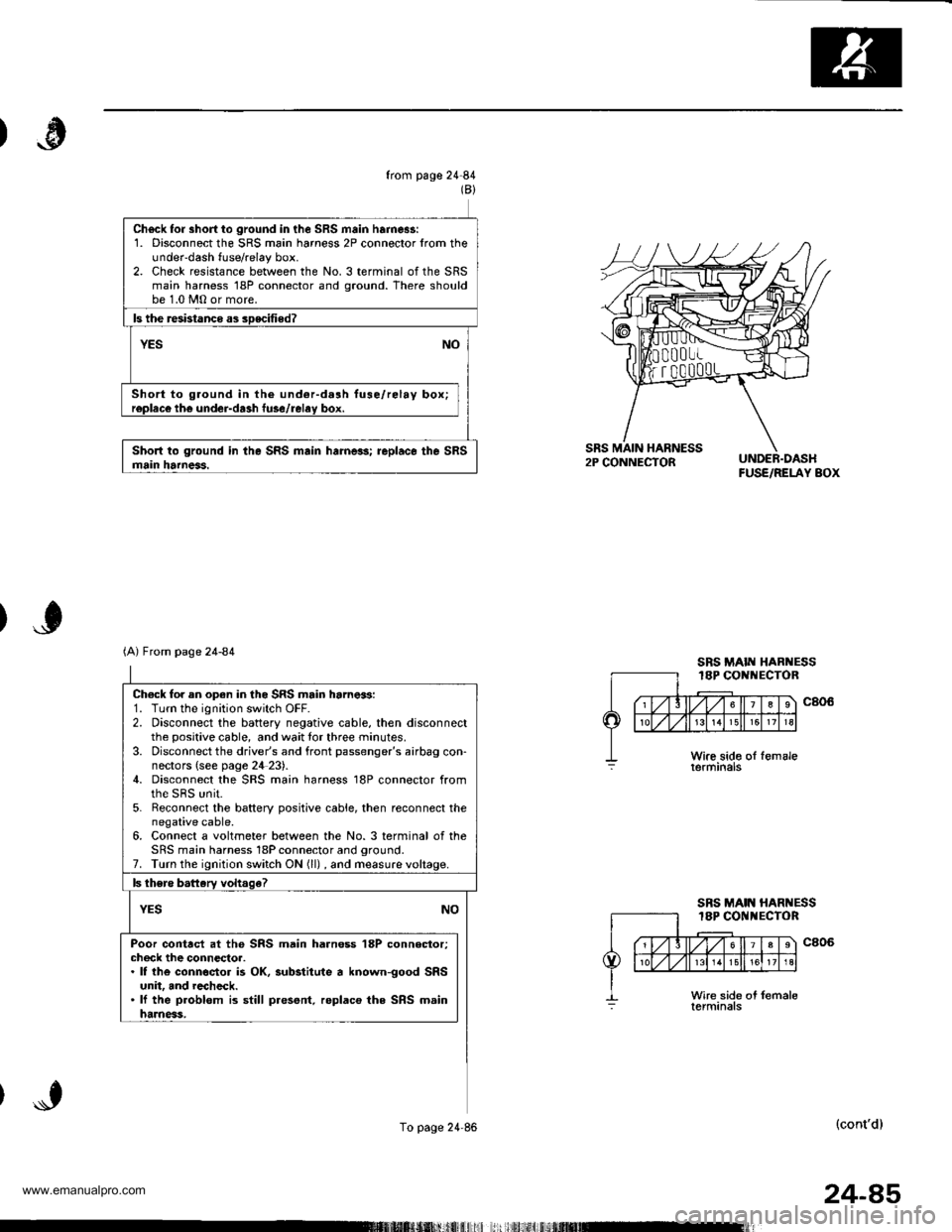
Ch6ck fo. short io ground in the SRS main harnes!:1. Disconnect the SRS main harness 2P connector lrom theunder-dash fuse/relay box.2. Check resistance between the No. 3 terminal of the SRSmain harness 18P connector and ground. There shouldbe 1.0 MO or more.
ls the resbtanco as soecitied?
YESNO
Short to ground in the undor-dalh fuse/relay box;r€placo th€ under-da3h fuse/relav box.
Short to ground in the SRS main harneas; replaco the SRSmain harneas.FUSE/RELAY BOX
Ch€ck for an open in the SRS main harnes:1. Turn the ignition switch OFF.2. Disconnect the battery negative cable, then disconnectthe positive cable, and wait tor three minutes.3. Disconnect the driver's and front passenger's airbag con-nectors {see page 2il 23).4. Disconnect the SRS main harness 18P connector fromthe sRs unit.5. Reconnect the baftery positive cabie, then reconnect thenegative cable.6. Connect a voltmeter between the No. 3 terminal of theSRS main harness 18P connector and oround.7. Turn the ignition switch ON (ll) , and measure
Poor contrct at the SRS main harn€ss 18P connector;check the connectoa.. lf the connsctor is OK, substitute a known-good SRSunit, and rccheck.. lf the problom is still present. replaco the SRS mainharness,
(A) From page 24-84
To page 24'86
SRS MAIN HARNESS18P CONI{ECTOR
SBS MAIN HARNESS18P COI{l{ECTOR
(cont'd)
24-85
www.emanualpro.com
Page 1383 of 1395
Troubleshooting
DTC 9-2 -'97 model lcont'dl
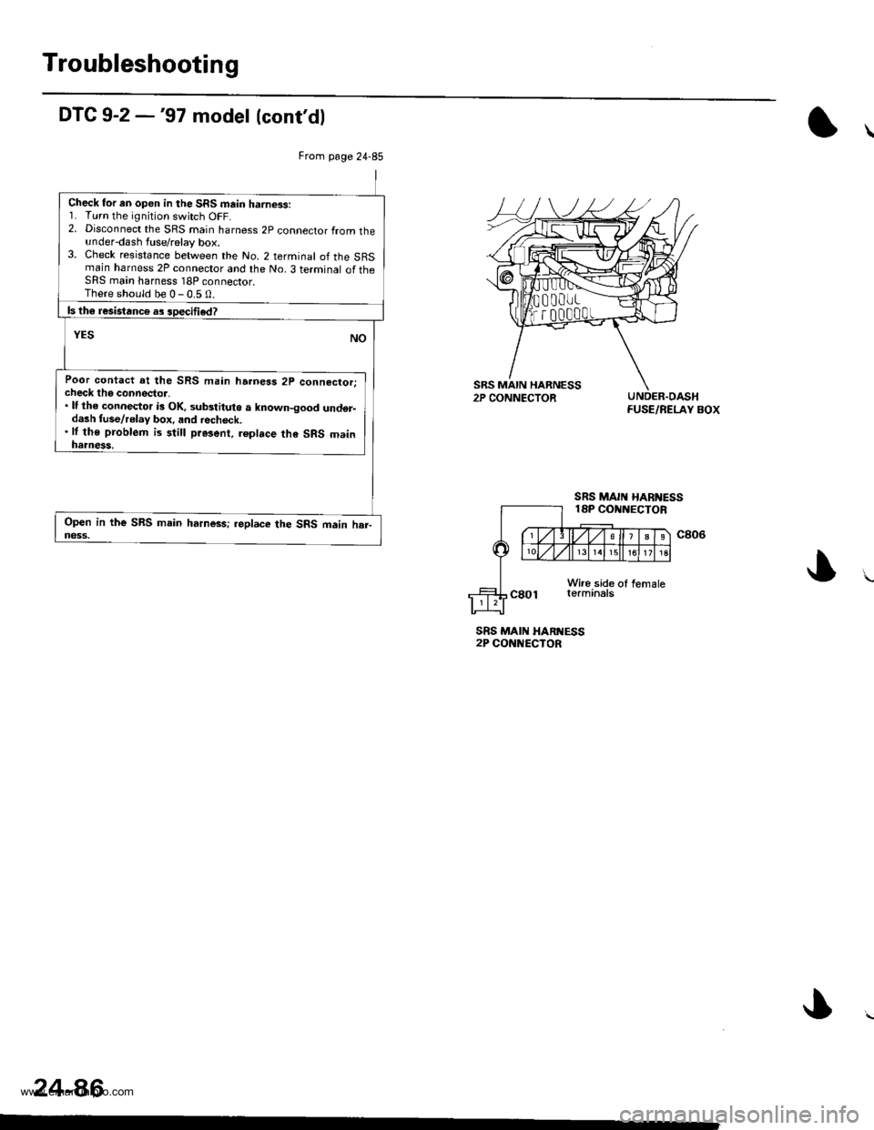
UNDER.OASHFUSE/RELAY BOX
SRS MAII{ HARI{ESS2P CONNECTOR
24-86
From page 24-85
Check for an open in the SRS main harness:1. Turn the ignition switch OFF.2. Disconnect the SRS main harness 2p connector from theunder-dash fuse/relay box.3. Check resistance between the No. 2 terminal of the SRSmain harness 2P connector and the No. 3 terminal of theSRS main harness 18P connector.There should be 0-0.5 0.
ls th6 resistance as soecified?
YESNO
Poor contact at the SRS main harness 2p connector;check tho connector,. lf the connector i3 OK, substituto a known-good und€r-dash fuse/relay box, and recheck.. lf the problem is still present, roplace the SRS mainnatness,
Open in the SRS main harn$s;.eplace the SRS main har-ness.
www.emanualpro.com
Page 1385 of 1395
Driver's Airbag
Replacement lcont'd)
CAUTION: 8. sure to instattthe SRS wiring so that it isnot plnched or inlerfsring with other parts.
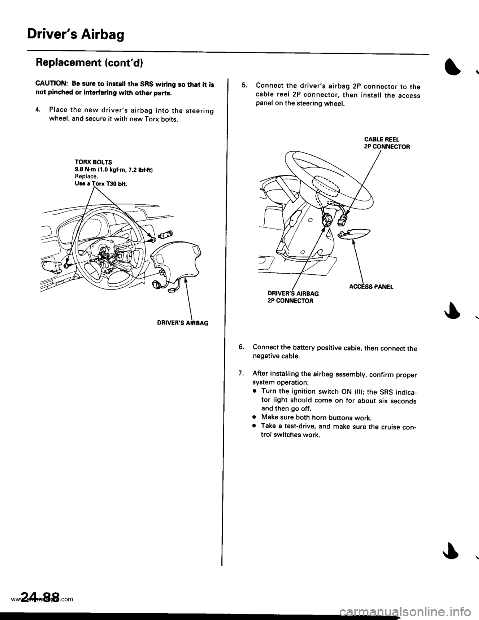
4. Place the new driver's airbag into the steeringwheel, and secure it with new Torx bolts.
TORX EOLTS9.8 N,m 11.0 kgl.m, 7.2 tbf,ftlFeplace.
24-88,
5. Connect the driver's airbsg 2p connector to thecable reel 2P connector, then install the accesspanel on the steering wheel.
Connect the battery positive cable. then connect thenegative cable.
After installing the airbag assembly, confirm proper
system operation:
. Turn the ignition switch ON llt); the SRS indica-tor light should come on for about six secondsand then go off.. Mske sure both horn buttons work.o Take a test-drive, and make sure the cruise con-trol switches work.
7.
2P CONNECTOR
www.emanualpro.com
Page 1387 of 1395
Front Passenger's Airbag
Replacement (cont'd)
GAUTION: Be sure to installthe SRS wiring so that it isnot pinched or interfering with olher parts.
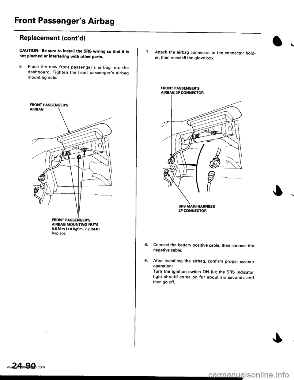
6. Place the new front passenger's airbag into thedashboard. Tighten the front passenger,s airbagmountrng nuts.
FRONT PASSENGER'SAIRBAG MOUNTING NUTS9.8 N.m {1.0 kgJ.m,7.2 lbf ft)Replace.
FRONT PASSENGER'S
24-90
7. Attach the airbag connector to the connector hold_er, then reinstall the glove box.
Connect the b8ttery positive cable, then connect thenegative cable.
After installing the airbag. confirm proper sysremooerauon:
Turn the ignition switch ON ( ); the SRS indicatorlight should come on for about six seconds andthen go off.
FRONT PASSENGER'S
www.emanualpro.com
Page 1391 of 1395
Cable Reel
16.
Replacement (cont'dl
11.
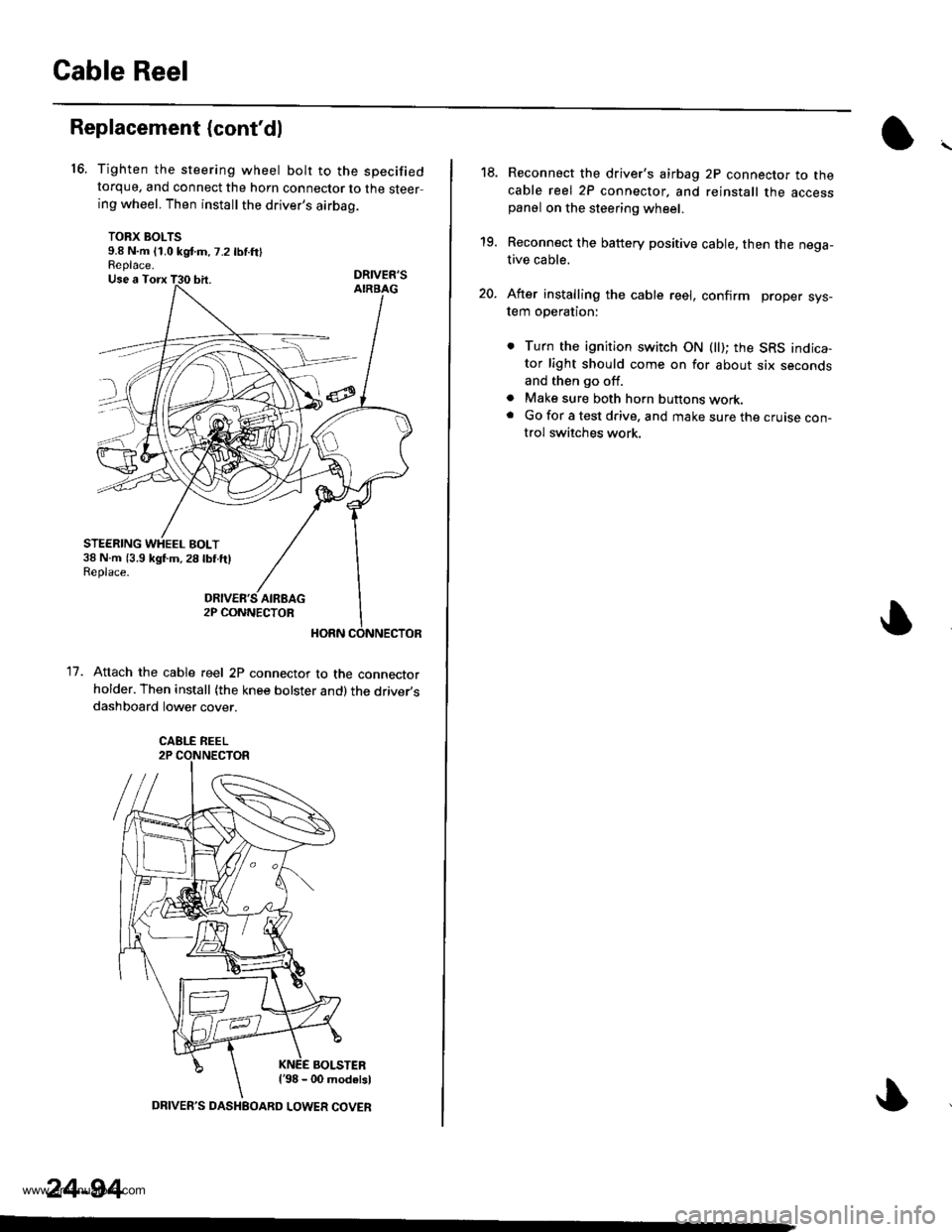
Tighten the steering wheel bolt to the specifiedtorque, and connect the horn connector to the steering wheel. Then install the driver's airbag.
TORX BOLTS9.8 N.m (1.0 kgd.m,7.2 lbnftlReplace.DRIVER'S
Attach the cable reel 2P connector to the connectorholder. Then install (the knee bolster and)the driver,sdashboard lower cover.
BOLSTERl'98 - 00 modalsl
STEERING WHEEL BOLT38 N.m (3.9 kgl.m,28lbf.ftlReplace.
CABLE REEL
24-94
DRIVER'S DASHEOARD LOWER COVER
19.
20.
Reconnect the driver's airbag 2P connector to thecable reel 2P connector, and reinstall the accesspanel on the steering wheel.
Reconnect the battery positive cable, then the nega-tive cable.
After installing the cable reel, confirm proper sys-tem operation:
. Turn the ignition switch ON (ll); the SRS indica-tor light should come on for about six secondsand then go off.
a Make sure both horn buttons work.. Go for a test drive. and make sure the cruise con-trol switches work.
www.emanualpro.com
Page 1393 of 1395
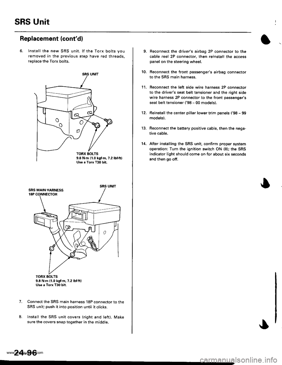
SRS Unit
Replacement (cont'dl
6. lnstall the new SRS unit. lf the Torx bolts you
removed in the previous step have red threads,
replace the Torx bolts.
TORX BOLTS9.8 N.m 11.0 kgf.m,7.2 lbtft)Uso a Torx T30 bit.
Connect the SRS main harness l8P connector to the
SRS uniu push it into position until it clicks.
Install the SRS unit covers (right and left). Make
sure the covers snap together in the middle.
7.
8.
TORX BOLTS9.8 N.m {1.0 kgf.m, ?.2Use . Torx T30 bh,
SRS UNIT
24-96
-
9. Reconnect the driver's aibag 2P connector to the
cable reel 2P connector, then reinstall the access
panel on the steering wheel.
Reconnect the front passenger's airbag connector
to the SRS main harness.
Reconnect the left side wire harness 2P connector
to the driver's seat belt tensioner and the right side
wire harness 2P connector to the front passenger's
seat belt tensioner ('98 - 00 models).
Reinstall the center pillar lower trim panels {'98 - 99
modelsl.
Reconnect the battery positive cable, then the nega-
tive cable.
After installing the SRS unit, confirm proper system
operation: Turn the ignition switch ON (ll); the SRS
indicator light should come on for about six seconds
and then go off,
10.
1't.
12.
13.
14.
www.emanualpro.com