Motor HONDA CR-V 1997 RD1-RD3 / 1.G Owner's Manual
[x] Cancel search | Manufacturer: HONDA, Model Year: 1997, Model line: CR-V, Model: HONDA CR-V 1997 RD1-RD3 / 1.GPages: 1395, PDF Size: 35.62 MB
Page 672 of 1395

Symptom-to-Com ponent Chart
Hydraulic System (cont'd)
NOTES
See flushing procedure, page l4-264 and 265,
BSet idle rpm in gear to specified idle speed. lf still no good, adjust motor mounts as outlined in enginesection of this manual.
clf the large clutch piston O-ring is broken, inspect the piston groove for rough machining.
Dlf the clutch pack is seized or is excessively worn. inspect the other clutches fot wear, and check the orificecontrol valves, CPC valve, and linear solenoid for free movement.
lf the linear solenoid is stuck, inspect the clutches for wear.
lf the 1-2 shift valve is stuck closed. the transmission will not upshift. lf stuck open, the transmission hasno lst gear.
Hlf the 2nd orifice control valve is stuck, inspect the 2nd and 3rd clutch Dacks for wear.
lf the 3-4 orifice control valve is stuck, inspect the 3rd and 4th clutch packs for wear.
Jlf the clutch pressure control valve is stuck closed. the transmission will not shift out of lst gear.
Klmproper alignment of main valve body and torque converter housing may cause ATF pump seizure. Thesymptoms are mostly an rpm-related ticking noise or a high-pitched squeak.
Llf the ATF strainer is clogged with particles of steel or aluminum, inspect the ATF pump and differentialpinion shaft. lf both are OK and no cause for the contamination is found, replace the torque converter.
Mlf the lst clutch feed pipe guide in the end cover is scored by the mainshaft. inspect the ball bearing forexcessive movement in the transmission housing. lf oK, replace the end cover as it is dented. The o-rinounder the guide is probably worn.
N' Replace the mainshaft if the bushing for the 4th feed pipe is loose or damaged, lf the 4th feed pipe is darrFaged or out of round. replace the end cover.' Replace the mainshaft if the bushing for the l st feed pipe is loose or damaged. lf the 1st feed pipe is dam-aged or out of round, replace it.
oA worn or damaged sprag clutch is mostly a result of shifting the transmission in E!. E, or E positionwhile the wheels rotate in reverse. such as rocking the vehicle in snow.
PInspect the frame for collision damage.
lnspect for damage and wear:
l. Reverse selector gear teeth chamfers.
2. Engagement teeth chamfers of countershaft 4th and reverse gear.
3. Shift fork for scuff marks in center.
4. Differential pinion shaft for wear under pinion gears.
5. Bottom of 3rd clutch for swirl marks.
Replace items 1, 2, 3. and 4 if worn or damaged. lf transmission makes a clicking, grinding, or whirring noise,also replace mainshaft 4th gear, reverse idler gear, and countershaft 4th gear in addition to 1,2, 3, or 4.lf differential pinion shaft is worn, overhaul differential assembly, replace ATF strainer, and thoroughly cjeantransmission, flush torque converter. cooler, and lines,lf bottom of 3rd clutch is swirled and transmission makes gear noise. replace the countershaft and final drivenoear,
Be very careful not to damage the torque converter housing when replacing the main ball bearing. you
may also damage the ATF pump when you torque down the main valve body. This will result in ATF pumpseizure if not detected. Use the Drooer tools.
SInstall the main seal flush with the torque converter housing. lf you push it into the torque converterhousing until it bottoms out, it will block the fluid return passage and result in damage.
www.emanualpro.com
Page 948 of 1395
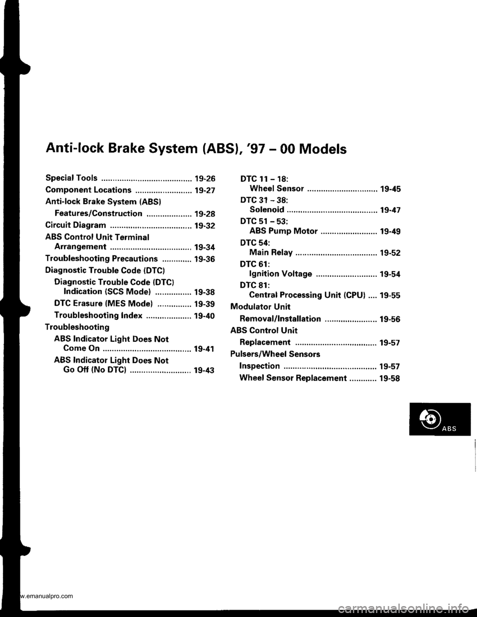
Anti-lock Brake System (ABSI,'97 - 00 Models
Special Tools ............. 19-26
Component Locations ......................... 19-27
Anti-lock Brake System (ABS)
Features/Construction ............. ......, 19-2A
Circuit Diagram ......... 19-32
ABS Control Unit Terminal
Arrangement ......... 19-34
Troubleshooting Precautions ............. 19-36
Diagnostic Trouble Gode (DTC)
Diagnostic Trouble Code (DTC)
Indication (SCS Model ................ 19-38
DTG Erasure (MES Mode) ............... 19-39
Troubleshooting lndex .................... 19-40
Troubleshooting
ABS Indicator Light Does Not
Come On ............ 19-41
ABS Indicator Light Does Not
Go Off (No DTC) ........................... 19-43
DTC 1r - 18:
Wheel Sensor .... 19-45
DTC 31 - 38:
Solenoid ............. 19-47
DTC 51 - 53:
ABS Pump Motor ......................... 19-49
DTC 54:
Main Relay ......... 19-52
DTC 61:
lgnition Voltage ........................... 19-54
DTC 81:
Central Processing Unit (CPU) .... 19-55
Modulator Unit
Removal/lnstallation ....................... 19-56
ABS Control Unit
Replacement ..,...... 19-57
Pulsers/Wheel Sensors
Inspection .............. 19-57
Wheel Sensor Replacement ............ 19-58
www.emanualpro.com
Page 950 of 1395
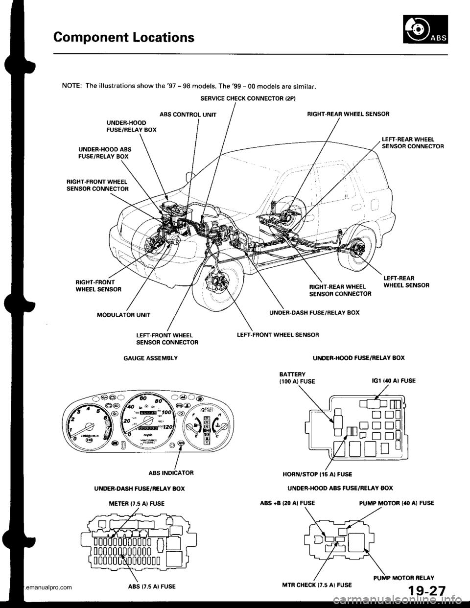
Component Locations
NOTE: The illustrations show the '97 - 98 models. The '99 - 00 models are similar.
ABS CONTROL UNITRIGHT-REAR WHEEL SENSOR
UNDER.HOOD ABSFUSE/RELAY BOX
RIGHT.FRONT WHEELSENSOR CONNECTOR
RIGHT-FRONTWHEEL SENSORRIGHT-REAB WHEELSENSOR CONNECTOR
MODULATOR UNIT
LEFT.FRONT WHEEL SENSOB
UNDER.DASH FUSE,/RELAY 8OX
UNDER.HOOO FUSE/RELAY AOX
IGl I(, AI FUSE
ABS +B 120 Al FUSEPUMP MOTOR ('II AI FUSE
HOBN/STOP I15 AI FUSE
UNDER.HOOD ABS FUSE/RELAY BOX
LEFT.FRONT WHEELSENSOE CONNECTOR
GAUGE ASSEMBLY
ABS INDICATOR
UNDER-DASH FUSE/NELAY BOX
METER {7.5 AI FUSE
MOTOR RELAY
19-27
SERVICE CHECK CONNECTOR {2PI
D!
trtrtr
[r D!
ABS {7.5 AI FUSEMTR CHECK 17.5 AI FUSE
www.emanualpro.com
Page 953 of 1395
Anti-lock Brake System (ABS)
Features/Gonstruction (cont'd)
ABS Modulator
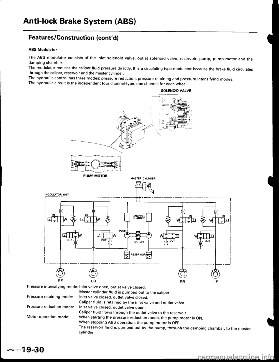
The ABS modulator consists of the inlet solenoid valve, outlet solenoid valve, reservoir, pump, pump motor and thedampjng chamber.
The modulator reduces the caliper fluid pressure directly. lt is a circulating-type modulator because the brake fluid circulatesthrough the caliper, reservoir and the master cylinder.The hydraulic control has three modes: pressure reduction, pressure retaining and pressure intensifying modes.The hydraulic circuit is the independent four channel-type, one channel for each wheel.
SOLENOID VALVE
t-
Pressure intensifying mode: Inlet valve open, outlet valve closed,
Pressure retaining mode:
Pressure reduction mode:
Motor operation mode:
Master cylinder fluid is pumped out to the caliper.Inlet valve closed, outlet valve closed.
Caliper fluid is retained by the inlet valve and outlet valve.Inlet valve closed, outlet valve ooen
Caliper fluid flows through the outlet valve to the reservoir.When starting the pressure reduction mode. the pump motor is ON.When stopping ABS operation, the pump motor is OFF.The reservoir fluid is pumped out by the pump, through the damping chamber, to the mastercylinder.
PUMP MOTOR
19-30
www.emanualpro.com
Page 954 of 1395
Wheel Sensor
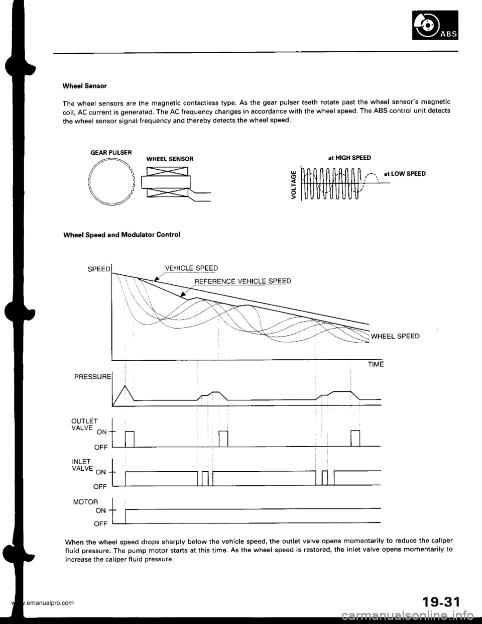
The wheel sensors are the magnetic contactless type. As the gear pulser teeth rotate past the wheel sensor's magnetic
coil, AC current is generated. The AC frequency changes in accordance with the wheel speed. The ABS control unit detects
the wheel sensor signal frequency and thereby detects the wheel speed
at LOW SPEED
wheel Sp€od and Modulatot Control
VEHICLE SPEED
VEHICLE SPEED
WHEEL SPEED
PRESSU
OUTLETVALVE ON
OFF
INLETVALVE ON
OFF
MOTOR
ON
OFF
When the wheel speed drops sharply below the vehicle speed, the outlet valve opens momentarily to reduce the caliper
fluid pressure. The pump motor starts at this time. As the wheel speed is restored. the inlet valve opens momentarily to
increase the caliDer fluid oressure.
F
GEAR PULSER
19-31
www.emanualpro.com
Page 955 of 1395
![HONDA CR-V 1997 RD1-RD3 / 1.G Owners Manual
Circuit Diagram
UNDFS I]OOD FISAFELAY 8OXCbsod: &rrc ped. deprelled
wHT/GrN -tjF GFrlrrvril
GNITION
*oJG\*"\€F*,-
UNDER-HOOD A8S FUSE/FELAY BOX3P CONNECTOR (O number)
t_--t l-|ll"1
UNDER.HOOO A8 HONDA CR-V 1997 RD1-RD3 / 1.G Owners Manual
Circuit Diagram
UNDFS I]OOD FISAFELAY 8OXCbsod: &rrc ped. deprelled
wHT/GrN -tjF GFrlrrvril
GNITION
*oJG\*"\€F*,-
UNDER-HOOD A8S FUSE/FELAY BOX3P CONNECTOR (O number)
t_--t l-|ll"1
UNDER.HOOO A8](/img/13/5778/w960_5778-954.png)
Circuit Diagram
UNDFS I]OOD FISAFELAY 8OXCbsod: &rrc ped. deprelled
wHT/GrN -tjF GFrlrr'vril
GNITION
*oJG\'*"\€F*,-
UNDER-HOOD A8S FUSE/FELAY BOX3P CONNECTOR (O number)
t_--t l-|ll'"1
UNDER.HOOO A8S FUSE/RELAY BOX2P CONNECTOF (! numbor)
EFIAKE SWITCH CONNECTOR
l€-4| 1 txl2 |
f s a'lLr--'--.----1
UNDER,DASH FUSFJRELAY BOX20P CONNECTOR (O number)M-OD U LATOR UN IT CON N ECTOR
ll3 2ir I
{tT6TsF}
!]q:]j_1,
MP MOTOR CONNECTORnumber)
ATi)
PU
UNDER-DASH FUSE/RELAY BOX18P CONNECTOR (E number)
(tr
ASSEMBLY 5P CONNECTOR
----.4-l1)/l3l/l5l
356J89
10111213,/ 115 ,/19
123456
910'1213|i4 /718
19-32
Wire side ol female lerminals
Terminal side oJ lemale terminals
www.emanualpro.com
Page 957 of 1395
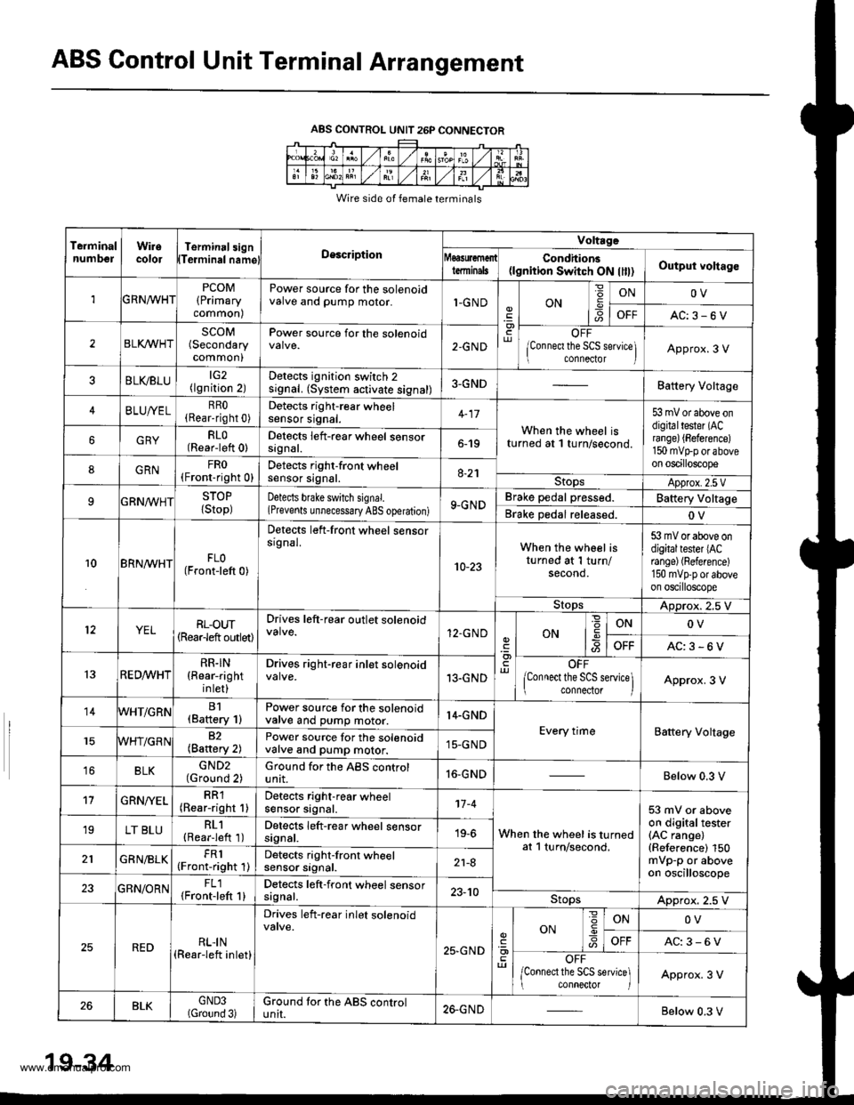
ABS Control Unit Terminal Arrangement
ABS CONTROL UNIT 26P CONNECTOR
Wire side of female terminals
TeiminalnumbelWiiecolorTerminal3ignTeiminalnamglDescription
Voltrge
tdminalsCondhions(lgnition Switch ON llll)Output voltago
1GRNn/VHTPCOM(Primary
common)
Power source for the solenoidvalve and pump motor.1-GNDON6
ONOV
OFFAC:3-6V
2BLI(WHTSCOM(Secondary
common)
Power source for the solenoid2-GNDOFF
lConnect the SCS seNice] connector IApprox.3 V
BLVBLU(lgnition 2)Detects ignition switch 2signal. (System activate signal)3-GNDBattery Voltage
4BLUA/ELRRO(Rear-right 0)Detocts right-rear wheelsensor srgnat.When the wheel isturned at 1 turn/second.
53 mV or above ondigitaltester (ACrange) {Beference)150 mvtrp or aboveon oscilloscope
GRYRLO(Rear-left 0)Detects left-rear wheel sensorsrgnat.6-19
8GRNFRO(Fronr-right 0)Detects right-front wheelsensor signal.8-21StopsApprox.2.5 VSTOP
{Stop)Detects bfake switch signal.(Prevents unnecessary ABS operation)9-GNDBrake pedal pressed.Battery Voltage
Brake Dedal released.OV
10BRN^/VHTFLO(Front-left 0)
Detects left-front wheel sensorsrgnal.
10-23
When the wheel isturned at 1 turn/second.
53 mV or above ondigitaltester lACrange) (Reference)
150 mvpp or aboveon oscilloscope
StopsADprox. 2.5 V
YELRL-oUT(Rearleft outlet)
Drives left-rear outlet solenoid12.GNDONONOV
OFFAC:3-6V
13RED^/vHTRR.IN(Rear-right
inlet)
Drives right-rear inlet solenoid13.GNDOFF
lConnect the SCS service\ connector IApprox. 3 V
14WHT/GRNB1(Baftery 1)Power source for the solenoidvalve and pump motor.14.GND
Every timeBattery Voltage82(Battery 2)Power source for the solenoidvalve and pump motor.15-GND
16BLKGND2(Ground 2)Ground for the ABS controlunit.16-GNDBelow 0.3 V
't7GRN/YELRR1(Rear-right 1)Detects right-rear wheelsensor signal.'t7 -4
When the wheel is turnedat l turn/second,
53 mV or aboveon digitaltester(AC range)(Reference) 150mVp-p or aboveon oscilloscope
19LT BLURL1(Rearieft 1)Detects left-rear wheel sensorsignal.19-6
GRN/BLKFR1(Front-right 1)Detects right-front wheelsensor srgnat.21-8
23GBN/ORNFL1{Front-left 1}Detects left-front wheel sensorsagnal.23-10StopsApprox. 2.5 V
REDRLI N(Rear-left inlet)
Drives left-rear inlet solenoid
25,GND
ON
=
-9ONOV
AC:3-6V
OFF
/Connect the SCS service] conneclor IApprox. 3 V
26BLKGND3(Gtound 3)Ground tor the ABS controluntI.26-GNDBelow 0.3 V
19-34
www.emanualpro.com
Page 958 of 1395
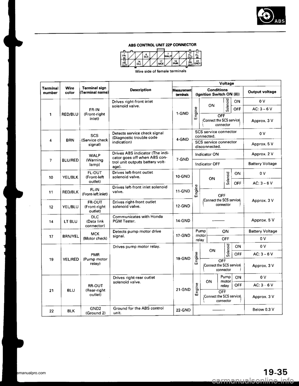
ABS CONTROL UNIT 22P CONNECIOR
Wire side ol lemale terminals
TerminalnumDerWirecolorTerminal 3i9nTerminal nameDescription
Voltage
Conditions(lgnition Switch ON (ll)lOutput voltagetominals
1RED/BLUFR-IN(Front-right
inlet)
Drives right-front inletsolenoid valve.
1-GND.9otur
ONIONOV
OFFAC:3-6V
OFF
lconnect the SCS servicel
connedor lApprox.3 V
BRN(Service checksignal)
Detects service check signal(Diagnostic trouble codeindication)4.GND
SCS service connectorconnected.OV
SCS service connectordisconnected.Approx. S V
7BLU/RED(Warning
ramp)
Drives ABS indicator {The indi-
cator goes off when ABS con-
trol unit outputs battery volt-age).
7.GND
lndicator ONApprox. 2 V
lndicator OFFBattery Voltage
10YEUBLKFL-OUT(Frontieft
outlet)
Drives left-front outletsolenoid valve.1O-GNDON
=
I
ONOV
OFFAC:3-6V
l'lRED/BLKFL-IN(Front-left inlet)
Drives left-front inlet solenoid11-GNDOFF
lconnect the SCS servicq connector lApprox.3 V
YEUBLUFR-OUT(Front-right
outlet)
Drives right-front outletsolenoid valve.12-GND
14LT BLU(Data linkconnectod
Communicates with HondaPGM Tester.14-GNDApprox. 5 V
17BRN/YELMCK(Motor check)
Detects PumP motor drivesignal.17-GNDPumpmotorrelay
ONBattery Vollage
OFFOV
19YEUREDPMR(Pump motorreray,
Drives pump motor relay.
19.GNDcl)
ON6IONOV
OFFAC:3-6V
OFFponnecl the SCS service]
connector IApprox.3 V
BLURR-OUT(Rear-right
outlet)
Drives right-rear outletsolenoid valve.
21.GND'a)
ONPumpmororrcray
ONOV
OFFAC:3 6V
OFF
lconnect the SCS service] connector lApprox.3 V
BLKGND2(Ground 2)Ground for the ABS controlunit.22.GNDBelow 0.3 V
19-35
www.emanualpro.com
Page 960 of 1395
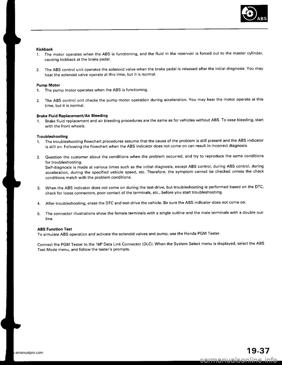
Kickback'1. The motor operates when the ABS is functioning. and the fluid in the reservoir is forced out to the master cylinder,
causing kickback at the brake pedal.
2. The ABS control unit operates the solenoid valve when the brake pedal is released after the initial diagnosis You may
hear the solenoid valve operate at this time, but it is normal
Pumo Motol
1. The pump motor operates when the ABS is functioning
2. The ABS control unit checks the pump motor operation during acceleration. You may hear the motor operate at this
time, but it is normal.
Brake Fluid Replacement/Ail Bleeding
L Brake fluid replacement and air bleeding procedures are the same as for vehicles without ABS To ease bleeding, start
with the front wheels.
Troubleshooting
1. The troubleshooting flowchart procedures assume that the cause of the problem is still present and the ABS indicator
is still on. Following the flowchart when the ABS indicator does not come on can result in incorrect diagnosis.
2. Ouestion the customer about the conditions when the problem occurred, and try to reproduce the same conditions
for troubleshooting.
Self-diagnosis is made at various times such as the initial diagnosis, except ABS control, during ABS control, during
acceleration, during the specified vehicle speed, etc. Therefore, the symptom canngt be checked unless the check
conditions match with the problem conditjons
3. When the ABS jndicator does not come on during the test-drive. but troubleshooting is performed based on the DTC,
check lor loose connectors, poor contact of the terminals, etc., before you start troubleshooting.
4. After troubleshooting, erase the DTC and test-drive the vehicle. Be sure the ABS indicator does not come on.
5. The connector illustratjons show the female terminals with a single outline and the male terminals with a double out-
l ne.
ABS Function Test
To simulate ABS operation and activate the solenoid valves and pump, use the Honda PGM Tester.
Connect the PGM Tester to the 16P Data Link Connector (DLC). When the System Select menu is displayed, select the ABS
Test Mode menu, and follow the tester's prompts.
19-37
www.emanualpro.com
Page 963 of 1395
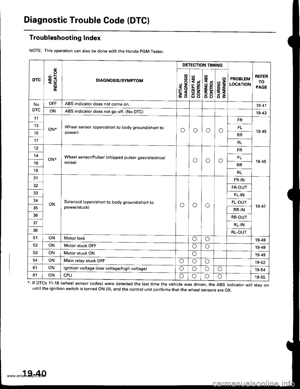
Diagnostic Trouble Code (DTC)
Troubleshooting Index
This operation can also be done with the Honda pGM Teste..
*: lf DTcs 11-18 {wheel sensor codes) were detected the last time the vehicle was driven, the ABs indicator wi
stav onuntil the ignition switch is turned ON (ll), and the control unit confirms that the wheel sensors are OK,
19-40
DTC3R
DETECTION TIMING
PROBLEM
LOCATION
REFER
TO
PAGE
Io
<=EXzd
8
93gl (J
4,,to
B8
2=
ET63
No
DTC
OFFABS indicator does not come on.19,4'l
ONABS indicator does not go off. (No DTC)19-43't1
oN*Wheel sensor {open/short to body ground/short topower)oooo
FR
19-45
13FL't5RR
17RL
12
oN*Wheel sensor/Pulser (chipped pulser gearlelectrical
notse,ooo
FR
19-45
't4FL
RR
18RL
31
ONSolenoid (open/short to body ground/short topower/stuck)ooo
FR-IN
19-47
32FR-OUT
FL.IN
34FL-OUT
RB-IN
36RR-OUT
37RL-IN
38RL.OUT
ONMotor lockoo19-49
ONMotor stuck OFFoo19-49
53ONMotor stuck ONo19-49
54ONMain relay stuck OFFoooia_at
6lONlgnition voltage (low voltage/high voltage)oooo'19-54
81ONoooo19-55
www.emanualpro.com