passenger HONDA CR-V 1997 RD1-RD3 / 1.G Owner's Manual
[x] Cancel search | Manufacturer: HONDA, Model Year: 1997, Model line: CR-V, Model: HONDA CR-V 1997 RD1-RD3 / 1.GPages: 1395, PDF Size: 35.62 MB
Page 980 of 1395
ABS Control Unit
Pulsers/Wheel
Sensors
Replacement
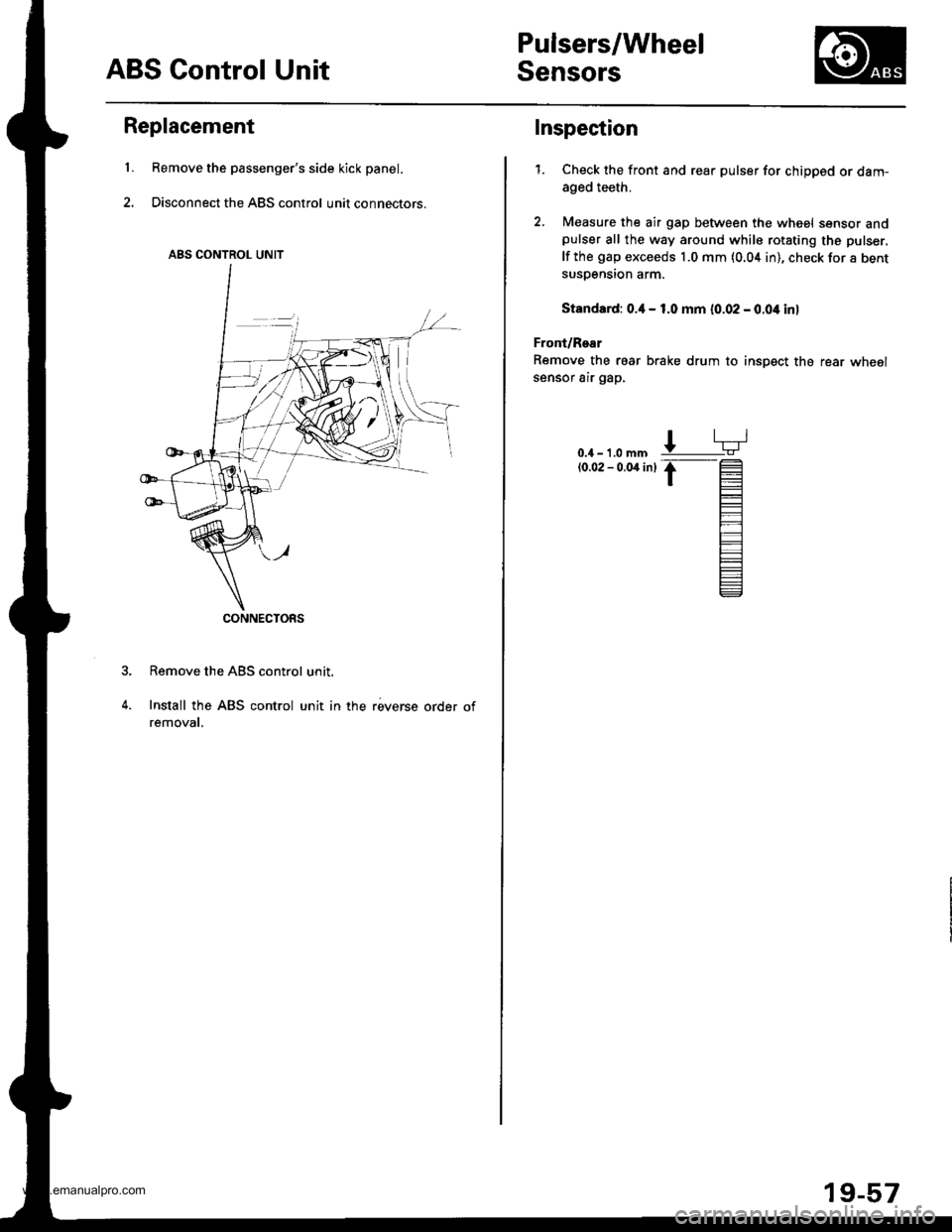
Remove the passenger's side kick panel.
Disconnect the ABS control unit connectors.
Remove the ABS control unit.
Install the ABS control unit in the reverse order ofremovat.
ABS CONTROL UNIT
CONNECTORS
L
Inspection
1.Check the front and rear pulser for chipped or dam-
aged teeth.
Measure the air gap between the wheel sensor andpulser all the way around while rotating the pulser.
lf the gap exceeds 1.0 mm (0.04 in), check for a bentsusDension arm.
Standard: o.il - 1.0 mm 10.02 - 0.04 inl
Front/Rear
Remove the rear brake drum to insDect the rear wheolsensor air gap,
0.4 - 1.0 mm(0.02 - 0.04 inl
19-57
www.emanualpro.com
Page 1025 of 1395
lnterior Trim
Headliner Removal and Installation
CAUTION: When prying with a tlat-tip screwdriver,
wrap it with protective tape to prevent damage.
NOTE:
. Take care not to bend and scratch the headliner.o Be careful not to damage the dashboard and other
interior trim.
1. Remove:
. Front and rear door side trim (see page 20-41). Front pillartrim (see page 20-41)
. Center pillar lower trim panel (see page 20-41). Center pillar upper trim (see page 20 41). Rear seat (one side, see page 20-63). Cargo area floor and cargo storage bin
{see page 20-43)
. Rear trim panel (see page 20-421
. Rear side trim panel (oneside, see page 20-42l,
. Rear hatch glass support strut (one side, seepage 20-78)
. Ouaner pillar trim panel {one side, see page 20-
42)
. Ceiling light, interior light and trunk light(see section 23)
. Rearview mirror (see page 20-28)
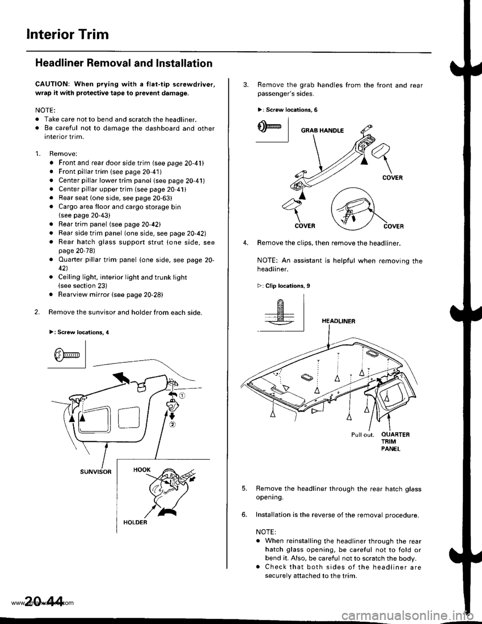
2. Remove the sunvisor and holder from each side.
>: Scaew location3, 4
I
A\"r- |Yr* || -
suNvtsoR
20-44
3. Remove the grab handles from
passenger's sides.
>r Screw locations, 6
the front and rear
ry_l
COVER
4. Remove the clips, then remove the headliner.
NOTE: An assistant is helpful when removing the
headliner.
>: Clip locations,9
HEADLINER
Pullout. OUARTERTRIMPANEL
5. Remove the headliner through the rear hatch glass
openrng.
6. Installation is the reverse of the removal procedure.
NOTE:
. When reinstalling the headliner through the rear
hatch glass opening, be careful not to fold or
bend it, Also, be careful not to scratch the body.. Check that both sides of the headliner are
securely attached to the trim.
www.emanualpro.com
Page 1033 of 1395
Dashboard
Side Air Vent Removal and
lnstallation
CAUTION:
. When prying with a flat-tip screwdriver, wrap it with
protec'tive tape, and apply protcctive tape around the
related parts to provent damage.
. Put on glov€s to protect your hands.
NOTE: Take care not to scratch the dashboard and related
parts.
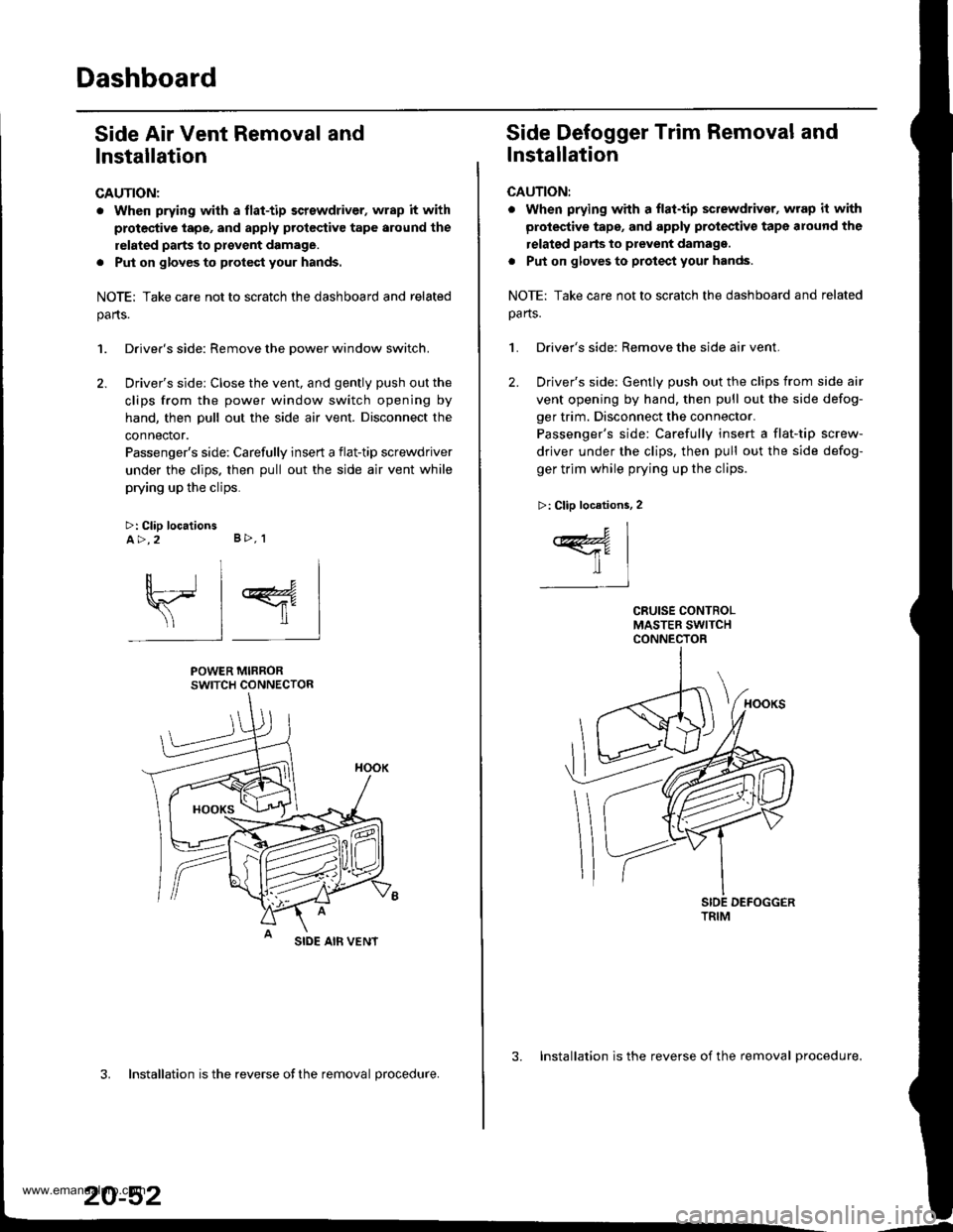
1. Driver's side: Remove the Dower window switch.
2. Driver's side: Close the vent, and gently push out the
clips from the power window switch opening by
hand, then pull out the side air vent. Disconnect the
connector.
Passenger's side: Carefully insert a flat-tip screwdriver
under the clips. then pull out the side air vent while
prying up the clips.
>: Clip locationsA>,2 B>, 1
sl 4
POWER MIRRORSWITCH CONNECTOR
SIDE AIB VENT
3. Installation is the reverse ofthe removal procedure.
20-52
3. Installation is the reverse of the removal procedure.
Side Defogger Trim Removal and
lnstallation
CAUTION:
. when prying whh a flat-tip sctewdriver, wrap it with
protective tape, and apply protectiv€ tape around the
relatgd parts to prevent damagg.
. Put on gloves to protect your hands.
NOTE: Take care not to scratch the dashboard and related
oa rts.
1. Driver's side: Remove the side air vent.
2. Driver's side: Gently push out the clips from side air
vent opening by hand, then pull out the side defog-
ger trim. Disconnect the connector.
Passenger's side: Carefully insert a flat-tip screw-
driver under the clips, then pull out the side defog-
ger trim while prying up the clips.
>: Clip locations, 2
c1
ffil-t
TRIM
www.emanualpro.com
Page 1034 of 1395
Dashboard Removal and Installation
SRS components are located in this area. Review the SRS
component locations, precautions, and procedures in the
SRS section {24) before preforming repairs or service.
CAUTION:
. When prying with a flat-tip screwdriver, wrap h withprotective tap€, and apply protective tape around the
related parts to prevgnt damage.
. Put on gloves to prot€ct your hands.
NOTE:
. An assistant is helpful when removing and installing
the dashboard.
. Take care not to scratch the dashboard, bodv and
other related parts.
1.Make sure you have the anti-theft code for the
radio, then write down the frequencies for the
radio's preset buttons.
Disconnect the negative battery cable. and wait at
least three minutes before beginning work.
Removei
a Driver's dashboard lower cover and knee bolster(see page 20-48)
. Glove box (see page 20-49)
. Lower console cover and center pocket (A/T
model, see page 20-49)
. Center console and center upper pocket (M/T
model, see page 20-47)
. Center dashboard lower cover (see page 20-50)
. Power window switch (see page 20-51)
. Driver's side air vent (see page 20-52)
. Driver's side defogger trim (see page 20-52)
Disconnect the driver's airbag connector, and lower
the steering column (see section 17)
NOTE: To prevent damage to the steering column,
wrap it with a shop towel.
2.
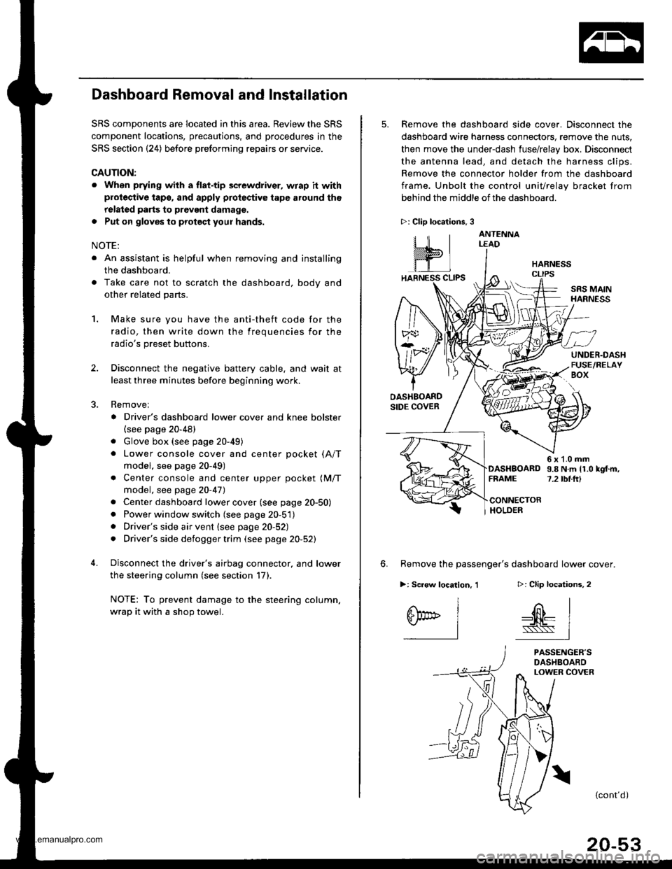
5. Remove the dashboard side cover. Disconnect the
dashboard wire harness connectors, remove the nuts,
then move the under-dash fuse/relay box. Disconnect
the antenna lead, and detach the harness clips.
Remove the connector holder from the dashboard
frame. Unbolt the control unit/relay bracket from
behind the middle of the dashboard.
HARNESS
6. Remove the passenger's dashboard lower cover.
D: Clip locations,
nl
-$t- Issj
I
ANTENNALEAD
>: Clip locations.
rttl
slllll
>: Scr€w location, 1
I
SF:oo I-l
SRS MAINHARNESS
UNDER.DASHFUSE/RELAYBOX
OASHBOARDSIDE COVER
6x1.0mm9.8Nm11.0kgf.m,7.2tbt.ftlDASHBOARDFFAME
CONNECTORHOLDER
PASSENGER'SDASHBOARDLOWER COVER
{cont'd)
www.emanualpro.com
Page 1036 of 1395
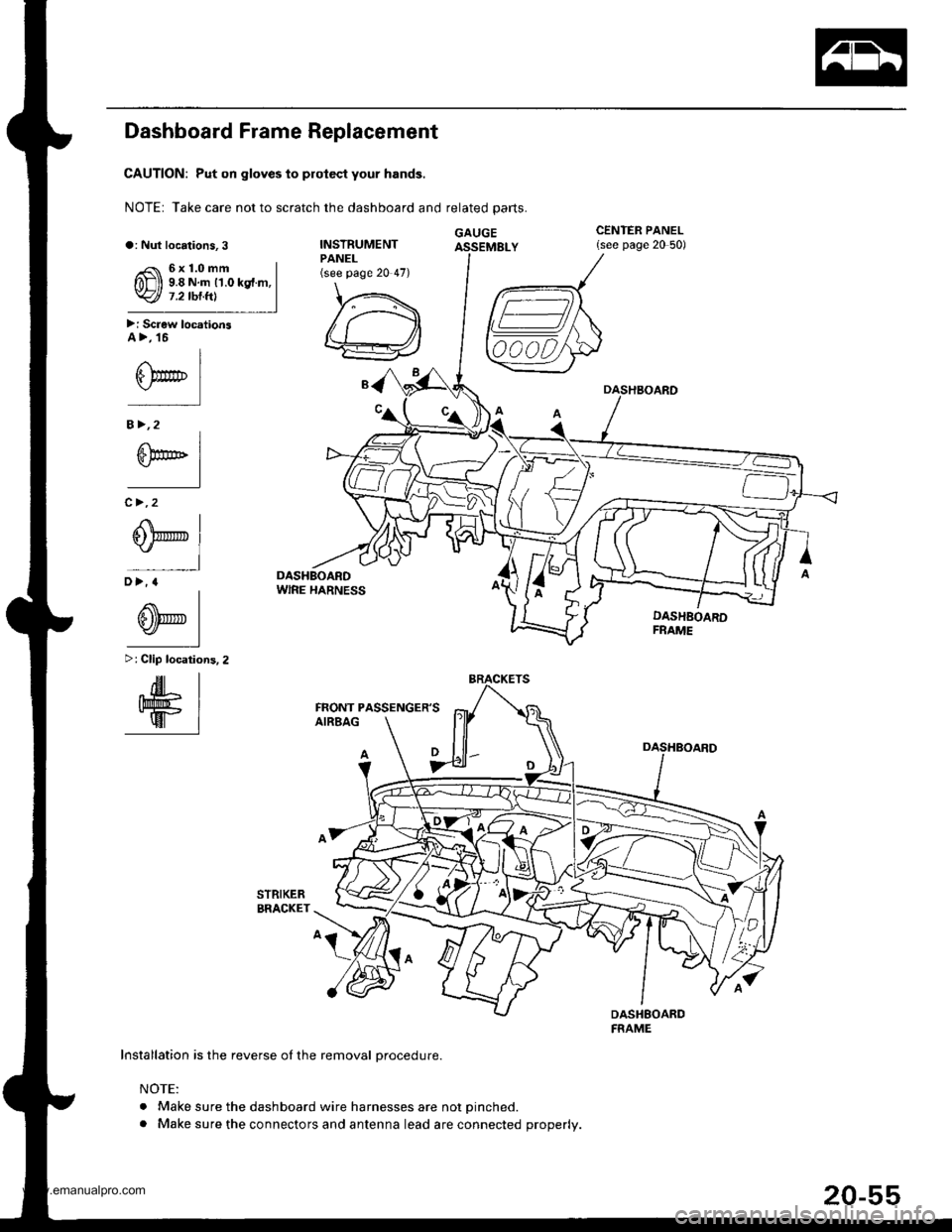
Dashboard Frame Replacement
CAUTION: Put on gloves to prolect your hands.
NOTE: Take care not to scratch the dashboard and related parts.
GAUGEa: Nut locations,3INSTRUMENTPANEL(see page 20 47)
\,.\
/ ,.-------f,\
lu /A
w
CENTER PANEL{see page 20 50)
6x1.0mm9.8 N.rn 11.0 kgf.m,7.2 tbt.ftl
>i Screw locationsA>,16
I
\,r*
B>,2
^l
S@t' 1-l
c >,2
I
0@l"l
D>.a
^l
0Fl-l
>: Clip localions.2
.dr IIhll'rifi- |-wr
i
DASHBOARDFRAME
DASHBOARDwlRE HARNESS
Installation is the reverse oI the removal orocedure.
NOTE:
. Make sure the dashboard wire harnesses are not Dinched.. Make sure the connectors and antenna lead are connected properly.
FRONT PASSENGER'S
www.emanualpro.com
Page 1040 of 1395
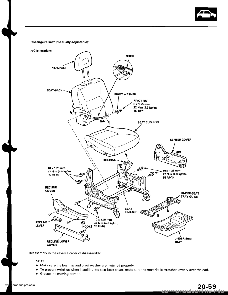
Passenger's seat (manually adiustablel:
>: Clip locations
HEADREST
SEAT.BACK
10 x 1.25 mm
PIVOT WASHER
PIVOT NUT8 x 1.25 mm22 N.m 12.2 kgl..n,16 tbt.ftl
SEAT CUSHION
CENTER COVER
BUSHING
COVER
Reassembly in the reverse order of disassembly.
NOTE:
. Make sure the bushing and pivot washer are installed properly.
. To prevent wrinkles when installing the seat-back cover, make sure the. Grease the moving portion.
'10 x 1.25 mm47 N.m {4.8 kgf m,
35 rbl.ft)
UNDER-SEATTRAY GUIDE
,U N.m 14.835 rbt.ft)
dHOOKS
10 x 1.25 mm17 N.m {4.8 kgl.m,35 tbf.ft)
HOOK
material is stretched evenly over the pad.
www.emanualpro.com
Page 1090 of 1395
a
Heater and Air Conditioning
Heater ...........21
NOTE: Section 21 ("Heater") is included in section 22.
Air Conditioning ......'..'.. '.'22'1
SUPPLEMENTAL RESTRAINT SYSTEM (SRS}
This model has an SRS which includes a driver's airbag in the steering wheel hub, a passenger's airbag in the dashboard
above the glove box ('97,00 models). and seat belt tensioners in the seat belt retractors ('98 - 00 models). Information
necessary to safely service the SRS is included in this Service Manual. ltems marked with an asterisk (*) on the contents
page include. or are located near, SRS components. Servicing, disassembling or replacing these items will require special
precautions and tools, and should only be done by an authorized Honda dealer.
@. To avoid rendering the SRS inoperative, which could lead to personal iniury or death in the event of 8 severe frontal
collision, all SRS service work must be performed by an authotized Honda dealer.
lmproper service procedures, including incorrect removal and installation of the SRS, could lead to personal iniury
caused by unintentional deployment of the airbags ('97 - 00 models), and seat belt tensioners 138 - 00 models).
Do not bump the SRS unit. Otherwise, the system may fail in case of a collision, or the airbags may deploy when the
ignition switch is ON {lll.
SRS eleqtrical wiring harnesses are identified by yellow color coding. Related components are located in the steering
column, front console, dashboard, dashboard lower panel, and in the dashboard above the glove box. Do not use elec-
tricaltest equipment on thes€ cilcuils.
www.emanualpro.com
Page 1097 of 1395
Description
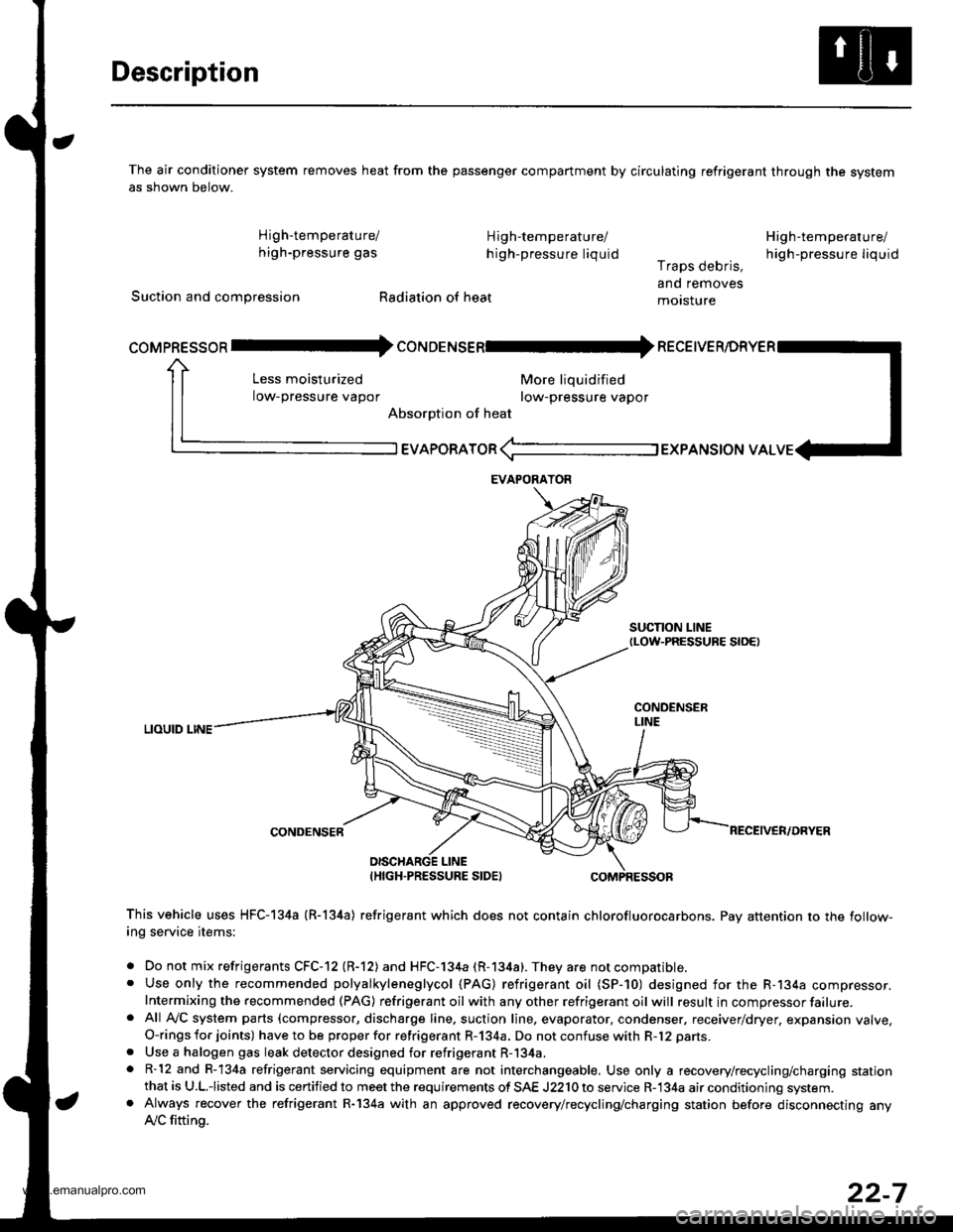
The air conditioner system removes heat from the passenger compartment by circulating refrigerant through the systemas shown below.
High'temperature/ High-temperature/
high-pressure gas h igh-pressure liquid
Suction and compression Radiation of heat
High-temperature/
high-pressu re liq uidr raps oeons,
and removes
motsture
More liquidified
row-pressure vapor
EVAPoRAToR (-l EXPANSToN vAL
SUCTION LINEtLow-PRESSURE S|OEt
LIOUID LINE
CONDENSER
coMpREssoR Il- coruoerusenl* necetve
Less moisturized
low-pressure vapor
Absorption of heat
DISCHARGE LINEIHIGH.PRESSURE SIDEI
This vehicle uses HFC-I34a (R-l34a) refrigerant which does not contain chlorofluorocarbons. Pay attention to the follow-ing service items:
. Do not mix refrigerants CFC-12 (R-12) and HFC-l34a (R-134a). They are not compatible.. Use only the recommended polyalkyleneglycol (PAG) refrigerant oil (SP-10) designed for the R-134a compressor.Intermixing the recommended (PAG) refrigerant oil with any other refrigerant oil will result in compressor failure.. Afl Ay'C system parts (compressor, discharge line. suction line, evaporator, condenser. receiver/dryer, expansion valve,O-rings for joints) have to be proper for refrigerant R-134a. Do not confuse with R-12 parts.
. Use a halogen gas leak detector designed for refrigerant R-134a.. R-12 and R-134a refrigerant servicing equipment are not interchangeable. Use only a recovery/recycling/charging stationthat is U.L.iisted and is certified to meet the requirements of SAE J2210 to service R-134a air conditioning system.. Always recover the refrigerant R-134a with an approved recovery/recycling/charging station before disconnecting anylVC fitting.
EVAPORAYOR
22-7
www.emanualpro.com
Page 1138 of 1395
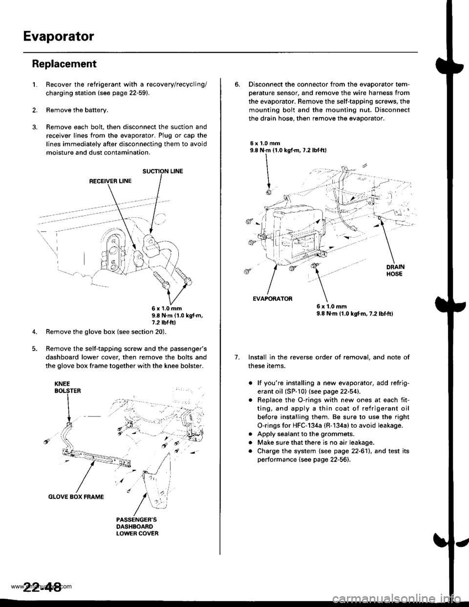
Evaporator
Replacement
1.Recover the refrigerant with a recovery/recycling/
charging station (see page 22-59).
Remove the battery.
Remove each bolt, then disconnect the suction and
receiver lines from the evaporator. Plug or cap the
lines immediately after disconnecting them to avoid
moisture and dust contamination,
RECEIVER LINE
..
\
6x1.0mm9.8 N'm (1.0 kgf m,7.2 tbl.ttl
Remove the glove box (see section 20).
Remove the self-tapping screw and the passenger's
dashboard lower cover, then remove the bolts and
the glove box frame together with the knee bolster.
GLOVE BOX FRAME
KNEE
22-44
6. Disconnect the connector from the evaoorator tem-
oerature sensor. and remove the wire harness from
the evaporator. Remove the self-tapping screws, the
mounting bolt and the mounting nut. Disconnect
the drain hose, then remove the evaporator.
5xl,0mm9.8 N.m {1.0
II
I
Io
kgf.m, 7.2 lbf.ftl
, -l: "
7.
EVAPORATOR
6x1.0mm9.8 N.m (1.0 kgtm,7.2lbf.ftl
Install in the reverse order of removal, and note of
these items.
. lf you're installing a new evaporator, add refrig-
erant oil (SP.10) (see page 22-541.
Replace the O-rings with new ones at each fit-
ting, and apply a thin coat of refrigerant oil
before installing them. Be su.e to use the right
O-rings for HFC-134a (R-134alto avoid leakage.
Apply sealant to the grommets.
Make sure that there is no air Ieakage.
Charge the system (see page 22-6'll, and test its
performance (see page 22-56]-,
a
a
a
www.emanualpro.com
Page 1146 of 1395
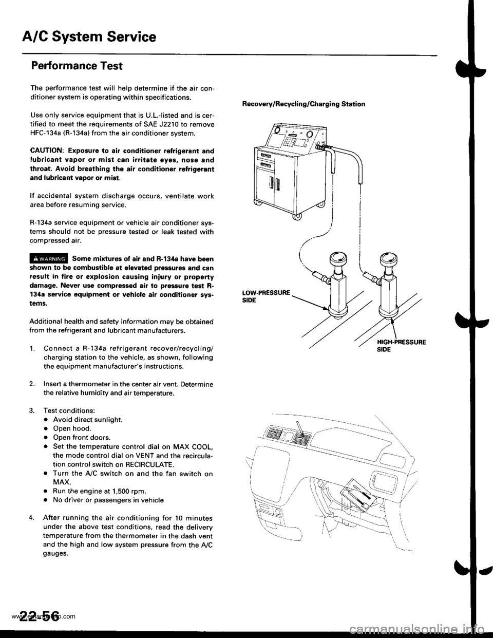
A/G System Service
Performance Test
The performance test will helD determine if the air con-
ditioner system is operating within specifications.
Use only service equipment that is U.L.-listed and is cer-
tified to meet the requirements of SAE J2210 to remove
HFC-134a (R-134a) from the air conditioner svstem.
CAUTION: Exposure to air condiiioner r€trigerant and
lubricant vapor or mist can irritate €yes, nose and
throat. Avoid bre8thing the air conditioner retrige.ant
and lubricant vapor or mist,
lf accidental system discharge occurs. ventilate work
area before resuming service.
R-134a service equipment o. vehicle air conditioner sys-
tems should not be pressure tested or leak tested with
comDressed air.
@ some mixtur€s ol air and R-134a have becn
shown to be combuslible at olsvated pressures and can
result in lire or explosion causing iniury or property
damage. Never use compressed air to prgssure test R-
13i[a service equipment or vehicle air conditioner sys.
tems.
Additional health and safety information may be obtained
from the refrigerant and lubricant manufacturers.
Recovory/Recycling/charging station
LOW.PRESSURESIDE
1.Connect a R-134a refrigerant recover/recycling/
charging station to the vehicle, as shown. following
the equipment manufacturer's instructions,
Insen a thermometer in the center air vent. Determine
the relative humidity and air temperature.
Test conditions:
. Avoid direct sunlight.
o Open hood.
. open front doors.
. Set the temperature control dial on MAX COOL,
the mode control dial on VENT and the reci.cula-
tion control switch on RECIRCULATE.
. Turn the A,/C switch on and the fan switch on
MAX.
. Run the engine at 1,500 rpm.
. No driver or passengers in vehicle
After running the air conditioning for 10 minutes
under the above test conditions, read the deliverv
temperature from the thermometer in the dash vent
and the high and low system pressure from the Ay'Cgauges.
2.
22-56
www.emanualpro.com