step HONDA CR-V 1997 RD1-RD3 / 1.G Owner's Manual
[x] Cancel search | Manufacturer: HONDA, Model Year: 1997, Model line: CR-V, Model: HONDA CR-V 1997 RD1-RD3 / 1.GPages: 1395, PDF Size: 35.62 MB
Page 438 of 1395
Release Bearing
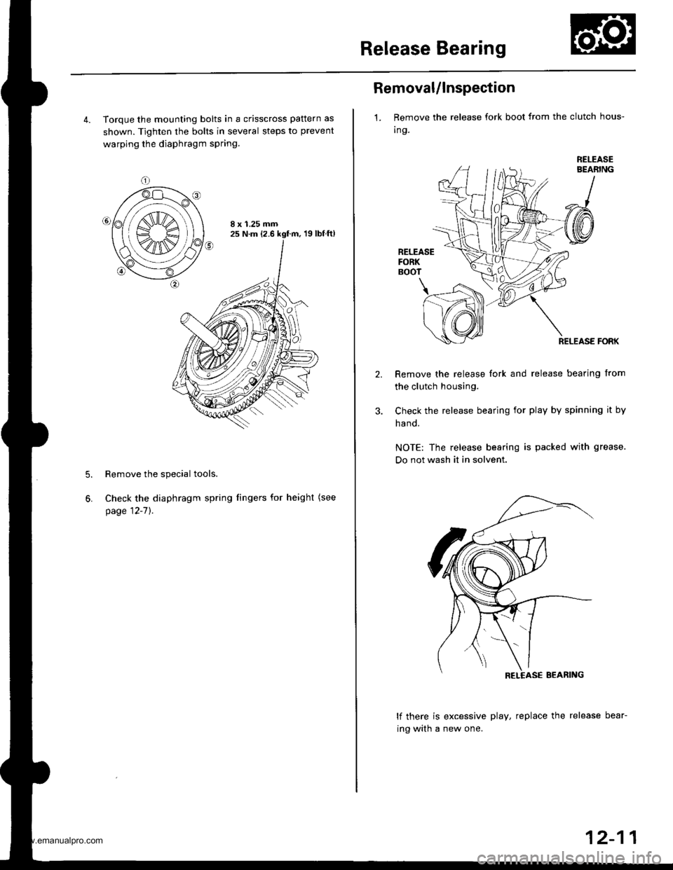
4. Torque the mounting bolts in a crisscross pattern as
shown. Tighten the bolts in several steps to prevent
warping the diaphragm spring.
8 x 1.25 mm25 N.m (2.6 kgf.m, 19lbfft)
Remove the special tools.
Check the diaphragm spring fingers for height (see
page 12-7]'.
5.
6.
Removal/lnspection
1. Remove the release fork boot from the clutch hous-
Ing.
RELEASEBEABING
RELEASEFORKBOOT
\
RELEASE FORK
Remove the release fork and release bearing from
the clutch housing.
Check the release bearing for play by spinning it by
ha nd.
NOTE: The release bearing is packed with grease.
Do not wash it in solvent.
lf there is excessive play, replace the release bear-
ing with a new one.
12-11
www.emanualpro.com
Page 454 of 1395
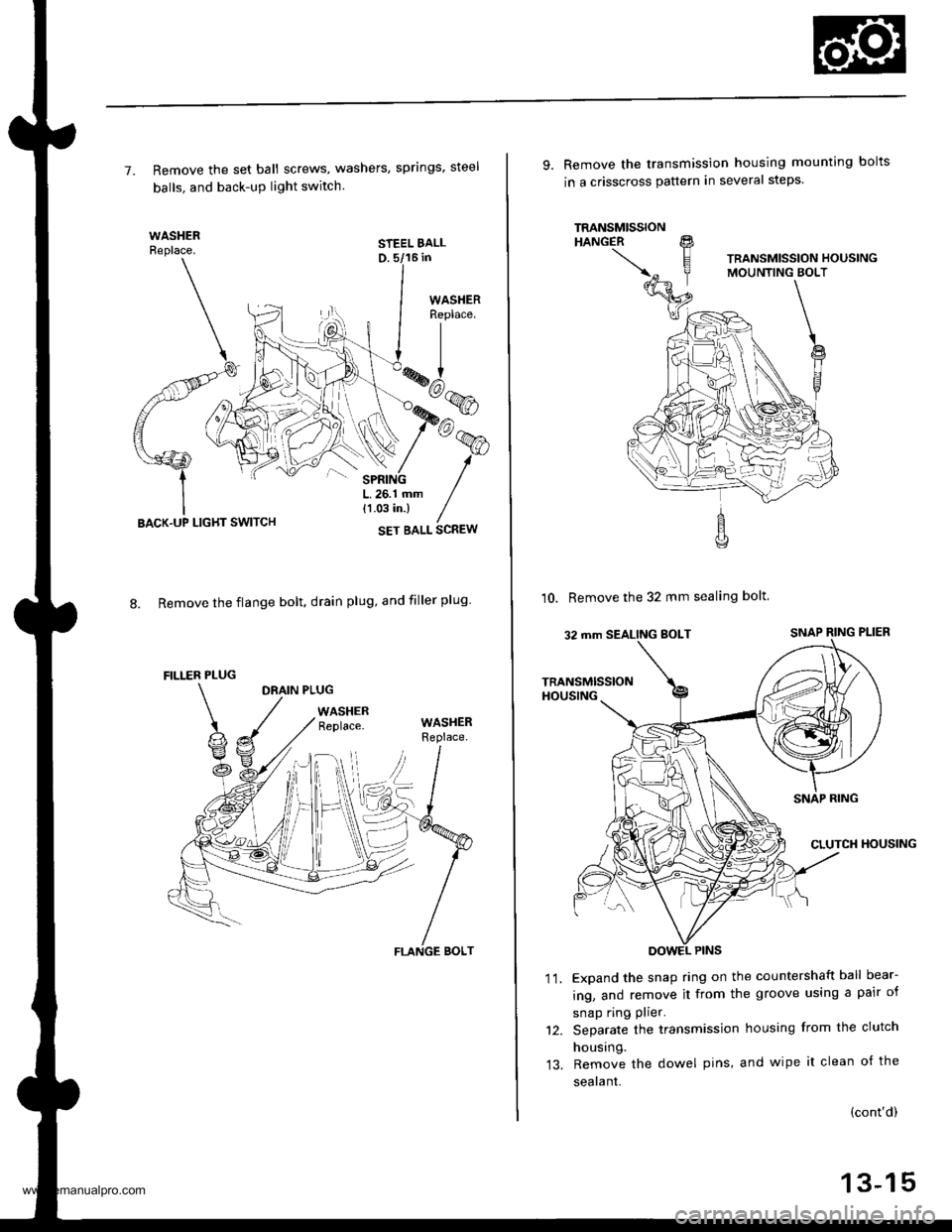
7. Remove the set ball screws, washers, springs, steel
balls. and back-uP light switch.
STEEL BALLD. 5/16 in
8. Remove the flange bolt. drain plug, and filler plug
DRAIN PLUG
WASHERReplace.
LIGHT SWITCH
FILLER PLUG
WASHERReplace.
FLANGE BOLT
9. Remove the transmission housing mounting bolts
in a crisscross pauern in several steps.
10. Remove the 32 mm sealing bolt
Expand the snap ring on the countershaft ball bear-
ing, and remove it from the groove using a pair of
snap ring plier.
Separate the transmission housing from the clutch
housing.
Remove the dowel pins, and wipe it clean of the
sealant.
'I t.
(cont'd)
13-15
www.emanualpro.com
Page 478 of 1395
Final Driven Gear RePlacement
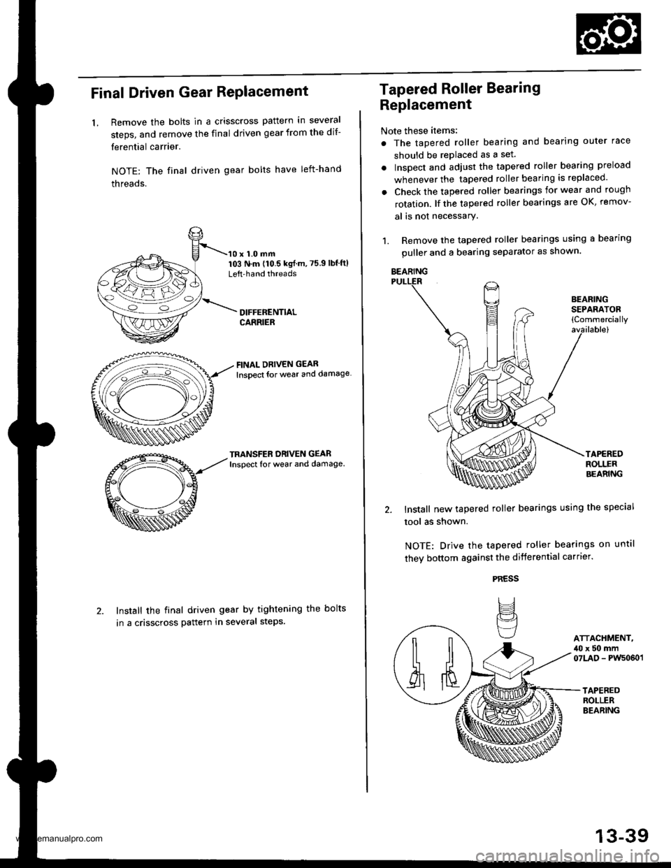
LRemove the bolts in a crisscross pattern in several
steps, and remove the final driven gear from the dif-
ferential carrier.
NOTE: The final driven gear bolts have left-hand
threads.
10 x 1.0 mm103 N.m (10.5 kgf m,75.9lbf'ftlLeft'hand threads
FINAL DRIVEN GEAR
lnsoect {or weal and damage
TRANSFER ORIVEN GEARInspect for wear and damage.
Install the final driven gear by tightening the bolts
in a crisscross pattern in several steps.
Tapered Roller Bearing
Replacement
Note these items:
. The tapered roller bearing and bearing outer race
should be replaced as a set.
. Inspect and adiust the tapered roller bearing preload
whenever the tapered roller bearing is replaced'
. Check the tapered roller bearings for wear and rough
rotation. lf the tapered roller bearings are OK, remov-
al is not necessary.
1. Remove the tapered roller bearings using a bearing
puller and a bearing separator as shown.
Install new tapered roller bearings using the special
tool as shown.
NOTE: Drive the tapered roller bearings on until
they bottom against the differential carrter.
PRESS
IJ
BEARINGSEPAFATOB{Commercially
ATTACHMENT,,10 x 50 mm07LAD - PWs060 l
BEARING
13-39
www.emanualpro.com
Page 492 of 1395
Transter Gear Backlash Inspection and Transfer Gear
Tooth Contaqt Inspection
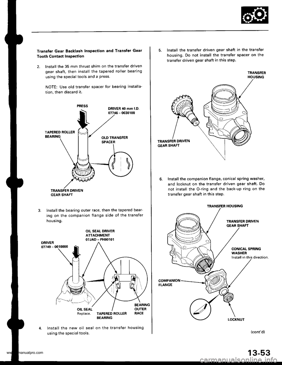
2. lnstall the 35 mm thrust shim on the transfer driven
gear shaft, then install the tapered roller bearing
using the special tools and a press.
NOTE: Use old lransfer spacer for bearing installa-
tion, then discard it.
TRANSFER DRIVENG€AR SHAFT
Install the bearing outer race, then the tapered bear-
ing on the companion flange side ot the transfer
housing.
3.
OIL SEAL DRIVERATTACHMENT07JAD - PH80101DRIVER077/tg - 001qt00
Replace.TAPERED ROLLERBEARING
Install the new oil seal on the transfer housing
using the special tools.
5. Install the transfer driven gear shaft in the transfer
housing. Do not install the transfer spacer on the
transfer driven gear shaft in this step.
TRANSFERHOUSING
Installthe companion flange. conical spring washer,
and locknut on the transfer driven gear shaft. Do
not install the O-ring and the back-up ring on the
transfer gear shaft in this step.
6,
COMPANIONFLANGE
CONICAL SPRING
direction.
(cont'd)
13-53
TRANSFER HOUSING
WASHER
www.emanualpro.com
Page 493 of 1395
Transfer Assembly
Reassembly (cont'd)
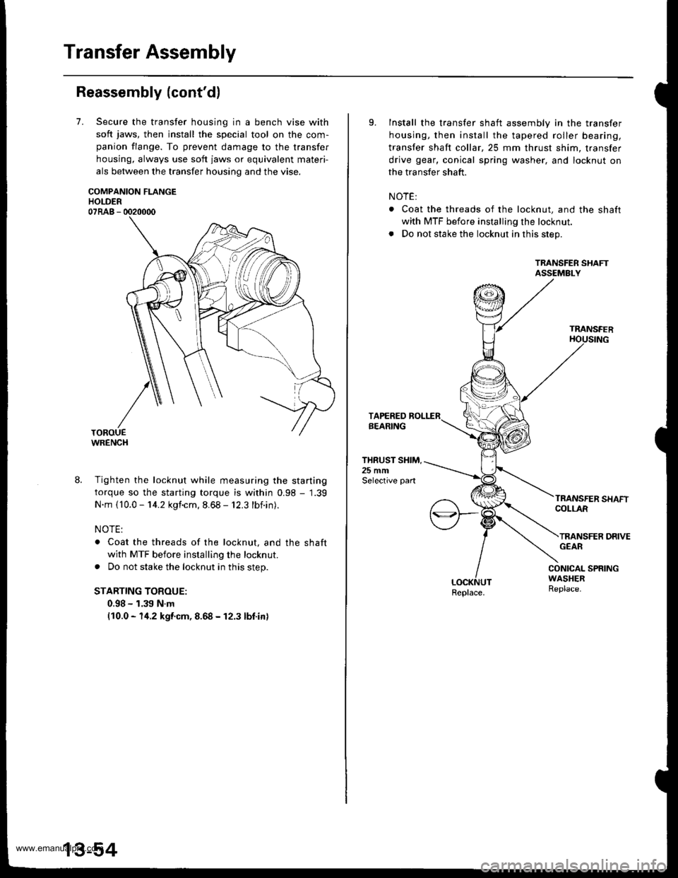
7.Secure the transfer housing in a bench vise with
soft jaws, then install the special tool on the com-
panion flange. To prevent damage to the transfer
housing, always use soft jaws or equivalent materi-
als between the transfer housing and the vise.
COMPANION FLANGEHOLDER07RAB - 0020000
WRENCH
8. Tighten the locknut while measuring the starting
torque so the starting torque is within 0.98 - 1.39
N.m {10.0 - 14.2 kgf.cm. 8.68 - 12.3 lbf.in).
NOTE:
. Coat the threads of the locknut, and the shaft
with MTF before installing the locknut.
. Do not stake the locknut in this step.
STARTING TOROUE:
0.98 - 1.39 N.m(10.0 - 14.2 kgf.cm, 8.68 - 12.3 lbf.in)
9.Install the transfer shaft assembly in the transfer
housing, then install the tapered roller bearing,
transfer shaft collar,25 mm thrust shim, transfer
drive gear, conical spring washer, and locknut on
the transfer shaft.
NOTE:
. Coat the threads of the locknut, and the shaft
with MTF before installing the locknut.
. Do not stake the locknut in this step.
TRANSFER SHAFTASSEMBLY
TRANSFER
THRUST SHIM.25 mmSelective part
COLLAR
TRANSFER DRIVEGEAR
CONICAL SPRINGWASHERReplace.Replace.
www.emanualpro.com
Page 494 of 1395
TOROUE WRENCH
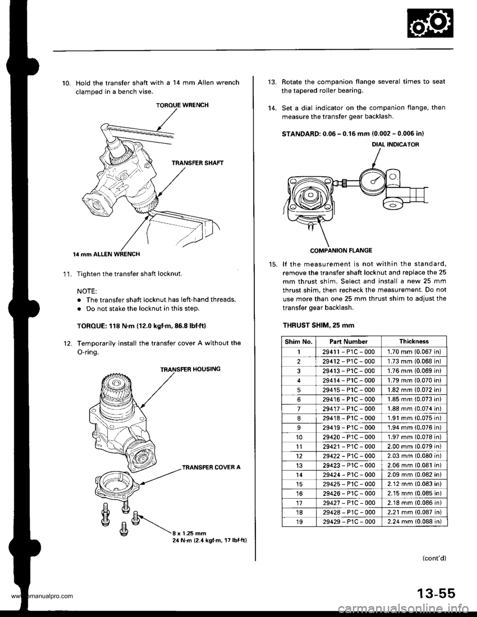
10. Hold the transfer shaft with a 14 mm Allen wrench
clamped in a bench vise.
lil mm ALLEN WRENCH
Tighten the transfer shaft locknut.
NOTE:
. The transfer shaft locknut has left-hand threads,
. Do not stake the locknut in this step.
TOROUE: 118 N.m (12.0 kgf.m,86.8 lbf.ft)
Temporarily install the transfer cover A without the
O-ring.
11.
rl0ustNG
TRANSFER COVER A
8xL25mm24 N.m (2.4 kgt.m. 17 lbnftl
'14.
Rotate the companion flange several times to seat
the tapered roller bearing.
Set a dial indicator on the companion flange, then
measure the transfer gear backlash.
STANDARD: 0.06 - 0.15 mm 10.002 - 0.006 in)
COMPANION FLANGE
lf the measurement is not within the standard,
remove the transfer shaft locknut and replace the 25
mm thrust shim. Select and install a new 25 mm
thrust shim. then recheck the measurement. Do not
use more than one 25 mm thrust shim to adjust the
transfer gear backlash,
THRUST SHlM,25 mm
DIAL INDICATOR
Shim No.Part NumbelThickness
I2941r - P1C - 0001.70 mm 10.067 in
229412-PlC-000'L73 mm (0.068 in
329413-P1C-0001.76 mm (0.069 in
29414-PlC-0001.79 mm (0.070 in
529415-P1C-0001.82 mm (0.072 in
629416-PlC-0001.85 mm (0.073 in
7294'�17-PrC-0001.88 mm (0.074 in
8294'18-P1C-0001.91 mm (0.075 in)
29419-PlC-0001.94 mm (0.076 in)'1029420-P1C-0001.97 mm 10.078 in)
1129421 - P1C - 0002.00 mm (0.079 in)
1229422 -P1C - 0002.03 mm (0.080 in)
1329423-P1C-0002.06 mm (0.081 in)
l429424-P1C-0002.09 mm (0.082 in)
29425-P'tC-0002.12 mm (0.083 in)
1629426-P1C-0002.15 mm (0.085 in)
1729427 -P1C-0002.18 mm {0.086 in)'1829428-P1C-0002.21 mm {0.087 in)
1929429-P1C-0002.24 mm 10.088 in)
(cont'd)
13-55
www.emanualpro.com
Page 498 of 1395
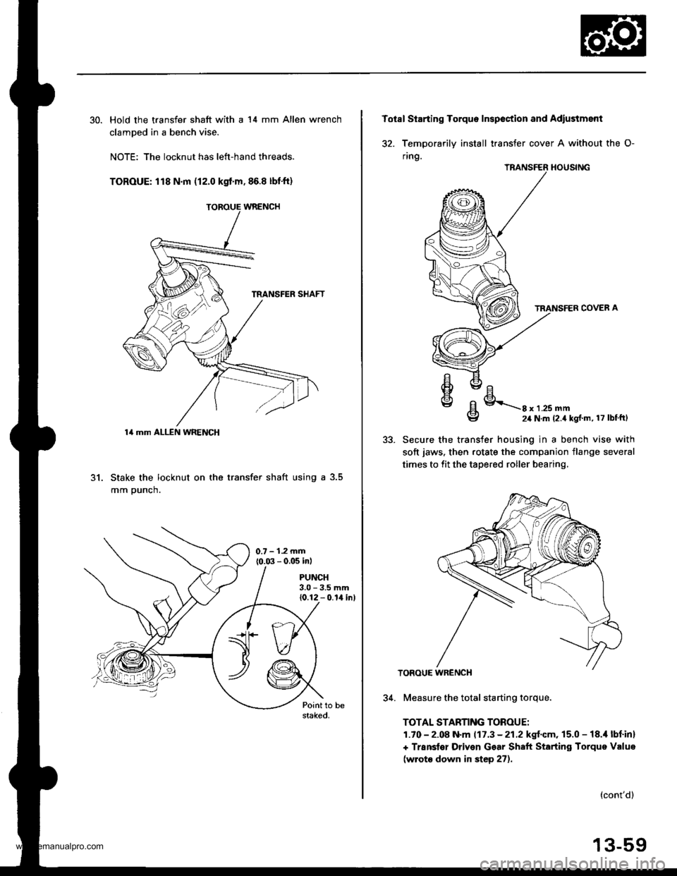
30. Hold the transfer shaft with a 14 mm Allen wrench
clamDed in a bench vise.
NOTE: The locknut has left-hand threads.
TOROUE: 118 N.m (12.0 kgt'm,86.8 lbf'ft)
31. Stake the locknut on the transfer shaft using a 3.5
mm Dunch.
PUNCH3.0 - 3.5 mm{0.12 - 0.14 inl
14 mm ALLEN WRENCH
Totsl Starting Torquo Inspoction and Adiustment
32. Temoorarilv install transfer cover A without the O-
ring.
TRANSFER HOUSING
TRANSFER COVER A
oEl
€lE/Ehvc/E\\g8 x 1 .25 mm24 N.m (2.4 kg{ m, 17 lbtftl
5t.Secure the transfer housing in a bench vise with
soft jaws. then rotate the companion flange several
times to fit the tapered roller bearing,
TOROUE WR€NCH
34. Measure the total starting torque.
TOTAL STARNNG TOROUE:
1.70 - 2.08 N.m 117.3 - 21.2 kgf.cm, 15.0 - 18.i1 lbf inl
+ Transter Driven Gear Shaft Starting Torque Value
(wrot€ down in step 27).
(cont'd)
13-59
www.emanualpro.com
Page 499 of 1395
Transfer Assembly
Reassembly (cont'd)
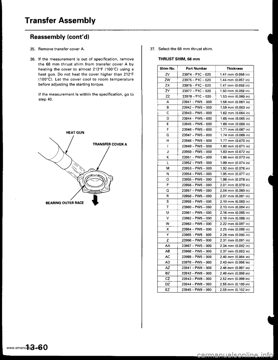
Remove transfer cover A.
lf the measurement is out of specification, remove
the 68 mm thrust shim from transfer cover A by
heating the cover to almost 212'F (100'C) using a
heat gun. Do not heat the cover higher than 212F
(100"C). Let the cover cool to room temperature
before adjusting the starting torque.
lI the measurement is within the specification, go to
step 40.
COVER A
BEARING OUTER RACE
35.
36.
HEAT GUN
13-60
37. Select the 68 mm thrust shim.
THRUST SHIM, 68 mm
Shim No.Part NumberThickne3s
zv23914-P1C-0201.41 mm (0.056 in)
zw23975-P1C-020'1.44 mm 10.057 in)
zx23916 PlC -020'1.47 mm (0.058 in)
ZI23917 -P1C-O201.50 mm (0.059 in)
zz23978-PlC-0201.53 mm (0.060 in)
23941 - PW5 0001.56 mm {0.061 in)
23942-PWs-0001.59 mm (0.063 in)
c23943-PW5-000't.62 mm (0.064 in)
D23944 PW5 - 0001.65 mm (0.065 in)
E23945-PWs-0001.68 mm (0.066 in)
F23946-PW5-0001.71 mm 10.067 in)
G23947-PW5-000'1.74 mm 10.069 in)
23948-PWs-0001.77 mm (0.070 in)
23949-PWs-0001.80 mm (0.071 in)
239s0-PW5-0001.83 mm (0.072 in)
K23951 - PW5 - 0001.86 mm (0.073 in)
L23952-PWs-0001.89 mm {0.074 in)
239s3-PWs-0001.92 mm {0.076 ini
N23954-PW5-0001.95 mm (0.077 in)
o23955-PW5-0001.98 mm (0.078 in)
P23956 - PW5 , 0002.01 mm (0.079 in)
o23957-PWs-0002.04 mm (0.080 in)
R23958-PWs-0002.07 mm (0.081 in)
23959-PW5-0002.10 mm (0.083 in)
T23960-PW5-0002.13 mm (0.084 in)
U23961 - PW5 - 0002.16 mm (0.085 in)
23962-PW5-0002.19 mm (0.086n)
23963-PWs-0002.22 mm (0.087n)
X23964-PWs-0002.25 mm (0.089n)
23965,PWs-0002.28 mm 10.090n)
23966-PW5-0002.31 mm {0.091 in)
23967-PWs-0002.34 mm (0.092 in)
AB23968-PWs-0002.37 mm (0.093 in)
AC23969-PWs-0002.40 mm {0.094 in}
AD23970-PW5-0002.43 mm (0.096 in)
M23941 - PW8 - 0002.46 mm {0.097 'n}
BZ23942-PW8-0002.49 mm (0.098 in)
cz23943-PW8-0002.52 mm {0.099 ini
DZ23944-PW8-0002.55 mm (0.100 in)
EZ23945-PW8-0002.58 mm (0.102 ini
www.emanualpro.com
Page 503 of 1395
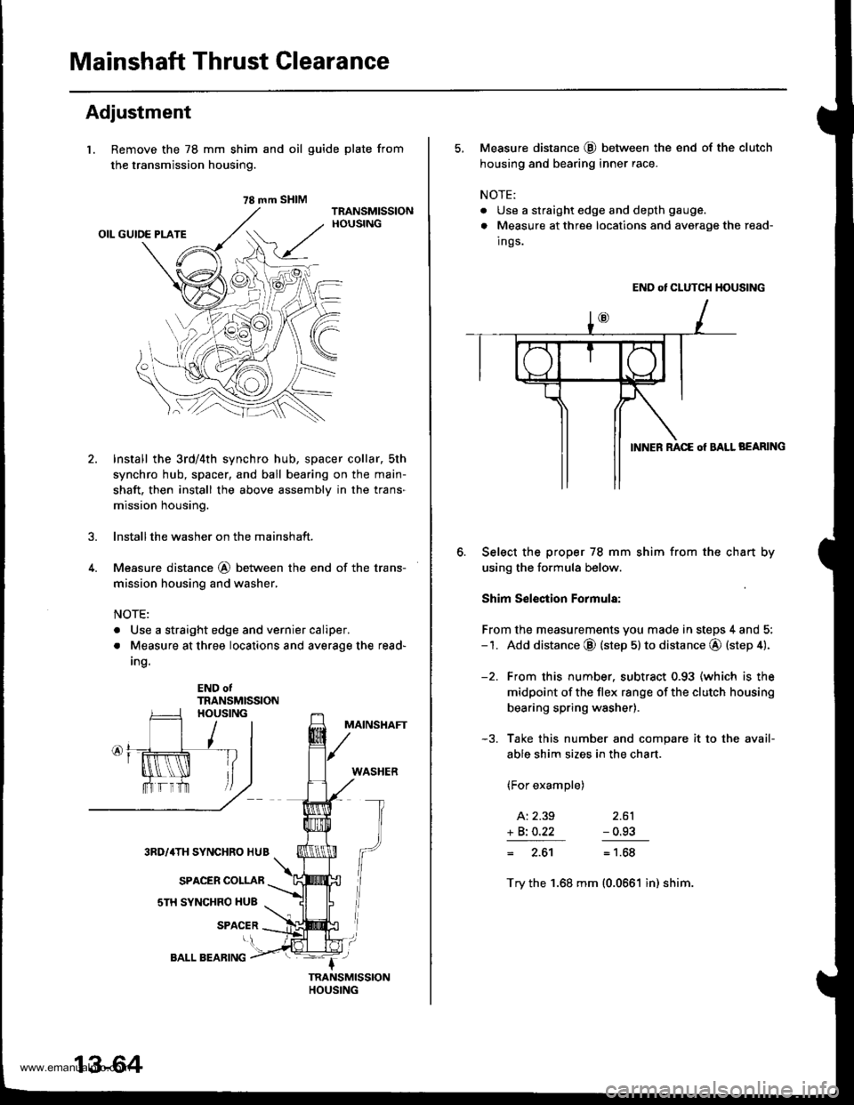
Mainshaft Thrust Clearance
Adjustment
l. Remove the 78 mm shim
the transmission housing.
4.
and oil guide plate from
Install the 3rd/4th synchro hub, spacer collar, sth
synchro hub, spacer, and ball bearing on the main-
shaft. then install the above assembly in the trans-
mission housing.
lnstallthe washer on the mainshaft.
Measure distance @ between the end of the trans-
mission housing and washer,
NOTE:
. Use a straight edge and vernier caliper.
. Measure at three locations and average the read-
Ing.
END otTRANSMISSION
MAINSHAFT
WASHER
3RD/4TH SYNCHRO HUB
SPACER COLLAR
sTH SYNCHRO HUB
SPACER
78 mm SHIM
13-64
BALL BEARING
5, Measure distance @ between the end of the clutch
housing and bearing inner race.
NOTE:
. Use a straight edge and depth gauge.
. Measure at three locations and avorage the read-
Ings.
END ot CLUTCH HOUSING
BEARING
Select the proper 78 mm shim from the chan by
using the formula below.
Shim S€lection Formula:
From the measurements you made in steps 4 and 5:-1. Add distance @ (step 5) to distance @ (step 4).
-2. From this number. subtract 0.93 (which is the
midpoint of the flex range of the clutch housing
bearing spring washer).
-3. Take this number and compare it to the avail-
able shim sizes in the chart.
(For example)
A: 2.39 2.61
+ Bi O.22 - 0.93
= 2.61= 1.68
Try the 1.68 mm (0.0661 in) shim.
www.emanualpro.com
Page 509 of 1395
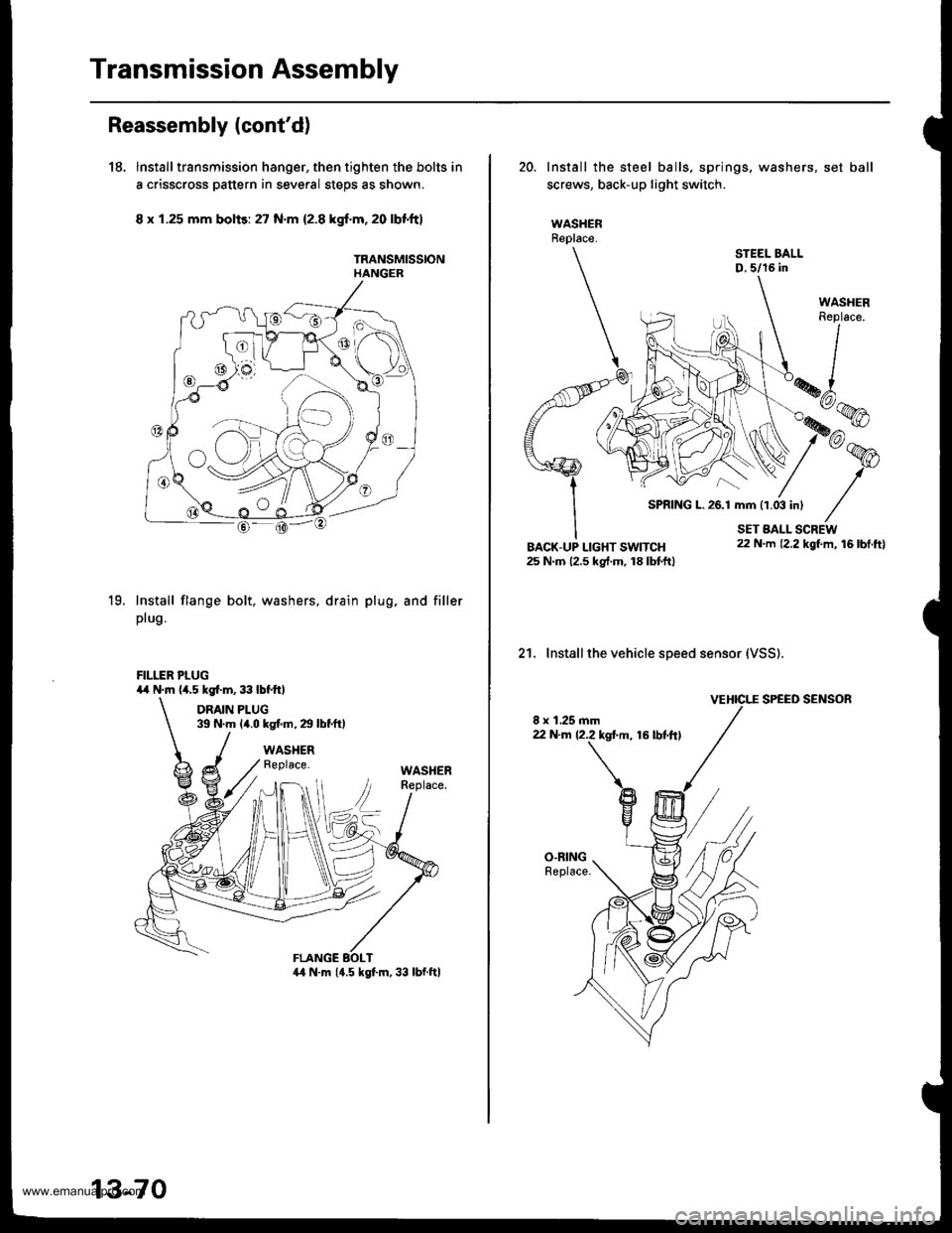
Transmission Assembly
Reassembly lcont'd)
18. Installtransmission hanger, then tighten the bolts in
a crisscross pattern in several steps as shown.
8 x 1.25 mm bolis: 27 N.m 12.8 kgf.m,20 lbf'ft}
TRANSMISSIONHANGER
19.Install flange bolt,
plug.
washers, drain plug. and filler
FILLER PLUG4,r N.m (a.5 kgl.m,33lbtftl
DRAIN PLUG39 N.m {4.0 kg{.m,29lbtftl
WASHERReplace.WASHER
13-70
20. Install the steel balls, springs. washers, set ball
screws, back-up light switch.
WASHERReplace.
STEEL BALLD,5/16 in
21. Installthe vehicle speed sensor (VSS).
VEHICI."E SPEED SENSOR
8 x 1.25 mm22 N.m 12.2 kgl.m, 16 lbt.ftl
SPRING L.26.1 mm 11.03 inl
www.emanualpro.com