HONDA CR-V 1997 RD1-RD3 / 1.G Workshop Manual
CR-V 1997 RD1-RD3 / 1.G
HONDA
HONDA
https://www.carmanualsonline.info/img/13/5778/w960_5778-0.png
HONDA CR-V 1997 RD1-RD3 / 1.G Workshop Manual
Page 1244 of 1395
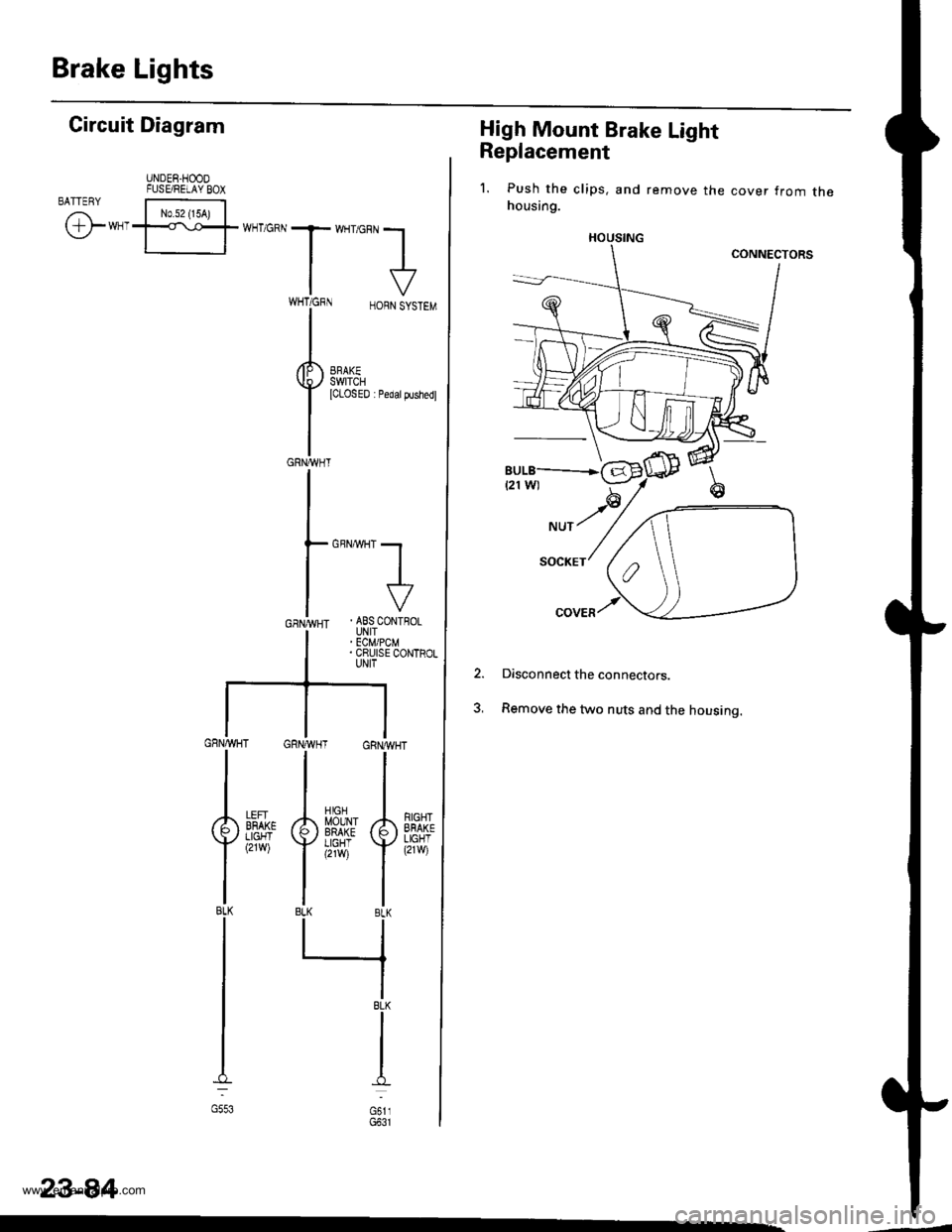
Brake Lights
High Mount Brake Light
Replacement
1. Push the clips, and remove the cover from thehousing.
Disconnect the connectors.
Remove the two nuts and the housing.
2.
HOUSING
Gircuit Diagram
UNDER.HOODFUSE/RELAY BOXBATTENY
/,i | No.s2 {15A) |
\Y*-I=f*-'o*T*'no"l
IV
T:,^-,
HORNSYSTEM
I
i.t53l| *",*"",
GRNA,VHT
GBNMHT -.1
I
I
. ABS CONTFOLUNIT' ECM/PCM. CRUISE CONTROLUNIT
GRNAVHT GRNWH
ll
tl
A[$^Jlr A
Yi,?'il Y
tlBLK BLK
llrl
IBLK
I
I
d
oi,,
RIGHTEFAKELIGHT(21w)
LEFIBFAKELIGHT(2rw)
BLK
G553
23-84
www.emanualpro.com
Page 1245 of 1395
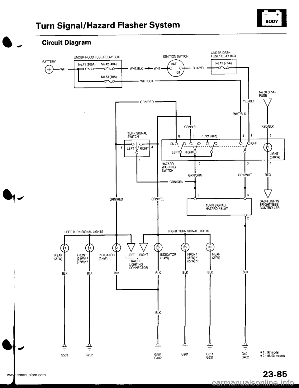
Turn SignallHazard Flasher System
UNDEF HOOD FUSE/NELAY BOX
N0.30 (7.54)FUSE
V
IREO/BLK
l,
t'IFqD
.+
DASH LIGHTSBSIGHTNESSCONTROLLER
HAZARDWARNINGswtTcH
_ GRN/ORN
YEUBLK
WHTiELK
GRNAVHT
O -. Circuit Diagram
BATTEFY
@**'
q-
103
GRN/ORN
INDICATOR
TFAILERLIGHTINGCONNECTOR
INDICATOR(1.4W)
BLK
G553
IGN T]ON SWITCHUNDER.OASHFUSE/RELAY BOX
No 12 (7.sA)
l----r-l-----i-F-- --------_ \
BtK
G401G402
:i1r'97model*2 :'98-00 models
23-85
www.emanualpro.com
Page 1249 of 1395
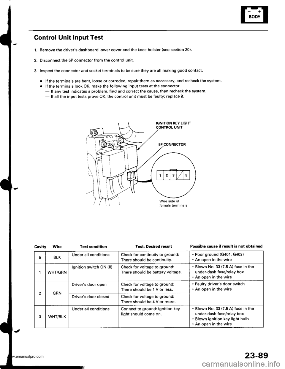
Control Unit Input Test
l. Bemove the driver's dashboard lower cover and the knee bolster (see section 20).
2, Disconnect the 5P connector from the control unit.
3. Inspect the connector and socket terminals to be sure they are all making good contact.
. lf the terminals are bent, loose orcorroded, repairthem as necessary, and recheck the system.
. lf the terminals look OK, make the following input tests at the connector.- lf any test indicates a problem, find and correct the cause. then recheck the system.
- lf all the input tests prove OK, the control unit must be faulty; replace it.
IGNITION KEY LIGHTCONTROL UNIT
5P CONNECTOR
\
))
Test conditionCavityWireTest: Desired resultPossible cause if r€sult is not obtained
BLKUnder all conditionsCheck for continuity to ground:
There should be continuity.
. Poor ground {G401, G402}. An open in the wire
'IWHT/GRN
lgnition switch ON (ll)Check for voltage to ground:
There should be battery voltage.
. Blown No. 33 (7.5 A) fuse in the
under-dash fuse/relay box. An open in the wire
GRN
Driver's door openCheck for voltage to ground:
There should be 1 V or less.
. Faulty driver's door switch. An open in the wire
Driver's door closedCheck for voltage to ground:
There should be 4 V or more.
WHT/BLK
Under all conditionsConnect to ground: lgnition key
light should come on.
Blown No. 33 (7.5 A) fuse in the
under-dash fuse/relay box
Blown ignition key light bulb
An open in the wire
23-89
www.emanualpro.com
Page 1250 of 1395
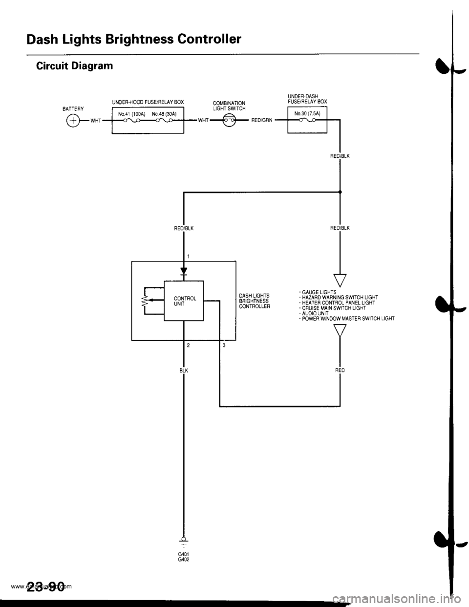
Dash Lights Brightness Controller
Circuit Diagram
23-90
G401
www.emanualpro.com
Page 1251 of 1395
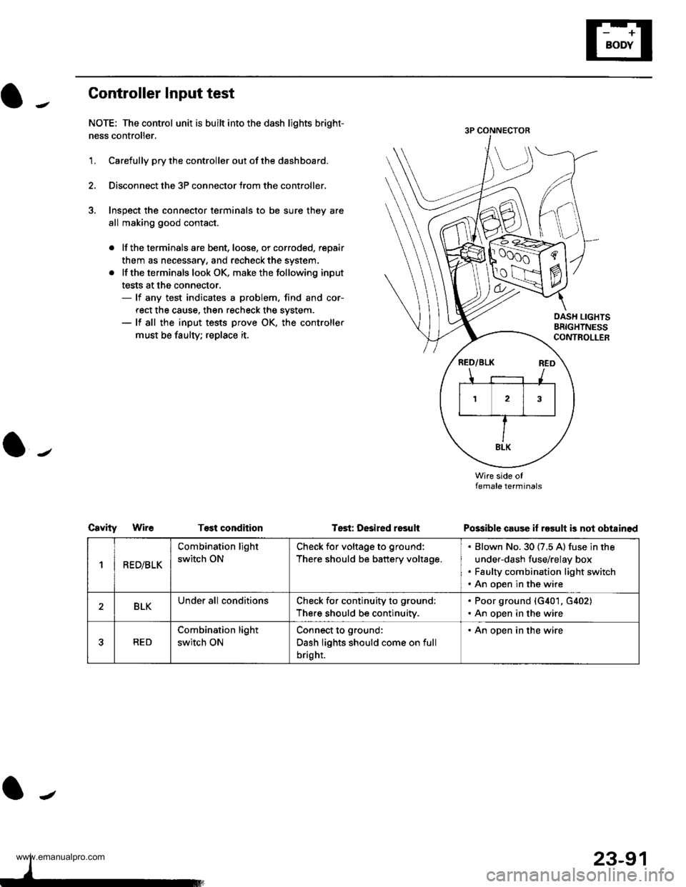
Controller Input test
NOTE: The control unit is built into the dash lights bright-
ness controller.
1.Carefully pry the controller out of the dashboard.
Disconnect the 3P connector trom the controller,
Inspect the connector terminals to be sure they are
all making good contact.
. lf the terminals are bent, loose, or corroded, repair
them as necessary, and recheck the system.
. lf the terminals look OK, make the following input
tests at the connector.- lf any test indicates a problem, find and cor-
rect the cause. then recheck the system.- lf all the input tests prove OK, the controller
must be taulty; replace it.
CsvityWireT€st condhion
Wire side oflemale terminals
Possible cause if result is not obi8inod
OASH LIGHTSBRIGHTNESSCONTROLLER
Tsst: Desired resuli
1R ED/BLK
Combination light
switch ON
Check for voltage to ground:
There should be battery voltage.
Blown No. 30 (7.5 A) fuse in the
under-dash fuse/relay box
Faulty combination light switch
An open in the wire
2BLKUnder all conditionsCheck for continuity to ground:
There should be continuitv.
. Poor ground (G401, G402). An open in the wire
5RED
Combination light
switch ON
Connect to ground:
Dash lights should come on full
bright.
. An open in the wire
23-91
www.emanualpro.com
Page 1265 of 1395
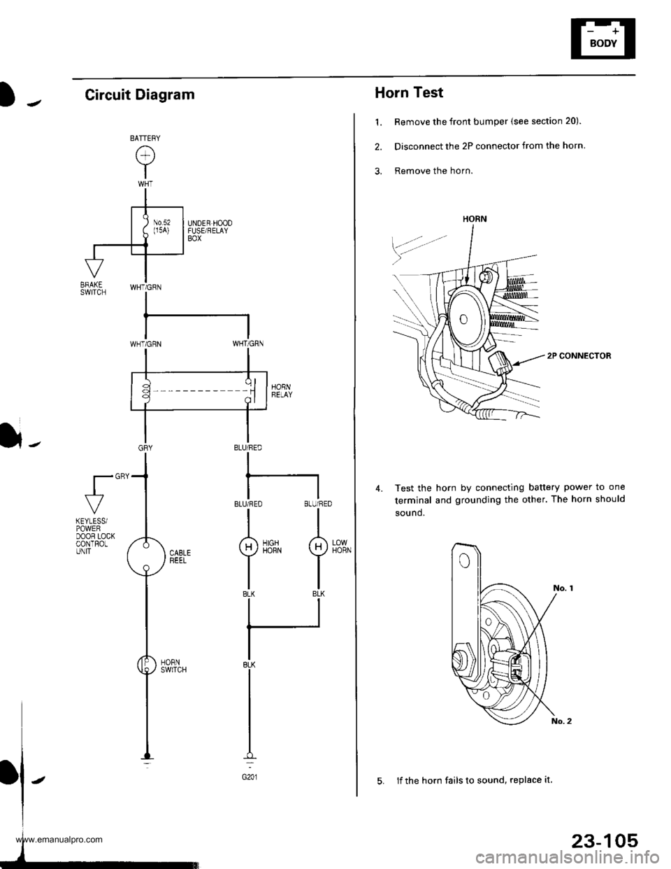
Horn Test
1. Remove the front bumper (see section 20).
2. Disconnect the 2P connector from the horn
3, Remove the horn.
2P CONNECTOR
Test the horn by connecting battery power to one
terminal and grounding the other. The horn should
sound.
4.
HORN
23-105
5. lf the horn fails to sound, replace it
Circuit Diagram
}-BLU/FED
I
BLUi FEO BLU/RED
II
g)iirrN I
tlBLK BLK
ll
IBLK
I
I
I
G201
fl"'
LOWHORN
KEYLESSiPOWEFDOOR LOCKCONTROLUNIT
www.emanualpro.com
Page 1271 of 1395
EI
IGNITIONSWTCH
-f "r?h\_--,' I
I
I
I
WHT/8LK +WHT
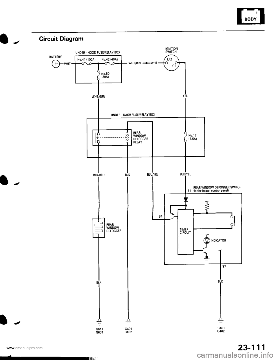
a-Circuit Diagram
BATTERY
@-*"
l-
IJ
l"8LK
G401G402
N0.41 {100A) N0.42 (404)
UNDER-HOOD FUSE/REI-AY BOX
REAs WINDOW DEFOGGER SWITCHB1 {in ihe heater control panel)
b}l!;r.r
23-111
www.emanualpro.com
Page 1273 of 1395
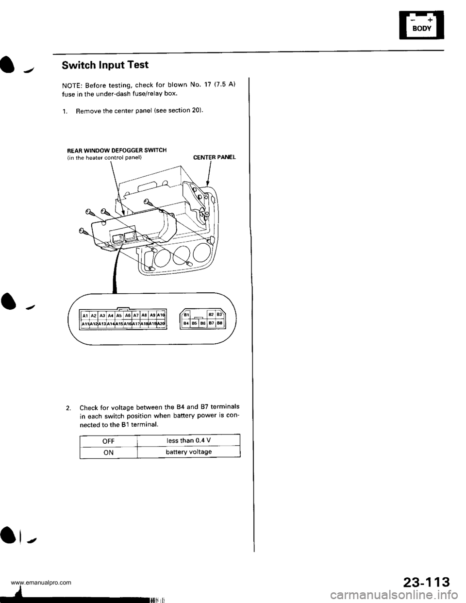
Switch Input Test
NOTE: Before testing, check for blown No. 17 (7.5 A)
fuse in the under-dash fuse/relay box.
1. Remove the center panel {see section 20).
REAR WINOOW DEFOGGER SWITCHlin the heater control oanel)CENTER PANEL
Check for voltage between the 84 and 87 terminals
in each switch position when battery power is con-
nected to the B l terminal.
OFFless than 0.4 V
ONbaftery voltage
Ol-
I
-
23-113
www.emanualpro.com
Page 1274 of 1395
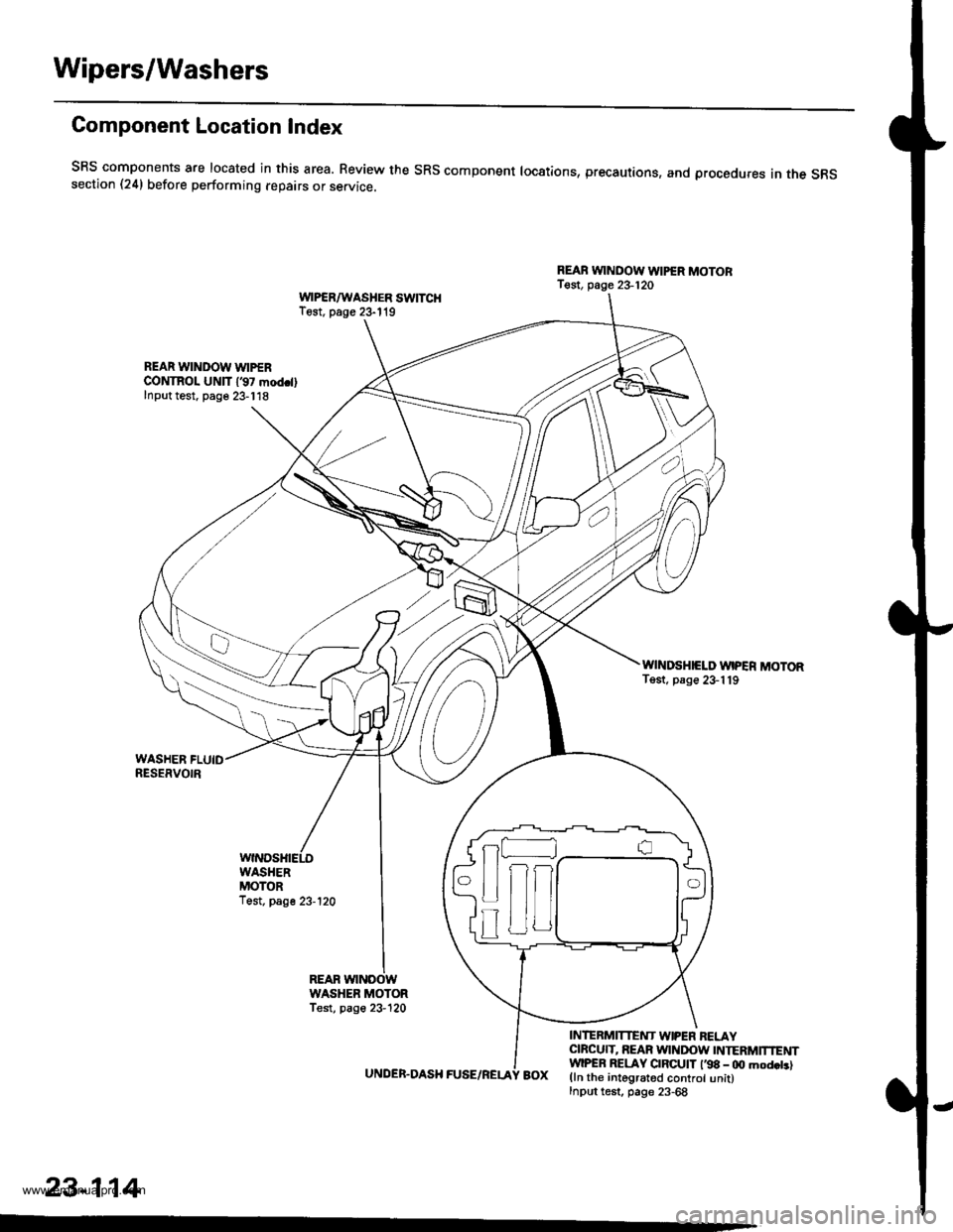
Wipers/Washers
Component Location Index
SRS components are located in this area. Review the SRs component locations, precautions, and procedures in the s6ssection (24) before performing repairs or service.
REAB WINDOW WIPER MOTOBT€st, page 23-120WPSR/WASHER SWITCHTest. page 23- l't9
REAR WINDOW WIPERCONTROL UNlT 137 mod.llInput test. page 23-118
WINDSHIELD WIPER MOTORTost, page 23-119
UNDER.DASH FUSE/RELA
INTERMITTENT W|PEN RELAYCIBCUIT, REAR WINDOW INTERMTNENTwlPER RELAY CIBCUIT l'98 - 0O mod.t.lBOX (ln the integrated control unit)Input test, page 23-68
23-114
-
n
tff
www.emanualpro.com
Page 1277 of 1395
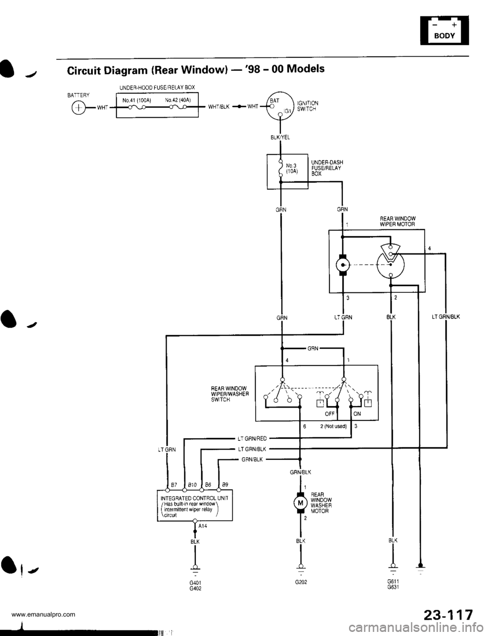
Circuit Diagram (Rear Windowl -'98 - 00 Models
BATTERYUNDER.HOOD FUSEi RELAY 80X
N0.41 (100A) N0.42 (40A)
@*,'WHT/BLK +WHTGNIT ONSW TCH
REAR WINDOWWPER MOTOR
Ot-
GRN/BLK
I
A n',$s".,,,
vil8t8E
IBLK
I
n-
G202
BLK
n_-:
G611G631
UNDEF-DASHFTJSE/RELAYBOX
JDLI OFF
INTEGRATED CONTROL UN T/Has bo ll-in re wndow\
t nlermillenl w per relay ]
BLK
.L-
G40lG402
I
-
23-117
www.emanualpro.com
