Head cover HONDA CR-V 1997 RD1-RD3 / 1.G Owner's Guide
[x] Cancel search | Manufacturer: HONDA, Model Year: 1997, Model line: CR-V, Model: HONDA CR-V 1997 RD1-RD3 / 1.GPages: 1395, PDF Size: 35.62 MB
Page 1239 of 1395
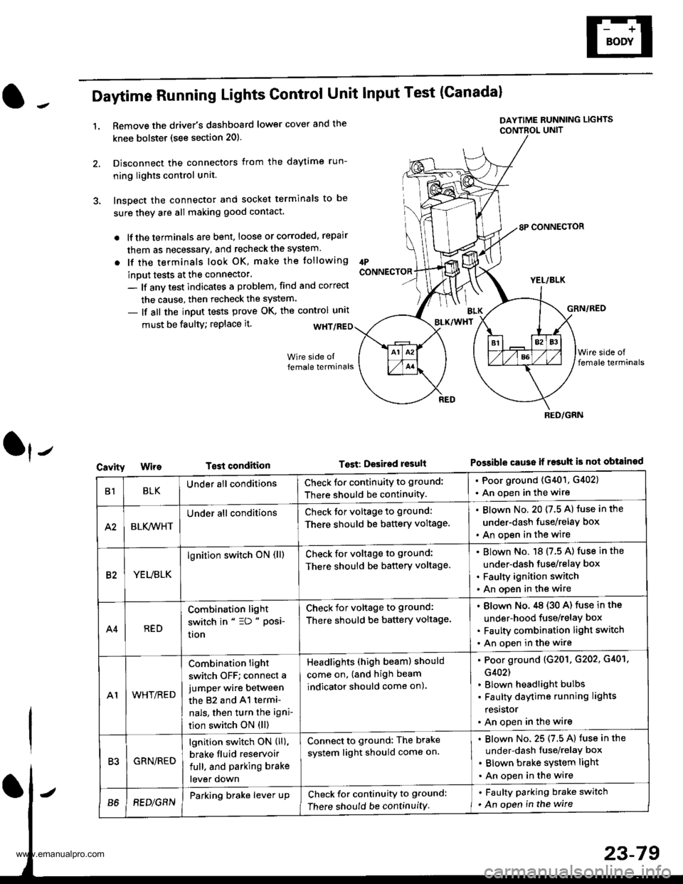
Daytime Running Lights Control Unit Input Test (Canadal
1.Remove the driver's dashboard lower cover and the
knee bolstet (see section 20).
Disconnect the connectors from the daytime run-
ning lights control unit.
Inspect the connector and socket terminals to be
sure they are all making good contact.
lf the terminals are bent, loose or corroded, repair
them as necessary, and recheck the system.
lf the terminals look OK, make the tollowing
inout tests at the connector'
- lf anv test indicates a problem, find and correct
the cause, then recheck the system.
- lf all the input tests prove OK, the control unrt
IPCONNECTOR
must be faulty; replace it.
T€st condition
DAYTIME RUNNING LIGHTS
CONTBOL UNIT
Tost: Desired result
8P CONNECTOR
YEL/BLK
GRN/RED
Possible cause ii r$uh is not obtained
BLK/WHT
Cavity
RED/GRN
B1BLKUnder all conditionsCheck for continuity to ground:
There should be continuity.
. Poor ground (G401, G402)
. An open in the wire
A2BLK,4iVHT
Under all conditionsCheck tor voltage to ground:
There should be battery voltage.
Blown No. 20 (7.5 A) luse in the
under-dash fuse/relay box
An open in the wire
82YEUBLK
lgnition switch oN (ll)Check for voltage to ground:
There should be battery voltage.
Blown No. 18 (7.5 A) fuse in the
under-dash tuse/relay box
Faulty ignition switch
An open in the wire
A4RED
Combination light
switch in " =D " Posi-
uon
Check for voltage to ground:
There should be battery voltage.
Blown No.,tg (30 A) fuse in the
under-hood fuse/relay box
Faulty combination light switch
An open in the wire
A1WHT/RED
Combination light
switch OFF; connect a
jumper wire between
the 82 and 41 termi-
nals, then turn the igni-
tion switch ON (ll)
Headlights (high beam) should
come on, (and high beam
indicator should come on).
Poor ground (G201. G202, G401,
G402)
Blown headlight bulbs
Faulty daytime running lights
resrslor
An open in the wire
R'IGRN/RED
lgnition switch ON (ll),
brake fluid reservoir
full. and parking brake
lever down
Connect to ground: The brake
system light should come on.
Blown No. 25 (7.5 A) fuse in the
under-dash fuse/relaY box
Blown brake system light
An open in the wire
B68EDlGRNParking brake lever upCheck for continuity to ground:
There should be continuity
. Faulty parking brake switch
. An open in the wire
www.emanualpro.com
Page 1241 of 1395
Adjustment
Bstore adiusting the headlights:
. Park the vehicle on level ground
. Make sure the fuel tank is tull
. The driver or someone who weighs the same should
sit in the driver's seat.
. Load the trunk with the items you usually carry'
. Push down on the front and rear bumpers several
times to make sure the vehicle is sitting normally'
CAUTION: Halogen headlights become very hot in use;
do not touch them or the atiaching hardware immedi-
ately after they have been turned off.
1. ODen the hood.
2. Remove the left inner fender {see section 20).
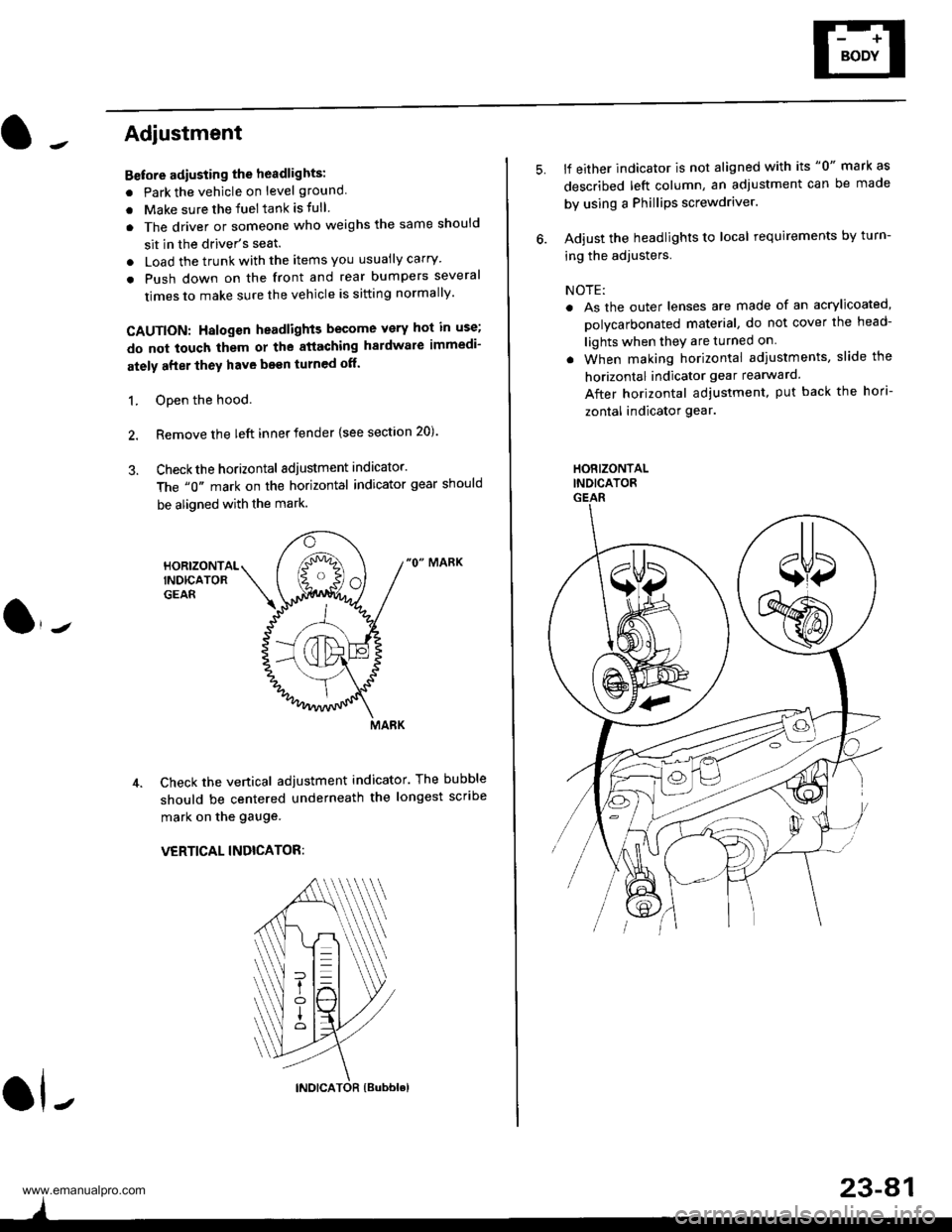
3. Checkthe horizontal adjustment indicator.
The "0" mark on the horizontal indicator gear should
be aligned with the mark.
"0" MARK
Check the vertical adjustment indicator. The bubble
should be centered underneath the longest scribe
mark on the gauge.
VERTICAL INDICATOR:
ol-
)
5.lf either indicator is not aligned with its "0" mark as
described left column, an adjustment can be made
by using a Phillips screwdriver.
Adjust the headlights to local requirements by turn-
ing the adjusters.
NOTE:
. As the outer lenses are made of an acrylicoated,
polycarbonated material, do not cover the head-
lights when they are turned on
. When making horizontal adiustments, slide the
horizontal indicator gear rearward.
After horizontal adjustment, put back the hori-
zontal indicator gear.
HORIZONTALINDICATORGEAR
23-A1
www.emanualpro.com
Page 1308 of 1395
Seat Belts
Chifd Seat Tether Anchor Installation -,97 - 99 Models
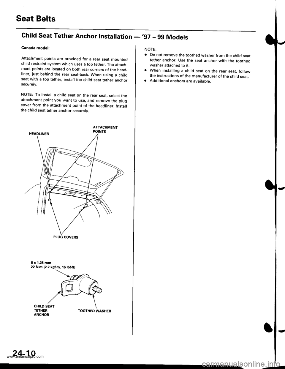
Canada model:
Attachment points are provided for a rear sear mountedchild restraint system which uses a top tether. The attach_ment points are located on both rear corners of the head_liner, just behind the rear seat-back. When using a childseat with a top tether, install the child seat tether anchorsecurelv.
NOTE: To install a child seat on the rear seat, select theattachment point you want to use, and remove the plugcover from the attachment point of the headliner. Installthe child seat tether anchor securely.
ATTACHMENTPOINTS
PLUG COVERS
CHILO SEATTETHERANCHORTOOTHED WASHER
24-10
-4
NOTE:
. Do not remove the toothed washer from the child seattether anchor. Use the seat anchor with the toothedwasher attached to it.. When installing a child seat on the rear seat, followthe instructions of the manufacturer of the child seat.. Additional anchors are available.
-
www.emanualpro.com
Page 1309 of 1395
lrChild Seat Tether Anchor Removal/lnstallation -'00 Model
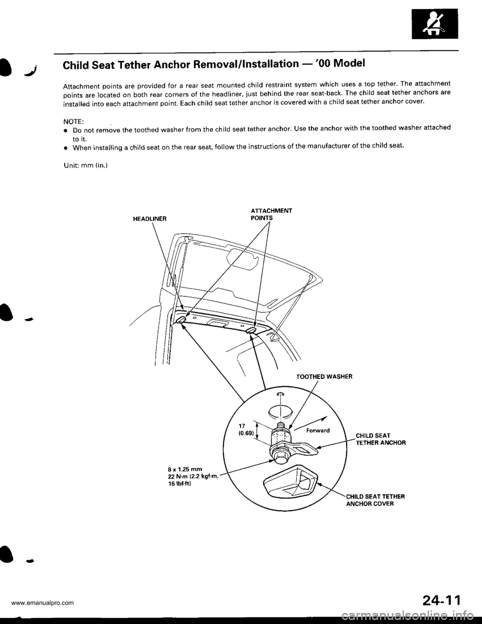
Attachment Doints are provided for a rear seat mounted child restraint system which uses a top tether' The attachment
points are located on both rear corners of the headliner, just behind the rear seat-back The child seat tether anchors are
installed into each attachment point. Each child seat tether anchor is covered with a child seat tether anchor cover.
NOTE:
. Do not remove the toothed washer from the child seat tether anchor. Use the anchor with the toothed washer attached
to it.
. When installing a child seat on the rear seat, follow the instructions of the manufacturer of the child seat.
Uniti mm (in.)
HEADLINER
TOOTHEO WASHEB
CHILD SEATTETHER ANCHOR
I x '1.25 mm22 N.m (2.2 kgf m,
16 rbf.ft)
24-11
www.emanualpro.com
Page 1388 of 1395
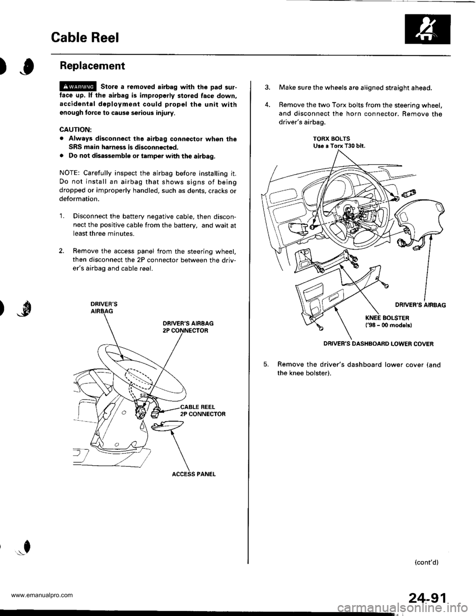
Cable Reel
)Replacement
@ stors a removed airbag with the pad sur-
tace up. lf th€ airbag is improperly stored face down,
accidental d6ployment could propel the unit withgnough force to cause serious iniuty.
CAUTION:
. Always disconnect the airbag connector whgn the
SRS msin harness is disconnoctod.
. Do not disassemblo or tamper with the airbag.
NOTE: Carefully inspect the airbag before installing it.
Do not install an airbag that shows signs of being
dropped or improperly handled, such as dents, cracks or
deformation,
'1.Disconnect the battery negative cable, then discon-
nect the positive cable from the battery, and wait at
least three minutes.
Remove the access panel from the steering wheel,
then disconnect the 2P connector between the driv-
er's airbag and cable reel.
*f
DRIVER'S
24-91
Make sure the wheels are aligned straight ahead.
Remove the two Torx bolts from the steering wheel,
and disconnect the horn connector, Remove the
driver's airbag,
TORX BOLTSUse a Torx T30 bit.
5. Remove the driver's dashboard lower cover (and
the knee bolster).
(cont'd)
DRIVER'S DASHBOARD LOWER COVER
www.emanualpro.com
Page 1390 of 1395
)o
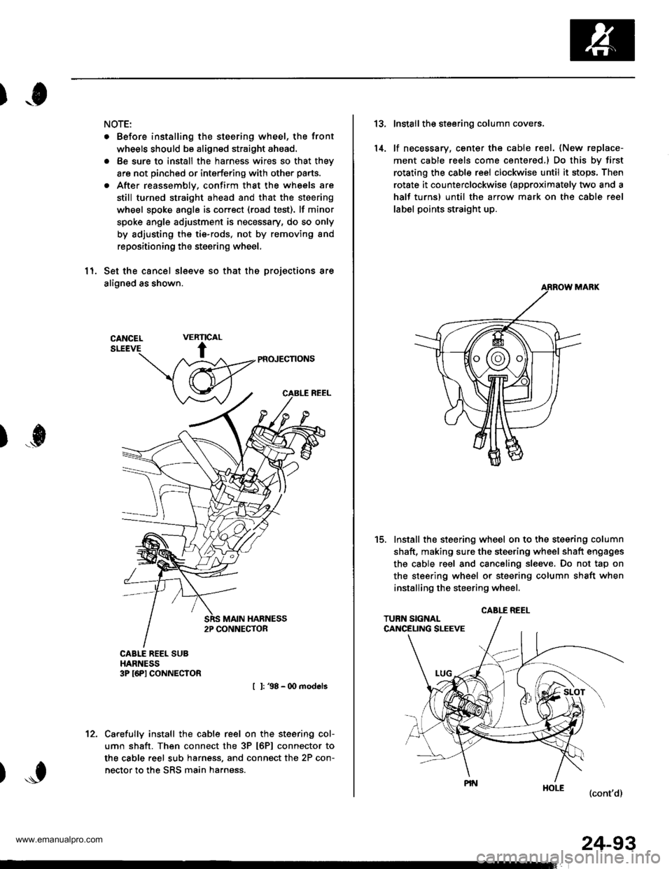
NOTE:
. Before installing the steering wheel, the front
wheels should be aligned straight ahead.
. Be sure to install the harness wires so that they
are not pinched or interfering with other parts.
. After reassemblv, confirm that the wheels are
still turned straight ahead and that the steering
wheel spoke angle is correct (road test). lf minor
spoke angle adjustment is necessary, do so only
by adjusting the tie-rods, not by removing and
repositioning the steering wheel,
11. Set the cancel sleeve so that the projections are
aligned as shown.
PR(NECNONS
I l: 38 - 00 models
Carefully install the cable reel on the steering col-
umn shaft. Then connect the 3P t6Pl connector to
the cable reel sub harness, and connect the 2P con-
nector to the SRS main harness.
RIC
t
VEAL
)...0
't2.
24-93
13.
14.
Install the steering column covers.
lf necessary, center the cable reel. {New replace-
ment cable reels come centered,l Do this by first
rotating the csble reel clockwise until it stops, Then
rotate it counterclockwise (approximately two and a
half turns) until the arrow mark on the cable reel
label points straight up.
Install the steering wheel on to the steering column
shaft, making sure the steering wheel shaft engages
the cable reel and canceling sl€eve. Do not tap on
the steering wheel or steering column shaft when
installing the steering wheel.
(cont'd)
t5.
CABLE REEL
www.emanualpro.com