Steering shaft HONDA CR-V 1997 RD1-RD3 / 1.G Owner's Guide
[x] Cancel search | Manufacturer: HONDA, Model Year: 1997, Model line: CR-V, Model: HONDA CR-V 1997 RD1-RD3 / 1.GPages: 1395, PDF Size: 35.62 MB
Page 1206 of 1395

Ground Distribution
Ground-to-Component(sl Index
GroundWire Color
G2
G3
G 10'l
G201
G202
G351
BLIVRED
BRN
BLK
BLK
BRN/BLK
BLK
BLK
BLK
23-46
Component or Circuits Grounded
Battery
Valve Cover
Transmission housing
A,/T gear position switch
ECM (PG1, PG2) ('98 - 00 models: M/T)
PCM (PG1, PG2l (Avrr)
PGM-FI main relay
Power steering pressure (PSP) switch
Radiator fan switch
VSS
Data link connector
ECM (1G1, LG2) ('98 - 00 models: M/T)
PCM (LGI, LG2) (IVT)
Shielding:
between ECM ('98 - 00 models: M/T) or PCM (Ay'T) and CKF sensorbetween ECM {'98 - 00 modets: M/T} or pCM (Ay'T) and CKp sensorbetween ECM ('98 - 00 models: M/T) or PCM (rVT) and CYP sensorbetween ECM ('98 - 00 models: M/T) or PCM (Ay'T) and TDC sensorbetween ECM {'98 - 00 models: M/T) or PCM (ly'T) and countershaft speed sensor (Ay'T)
between ECM ('98 - 00 models: M/T) or PCM {A,,/T) and mainshaft sp€ed sensor {!VT)between ECM ('98 - 00 models: M/T) or PCM (A,/T) and primary HO2Sbetween ECM ('98 - 00 models: M/T) or PCM (Ay'T) and secondary HO2SHorn (High)
Horn {Low}
Radiator fan motor
Right headlight
Right front parking light
Right front side marker light
Right front turn signal light
Condenser fan motor
Cruise actuator
Left front parking light
Left front side marker light
Left front turn signal light
Left headlight
Rear window washer motor
Windshield washer motor
ABS pump motor
www.emanualpro.com
Page 1389 of 1395

Gable Reel
Replacement (cont'dl
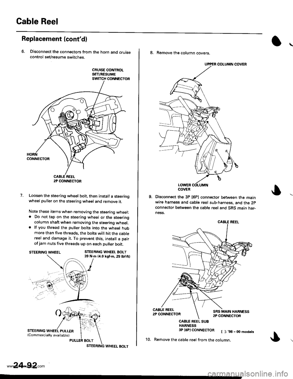
6, Disconnect the connectors from the horn and cruisecontrol sevresume switches.
cRursE coNtRoLSET/RESUMESWITCH CONNECTOR
1.Loosen the steering wheel bolt, then install a steeringwheel puller on the steering wheel and remove it.
Note these items when removing the stee.ing wheel:. Do not tap on the steering wheel or the steeringcolumn shaft when removing the steering wheel,. lf you thread the puller bolts into the wheel hubmore than five threads, the bolts will hit the cablereel and damage it. To prevent this. install a pair
of jam nuts five threads up on each puller bolt.
STEERING WHEEL BOLT39 N.m 14.0 kgf.m. 29 lbf.ftlSTEERING WHEEL
STEERING
2P CONNECTOR
24-92
8. Remove the column covers,
Disconnect the 3P [6P] connector between the mainwire harness and cable reel sub-harness, and the 2pconnector between the cable reel and SRS main har-ness.
CAALE REEL SU8HARNESS3P l6Pl CONNECTOR [ ]:,98_00modets
10. Remove the cable reelfrom the cotumn,
COVER
www.emanualpro.com
Page 1390 of 1395

)o
NOTE:
. Before installing the steering wheel, the front
wheels should be aligned straight ahead.
. Be sure to install the harness wires so that they
are not pinched or interfering with other parts.
. After reassemblv, confirm that the wheels are
still turned straight ahead and that the steering
wheel spoke angle is correct (road test). lf minor
spoke angle adjustment is necessary, do so only
by adjusting the tie-rods, not by removing and
repositioning the steering wheel,
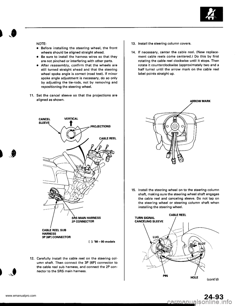
11. Set the cancel sleeve so that the projections are
aligned as shown.
PR(NECNONS
I l: 38 - 00 models
Carefully install the cable reel on the steering col-
umn shaft. Then connect the 3P t6Pl connector to
the cable reel sub harness, and connect the 2P con-
nector to the SRS main harness.
RIC
t
VEAL
)...0
't2.
24-93
13.
14.
Install the steering column covers.
lf necessary, center the cable reel. {New replace-
ment cable reels come centered,l Do this by first
rotating the csble reel clockwise until it stops, Then
rotate it counterclockwise (approximately two and a
half turns) until the arrow mark on the cable reel
label points straight up.
Install the steering wheel on to the steering column
shaft, making sure the steering wheel shaft engages
the cable reel and canceling sl€eve. Do not tap on
the steering wheel or steering column shaft when
installing the steering wheel.
(cont'd)
t5.
CABLE REEL
www.emanualpro.com