clearance HONDA CR-V 1997 RD1-RD3 / 1.G Service Manual
[x] Cancel search | Manufacturer: HONDA, Model Year: 1997, Model line: CR-V, Model: HONDA CR-V 1997 RD1-RD3 / 1.GPages: 1395, PDF Size: 35.62 MB
Page 459 of 1395
Reverse Shift Holder
Clearance Inspection
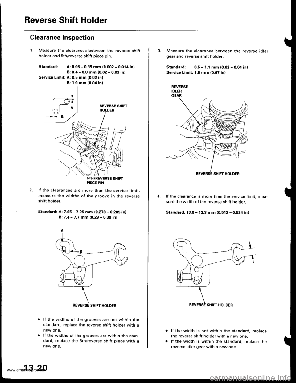
1.Measure the clearances between the reverse shift
holder and sth/reverse shift Diece Din.
Standard:A: 0.05 - 0.35 mm (0.002 - 0.014 in)
8: 0.4 - 0.8 mm 10.02 - 0.03 inl
Service Limit: A: 0.5 mm (0.02 in)
B: 1.0 mm 10.0,[ in]
2.lf the clearances are more than the service limit.
measure the widths of the groove in the reverse
shift holder.
Standard: A: 7.05 - 7.25 mm {0.278 - 0.285 inl
B: 7.4 - 7.7 mm (0.29 - 0.30 inl
lf the widths of the grooves are not within thestandard, replace the reverse shift holder with a
new one.
lf the widths of the grooves are within the stan-
dard, replace the sth/reverse shift piece with anew one.
PIECE PIN
REVERSE SHIFT HOLDER
13-20
3. Measure the clearance between the reverse idler
gear and reverse shift holder.
Standard: 0.5 - 1.1 mm {0.02 - 0.0i1 in}
Service Limit: 1.8 mm (0.07 in)
REVERSEIDLERGEAR
lf the clearance is more than the service limit. mea-
sure the width ot the reverse shift holder.
Standard: 13.0 - 13.3 mm (0.512-0521inl
It the width is not within the standard, replace
the reverse shift holder with a new one.
lf the width is within the standard, reolace the
reverse idler gear with a new one.
www.emanualpro.com
Page 461 of 1395
Shift Fork Assembly
Clearance Inspection
NOTE: The synchro sleeve and synchro hub should be
reolaced as a set.
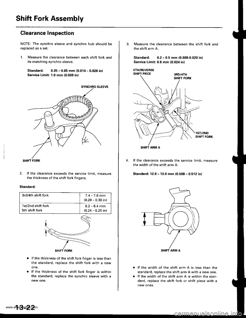
1. Measure the clearance between each shift fork and
its matching synchro sleeve.
Standard: 0.35 - 0.65 mm 10.01/t - 0.026 inl
Service Limit: 1,0 mm {0.039 inl
SHIFT FORK
2. lf the clearance exceeds the service limit. measure
the thickness of the shift fork fingers.
Standard:
lf the thickness of the shift fork finger is less than
the standard, replace the shift fork with a new
one.
lf the thickness of the shift fork tinger is within
the standard, replace the synchro sleeve with a
new one.
3rd/4th shift fork7.4 - 7.6 mm
(0.29 - 0.30 in)
1sv2nd shift fork
5th shift fork
6.2 - 6.4 mm(0.24 - 0.25 in)
3. Measure the clearance between the shift fork and
the shift arm A.
Standard; 0.2 - 0.5 mm (0.008-0.020 in)
Service Limit: 0.6 mm (0.02i1 in)
sTH/REVERSESHIFT PIECE ran,rru
lST/2NDSI{IFT FORK
lf the clearance exceeds the service limit, measure
the width of the shift arm A.
Standard: 12.9 - 13.0 mm 10.508 - 0.512 inl
lf the width of the shift arm A is less than the
standard, reDlace the shift arm A with a new one.
lf the width of the shift arm A is within the stan-
dard, replace the shift fork or shift piece with a
new ones.
www.emanualpro.com
Page 463 of 1395
Mainshaft Assembly
Clearance Inspection
NOTE; lf replacement is required, always replace the
synchro sleeve and hub as a set.
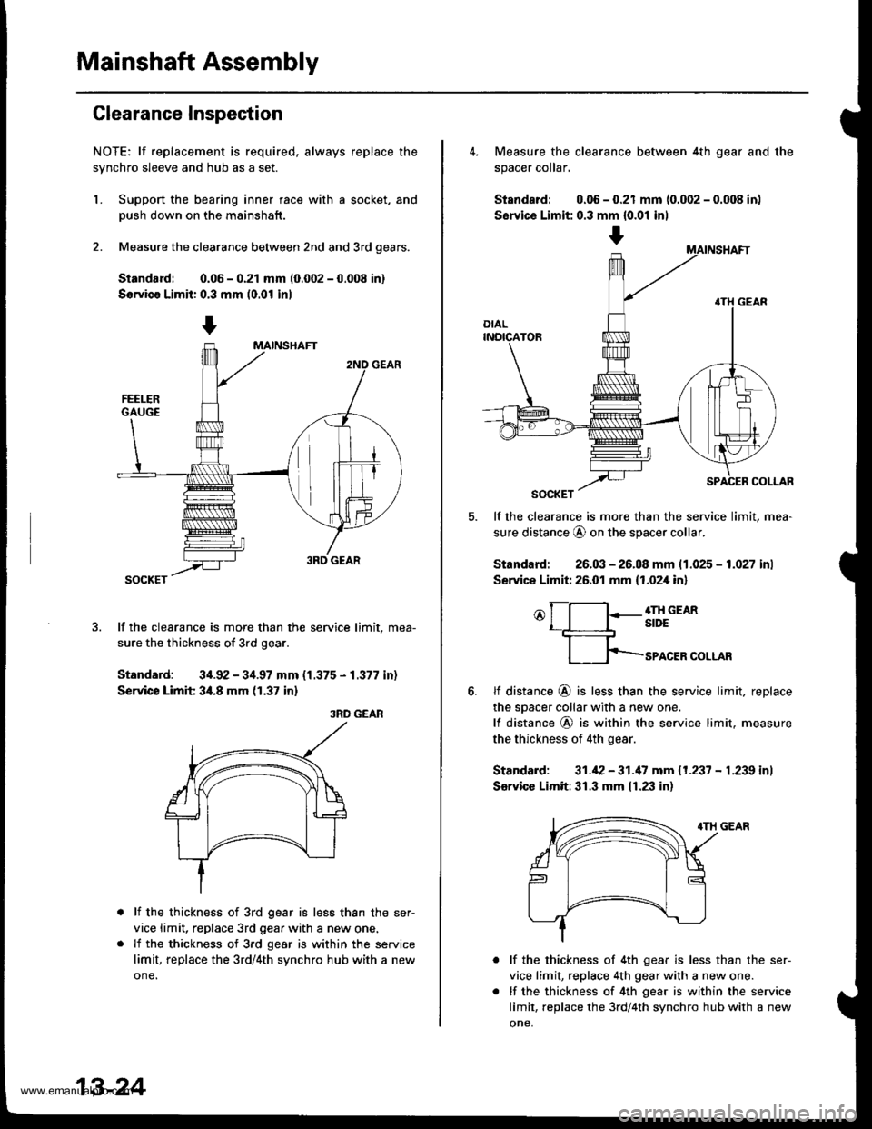
L Support the bearing inner race with a socket. and
Dush down on the mainshaft.
2. Measure the clearance between 2nd and 3rd oears.
Siandard: 0.06 - 0.21 mm 10.002 - 0.008 in)
Servica Limit: 0.3 mm (0.01 in)
lf the clearance is more than the service limit, mea-
sure the thickness of 3rd gear.
Standard: 34.92 - 34.97 mm {1.375 - 1.377 in)
Service Limit 34.8 mm (1.37 in)
3RD GEAR
lf the thickness of 3rd gear is less than the ser-
vice limit, replace 3rd gear with a new one.
lf the thickness of 3rd gear is within the service
limit, replace the 3rd/4th synchro hub with a new
one.
13-24
+
4. Measure the clearance between 4th gear and the
spacer coIar,
Standard: 0.06 - 0.21 mm {0.002 - 0.008 in)
Servic€ Limit: 0.3 mm {0.01 inl
lf the clearance is more than the service limit, mea-
sure distance @ on the spacer collar,
Standard: 26.03 - 26.08 mm {1.025 - 1.027 inl
Service Limit: 26.01 mm {1.02,[ in]
o[-l:-g;;em
fp-rro.ERcoLLAR
6.tf distance @ is less than the service limit, replace
the sDacer collar with a new one.
lf distance @ is within the service limit. measure
the thickness of 4th gear.
Standard: 31.42 - 31.'17 mm 11.237 - L239 inl
Sarvicc Limit:31.3 mm {1.23 in)
lf the thickness of 4th gear is less than the ser-
vice limit, replace 4th gear with a new one.
lf the thickness of 4th gear is within the service
limit, replace the 3rd/4th synchro hub with a new
one,
www.emanualpro.com
Page 464 of 1395
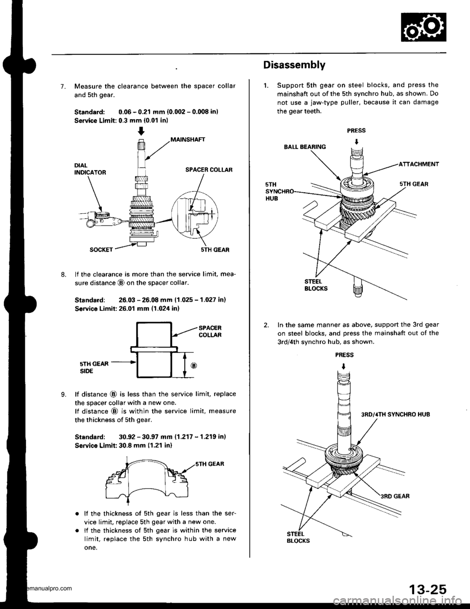
7. Measure the clearance between the spacer collar
and 5th gear.
Standard: 0.06 - 0.21 mm {0.002 - 0.008 in)
Service Limit: 0.3 mm {0.01 in)
MAINSHAFT
SPACER COLLAR
8.
SOCKET5TH GEAR
lf the clearance is more than the service limit, mea-
sure distance @ on the spacer collar
Standard: 26.03 - 26.08 mm 11.025 - 1.027 in)
S€rvico Limit: 26.01 mm (1.024 in)
9.
SPACERCOLLAR
5TH GEARSIDE
lf distance @ is less than the service limit, replace
the spacer collar with a new one.
lf distance @ is within the service limit, measure
the thickness of sth gear.
Standard: 30.92 - 30.97 mm (1.217 - 1.219 in)
Service Limit: 30.8 mm (1.21 in)
r-- ,,srH GEAR
gt Fq
I .J'-----!--\--J-l
lf the thickness of 5th gear is less than the ser-
vice limit, replace 5th gear with a new one.
li the thickness of sth gear is within the service
limit, replace the sth synchro hub with a new
one.
Disassembly
1. Support 5th gear on steel blocks, and press the
mainshaft out of the 5th synchro hub, as shown. Do
not use a jaw-type puller, because it can damage
the gear teeth.
PRESS
I
ACHMENT
In the same manner as above, support the 3rd gear
on steel blocks. and press the mainshaft out of the
3rd/4th svnchro hub, as shown.
PRESS
I
BLOCKS
www.emanualpro.com
Page 468 of 1395
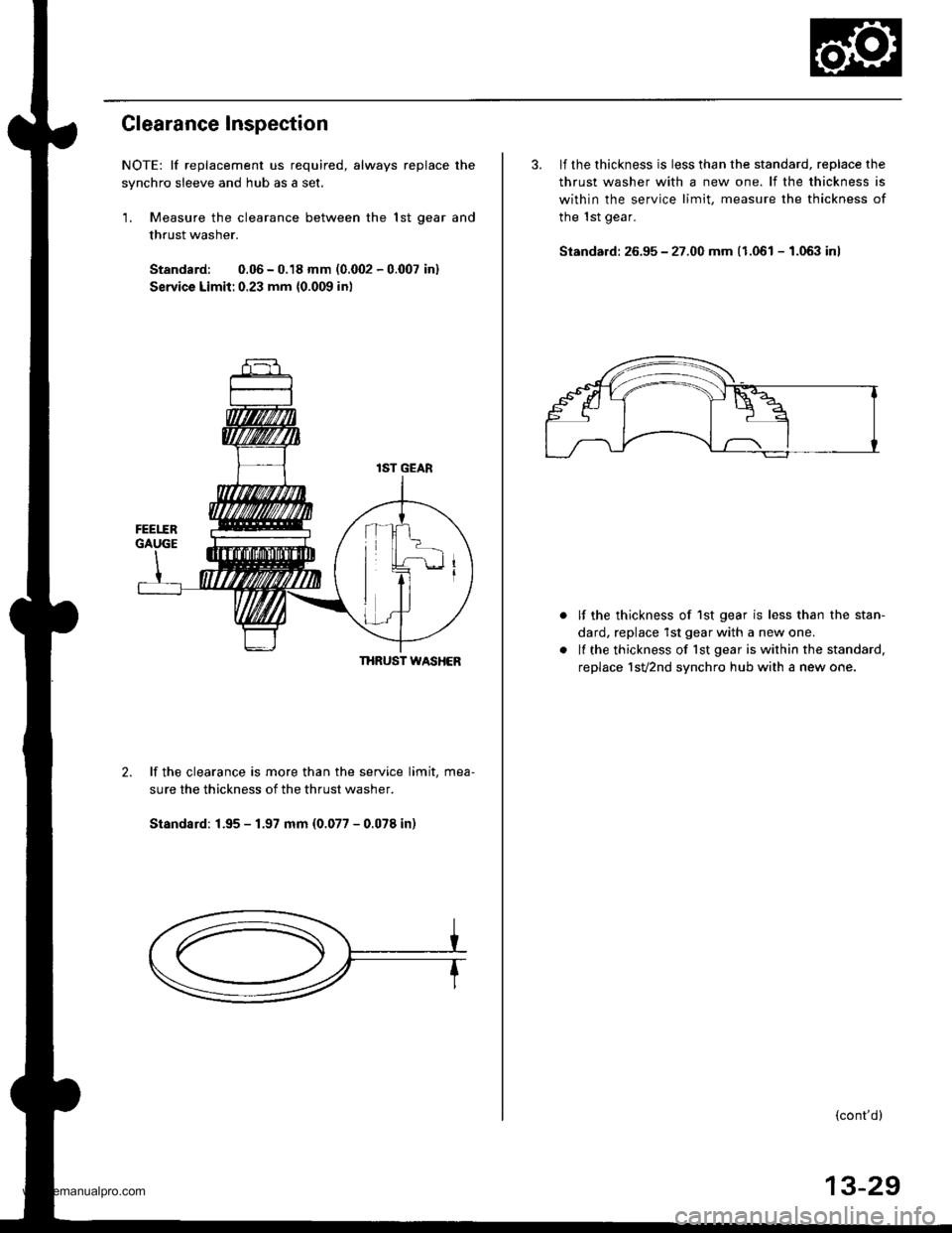
Clearance Inspection
NOTE: lf replacement us required, always replace the
synchro sleeve and hub as a set.
1. Measure the clearance between the lst oear and
thrust washer.
Standard: 0.06 - 0.18 mm (0.@2 - 0.007 in)
Servica Limit:0.23 mm {0.009 in)
THRUST WASHER
2.lf the clearance is more than the service limit, mea-
sure the thickness of the thrust washer.
Standsrd: 1.95 - 1.97 mm (0.077 - 0.078 in)
3. lf the thickness is less than the standard, reDlace the
thrust washer with a new one. lf the thickness is
within the service limit, measure the thickness of
the 1st gear.
Standard: 26.95 - 27.00 mm (1.061 - 1.063 inl
lf the thickness of 1st gear is less than the stan-
dard, replace 1st gear with a new one.
lf the thickness of lst gear is within the standard.
replace 1sv2nd synchro hub with a new one.
{cont'd}
13-29
www.emanualpro.com
Page 469 of 1395
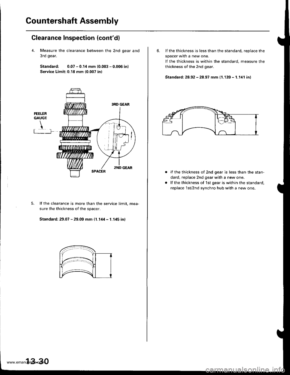
Countershaft Assembly
Clearance Inspection (cont'dl
4. Measure the clearance between the 2nd qear and
3rd gear.
Standard: 0.07 - 0.1,1 mm (0.003 - 0.006 inl
Service Limit:0.18 mm (0.007 inl
FEET.ERGAUGE
!t .�-]�
lf the clearance is more than the service limit. mea-
sure the thickness of the spacer.
Standard: 29.07 - 29.09 mm (l.14il - 1.145 inl
13-30
6. lf the thickness is less than the standard, reDlace the
spacer wrln a new one.
lf the thickness is within the standard, measure the
thickness of the 2nd gear.
Standald: 28.92 - 28.97 mm (1.139 - 1.141 in)
lf the thickness of 2nd gear is less than the stan-
dard, replace 2nd gear with a new one.
lf the thickness of lst gear is within the standard,
replace 1sv2nd synchro hub with a new one.
www.emanualpro.com
Page 476 of 1395
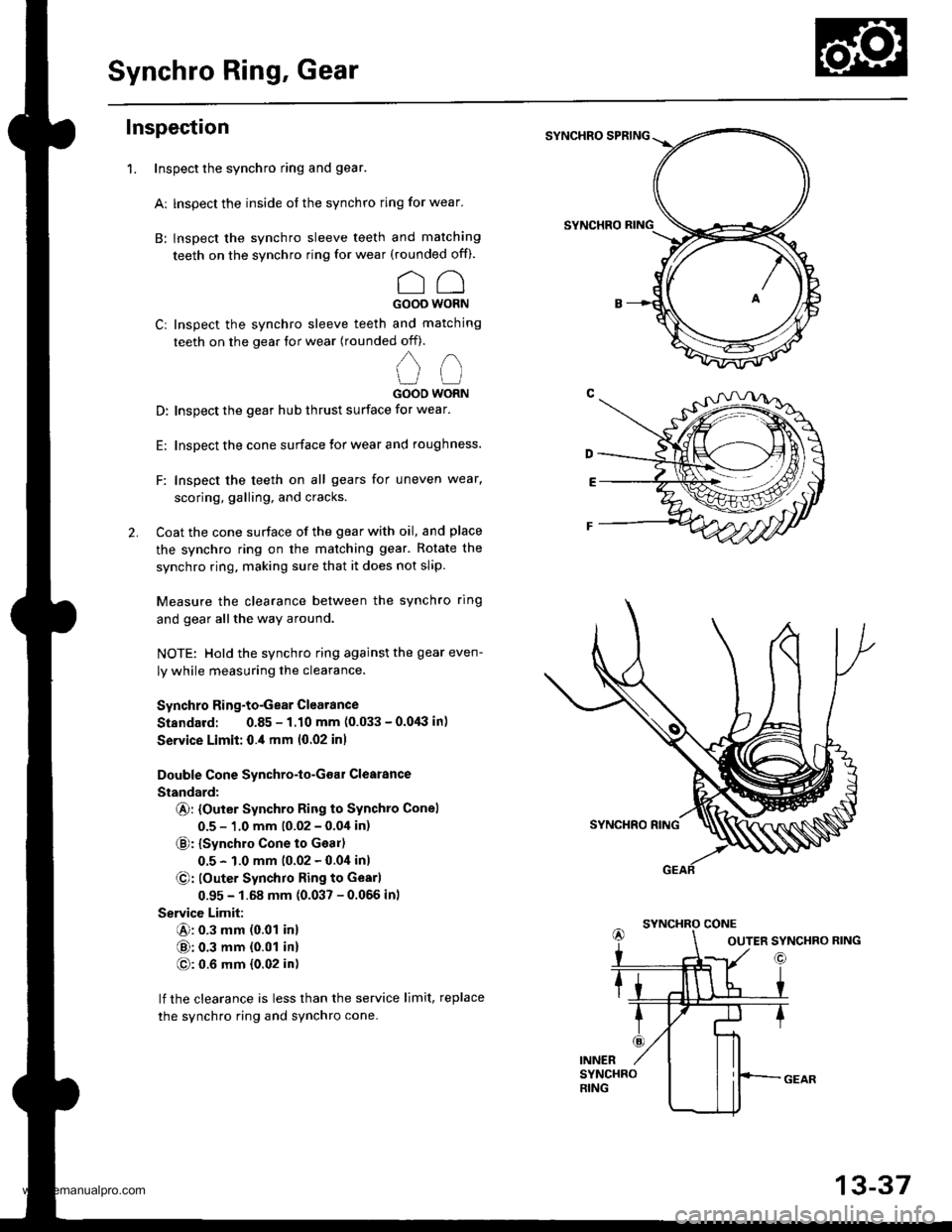
Synchro Ring, Gear
Inspection
Inspect the synchro ring and gear.
Ar lnspect the inside of the synchro ring for wear.
B: lnspect the synchro sleeve teeth and matching
teeth on the synchro ring for wear (rounded of0.
CCGOOO WORN
Cr Inspect the synchro sleeve teeth and matching
teeth on the gear tor wear (rounded off).
,,
u (-l
GOOO WORN
D: Inspect the gear hub thrust surface for wear.
E: Inspect the cone surface lor wear and roughness.
F: Inspect the teeth on all gears for uneven wear,
scoring, galling, and cracks.
2. Coat the cone surface of the gear with oil, and place
the synchro ring on the matching gear. Rotate the
synchro ring, making sure that it does not slip.
Measure the clearance between the synchro ring
and gear allthe way around.
NOTE: Hold the synchro ring against the gear even-
ly while measuring the clearance.
Synchro Ring-to-Gear Clearance
Standard: 0.85 - 1.10 mm (0.033 - 0.0,lil in)
Service Limit: 0.,1 mm 10.02 inl
Double Cone Synchro-lo-Goar Clearance
Standard:
@: {Outer Synchro Ring to Synchto Conel
0.5 - 1.0 mm (0.02 - 0.04 in)
€): {synchro cone to Geal)
0.5 - 1.0 mm (0.02 - 0.0i1inl
@: louter Synchro Ring to Gearl
0.95 - 1.68 mm (0.037 - 0.056 inl
Service Limit:
@: 0.3 mm (0.01 inl
@: 0.3 mm {0.01 in}
@: 0.6 mm {0.02 in)
lf the clearance is less than the service limit, replace
the synchro ring and synchro cone.
SYNCHRO SPRING
SYNCHRO
1.
OUTER SYNCHRO RING
13-37
www.emanualpro.com
Page 479 of 1395
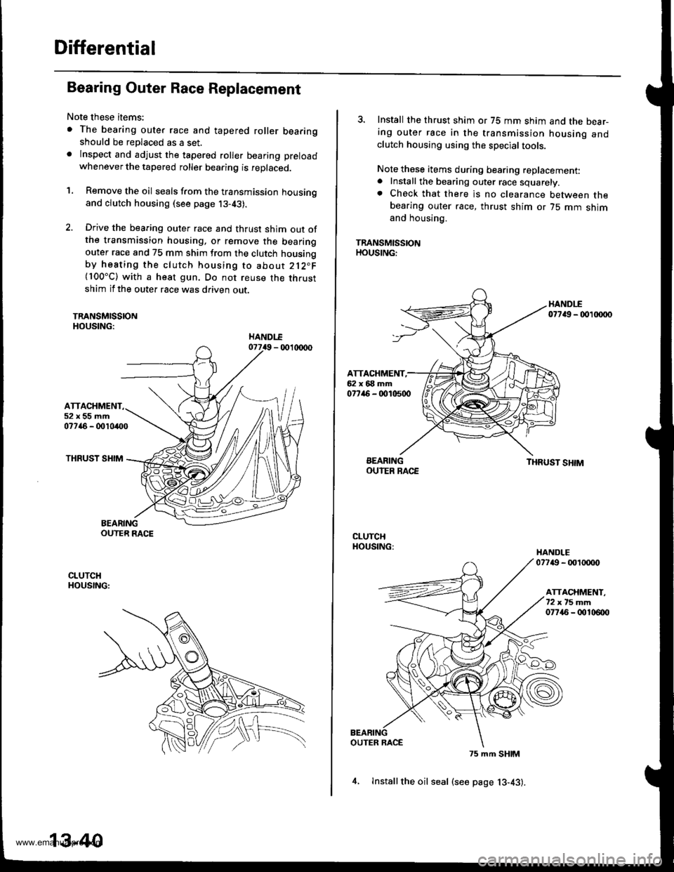
Differential
Bearing Outer Race Replacement
Note these items:
. The bearing outer race and tapered roller bearingshould be replaced as a set.. lnspect and adjust the tapered roller bearing preload
whenever the tapered roller bearing is replaced.
'1. Remove the oil seals from the transmission housingand clutch housing (see page j3-43).
2. Drive the bearing outer race and thrust shim out ofthe transmission housing, or remove the bearingouter race and 75 mm shim from the clutch housingby heating the clutch housing to about 212"F(100"C) with a heat gun. Do not reuse the thrustshim if the outer race was driven out.
TRANSMISSIONHOUSING:
ATTACHMENT52x55mm07746 - 0010400
THRUST SHIM
BEARINGOUTER RACE
CLUTCHHOUSING:
13-40
4, lnstallthe oil seal (see page 13-43).
3. Install the thrust shim or 75 mm shim and the bear-ing outer race in the transmission housing andclutch housing using the special tools.
Note these items during bearing replacement:. Install the bearing outer race squarely.. Check that there is no clearance between thebearing outer race, thrust shim or 75 mm shimand housing.
TRANSMISSIONHOUSING:
HANDI-E07749 - 00 xxto
ATTACHMENT,62x68mm077ir6 - 0010500
BEARINGOUIER RACETHRUST SHIM
CLUTCHHOUSING:HANDLE07749 - 001tXX)o
ATTACHMENT.72xt5mm07745 - 00106{x)
OUTER RACE
75 mm SHIM
www.emanualpro.com
Page 503 of 1395
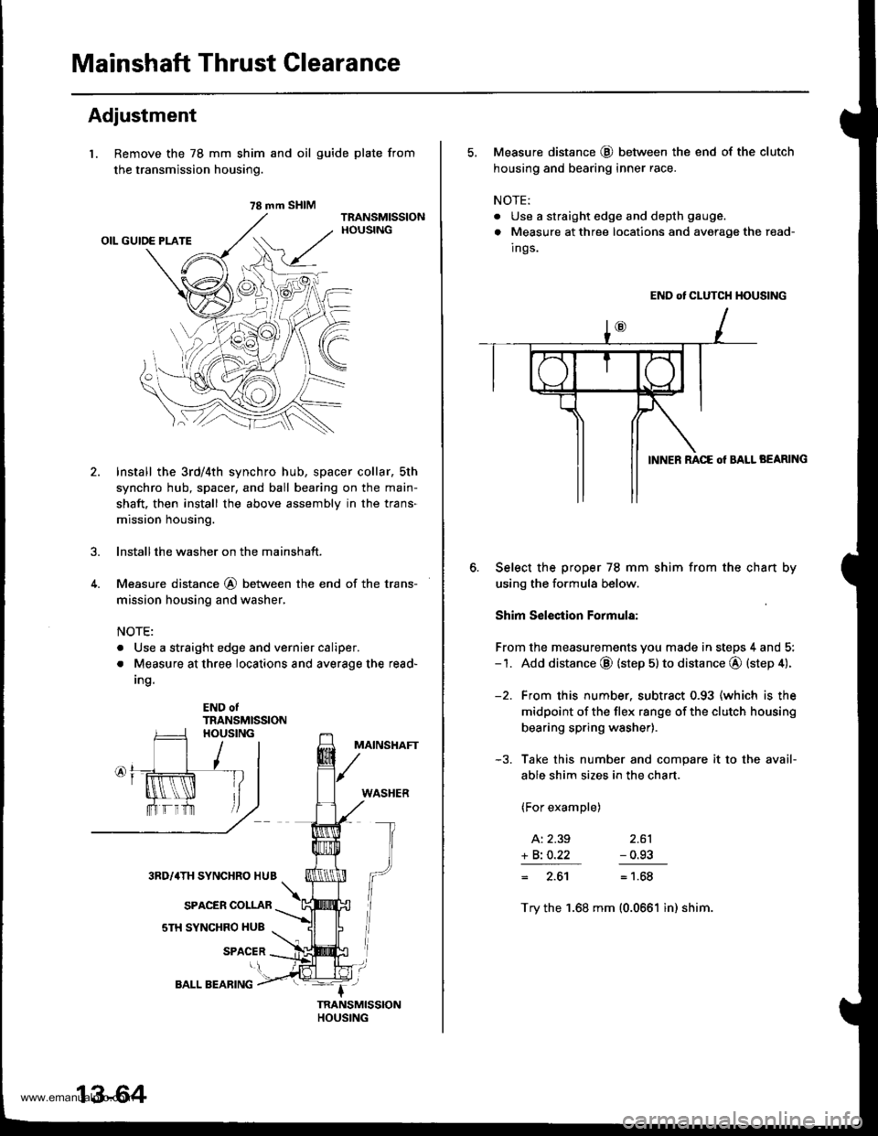
Mainshaft Thrust Clearance
Adjustment
l. Remove the 78 mm shim
the transmission housing.
4.
and oil guide plate from
Install the 3rd/4th synchro hub, spacer collar, sth
synchro hub, spacer, and ball bearing on the main-
shaft. then install the above assembly in the trans-
mission housing.
lnstallthe washer on the mainshaft.
Measure distance @ between the end of the trans-
mission housing and washer,
NOTE:
. Use a straight edge and vernier caliper.
. Measure at three locations and average the read-
Ing.
END otTRANSMISSION
MAINSHAFT
WASHER
3RD/4TH SYNCHRO HUB
SPACER COLLAR
sTH SYNCHRO HUB
SPACER
78 mm SHIM
13-64
BALL BEARING
5, Measure distance @ between the end of the clutch
housing and bearing inner race.
NOTE:
. Use a straight edge and depth gauge.
. Measure at three locations and avorage the read-
Ings.
END ot CLUTCH HOUSING
BEARING
Select the proper 78 mm shim from the chan by
using the formula below.
Shim S€lection Formula:
From the measurements you made in steps 4 and 5:-1. Add distance @ (step 5) to distance @ (step 4).
-2. From this number. subtract 0.93 (which is the
midpoint of the flex range of the clutch housing
bearing spring washer).
-3. Take this number and compare it to the avail-
able shim sizes in the chart.
(For example)
A: 2.39 2.61
+ Bi O.22 - 0.93
= 2.61= 1.68
Try the 1.68 mm (0.0661 in) shim.
www.emanualpro.com
Page 504 of 1395
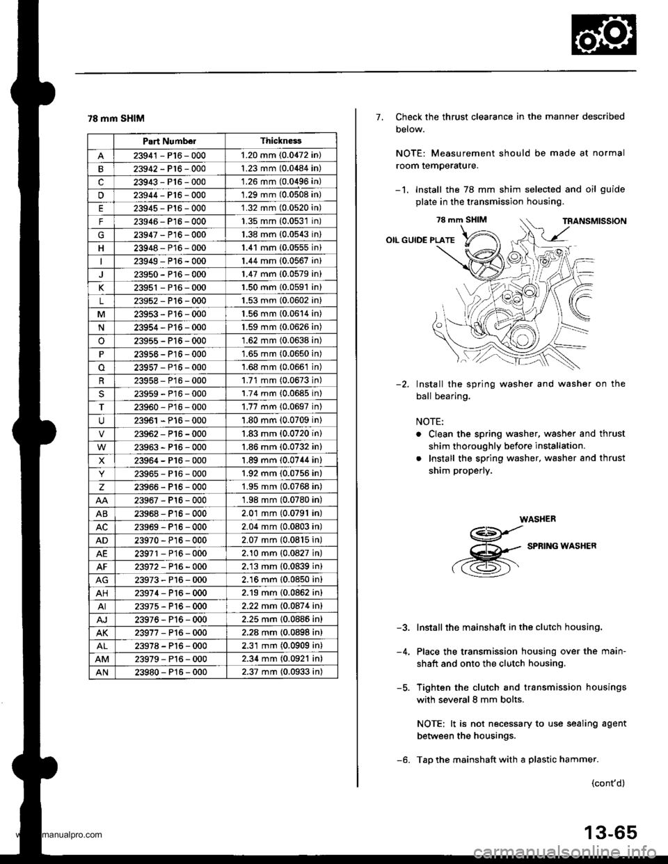
78 mm SHIM
Part NumborThickness
23941 - P16 - 0001.20 mm (0.0472 in)
23942-P16-0001.23 mm (0.0484 in)
c23943-P16-000'1.26 mm (0.0496 in)
u23944-Pt6-0001.29 mm (0.0508 in)
23945-P16-0001.32 mm (0.0520n)
F23946- P16 - 0001.35 mm (0.0531n)
G23947-P16-0001.38 mm {0.0543n)
H23948-P16-0001.41 mm (0.0555n)
23949-P16-0001.44 mm (0.0567 in)
23950-P16-0001.47 mm (0.0579 in)
K23951 - P16 - 0001.50 mm {0.0591 in}
L23952-Pl6-0001.53 mm (0.0602 in)
M23953-P16-0001.56 mm (0.0614 in)
N23954-P16-0001.59 mm (0.0626 in)
o23955-P15-0001.62 mm (0.0638 in)
23956 - P16 - 0001.65 mm (0.0650 in)
23957-P16-0001.68 mm (0.066't in)
23958- P16 - 0001.71 mm (0.0673 in)
23959-P16-0001.74 mm {0.0685 in)
T23960-P16-0001.77 mm {0.0697 inl
23961 - P16 - 0001.80 mm (0.0709 in)
23962-P16-0001.83 mm (0.0720 in)
23963-P16-000'1.86 mm (0.0732 in)
X23964-P16-0001.89 mm (0.0744 in)
23965-P16-0001.92 mm (0.0756 in)
z23966-Pl6-0001.95 mm (0.0768 in)
23967-Pl6-0001.98 mm (0.0780 in)
AB23968-P16-0002.01 mm (0.0791 in)
23969-Pl6-0002.04 mm (0.0803 in)
AD23970 - Pl6-0002.07 mm {0.0815 in)
AE23971 - P16 - 0002.10 mm {0.0827 in}
23972-P16-0002.13 mm (0.0839 in)
23973-P16-0002.16 mm (0.0850 in)
AH23974-P16-0002.19 mm (0.0862 in)
AI23975-P16-0002.22 mm 10.087 4 inl
AJ23976-Pl6-0002.25 mm {0.0886 in}
AK23977-P16-0002.28 mm {0.0898 in)
23978-Pl6-0002.31 mm (0.0909 in)
23979-Pl6-0002.34 mm (0.0921 in)
AN23980-P16-0002.37 mm (0.0933 in)
7, Check the thrust clearance in the manner described
Delow.
NOTE: Measurement should be made at normal
room temperature.
-1. Install the 78 mm shim selected and oil guide
plate in the transmission housing.
78 mm SHIM
OIL GUIDE PLATE
Install the spring washer and washer on the
ball bearing.
NOTE:
. Clean the spring washer, washer and thrust
shim thoroughly before installation.
. Install the spring washer, washer and thrust
shim properly.
WASHER
g
,-g
SPRTNG*ASHER
Install the mainshaft in the clutch housing.
Place the transmission housing over the main-
shaft and onto the clutch housing.
Tighten the clutch and transmission housings
with several 8 mm bolts.
NOTE: lt is not necessary to use sealing agent
between the housings.
Tap the mainshaft with a plastic hammer.
-2.
-5.
(cont'd)
13-65
www.emanualpro.com