Scan HONDA CR-V 1997 RD1-RD3 / 1.G Repair Manual
[x] Cancel search | Manufacturer: HONDA, Model Year: 1997, Model line: CR-V, Model: HONDA CR-V 1997 RD1-RD3 / 1.GPages: 1395, PDF Size: 35.62 MB
Page 354 of 1395
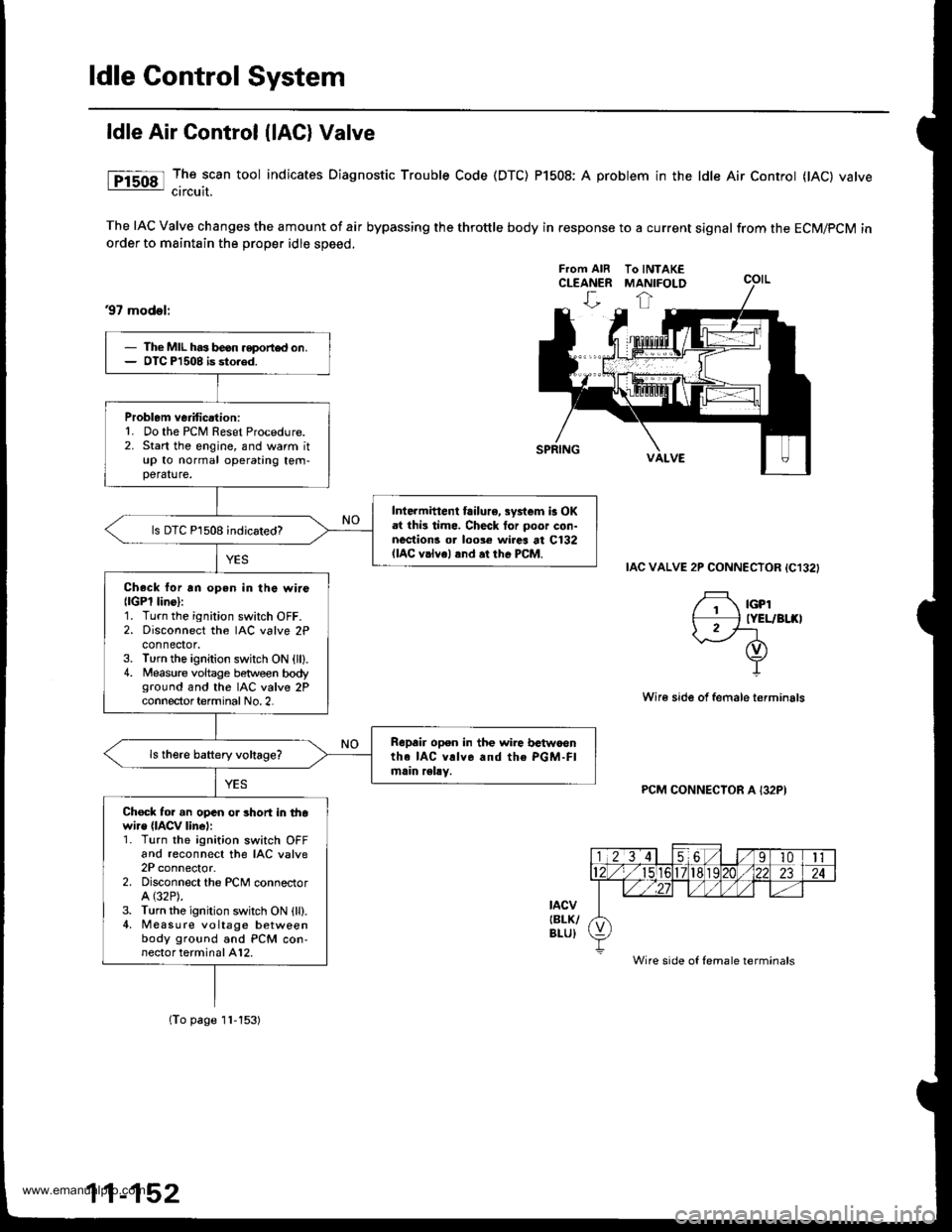
ldle Control System
ldle Air Control llAC) Valve
The scan tool indicates Diagnostic Trouble Code (DTC) Pl508: A probtem in the ldle Air Controt flAC) varvecircuit.
The IAC Valve changes the amount of air bypassing the throttle body in response to a current signal from the ECM/PCM inorder to maintain the proper idle speed.
37 model;
IAC VALVE 2P CONNECTOR {C132}
,f rcp'# IYEL/BI.(II2f-1-d)
Y
Wir€ side of female terminals
PCM CONNECTOR A I32PI
tacvIBLK/BLU)
From AIR To INTAKECLEANER MANIFOLD
Wire side of female terminals
The MIL has beon .eport€d on.OIC Pl508 is sto.ed.
Problem veiification:1. Do the PCM Reset Procedure.2. Start the engine, and warm itup to normal operating tem-perature.
Inte.mittent failure, systcm b OKat thi3 time. Check tor poo. con-nections or loose wircs at C132(lAC v.lvel and at the PCM.
ls DTC Pl508 indicated?
Check lor an open in the wir6{lGPl lins}:1. Turn the ignition switch OFF.2. Disconnect the IAC valve 2Pconnector.3. Turn the ignition switch ON {ll).4. Measure voltage between bodyground and the IAC valve 2Pconnector term inal No.2.
Repair open in the wire trctwoontha IAC v!lv6 and the PGM-Flmain relly.
Chock for an opan o. short in thowi.e (lACv linel:1. Turn the ignition switch OFFand reconnect the IAC valve2P connector.2. Disconnect the PCM conneclorA (32P).
3. Turn the ignition switch ON {ll).4, Measure voltage betweenbody ground and PCM con-nector terminal A12.
{To page 1l-153)
www.emanualpro.com
Page 402 of 1395
Emission Control System
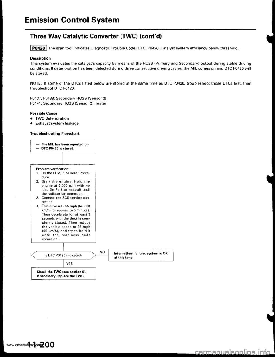
Three Way Catalytic Converter {TWCI (cont'd}
1P0420 Thescantool indicates Diagnostic Trouble Code (DTC) P0420: Catalyst system efficiency belowthreshold.
DescriDtion
This system evaluates the catalyst's capacity by means of the HO2S (Primary and Secondary) output during stable driving
conditions. lf deterioration has been detected during three consecutive driving cycles, the MIL comes on and DTC P0420 will
be stored.
NOTE: lf some of the DTCS listed below are stored at the same time as DTC P0420, troubleshoot those DTCS first. then
troubleshoot DTC P0420.
P0137, P0138: Secondary HO2S (Sensor 2)
P0141: Secondary HO2S (Sensor 2) Heater
Possible Cause
. IWC Deterioration
. Exhaust system leakage
Troubleshooting Flowchart
- The MIL has been reDoried on.- DTC P0420 is stored.
Problem verification:1. Do the ECM/PCM Reset Procedure,2. Start the engine. Hold theengine at 3,000 rpm with noload (in Park or neutrali untilthe radiator fan comes on.3. Connect the SCS service connector.4. Test-drive 40 - 55 mph (64 - 88km/h) for approx. lwo minutes.Then decelerate for at least 3seconds with the throftle completely closed. Then reducethe vehicle speed to 35 mph
156 km/h), and try to hold ituntil the readiness code
Intermittent tailure. system is OKat this time.ls DTC P0420 indicated?
Check the TWC (see section 9).lI nocessary, replace the TwC.
11-200
www.emanualpro.com
Page 407 of 1395

'97 model:
The scan tool indicates Diagnostic Trouble Code (DTC) P0441: Evaporative Emission (EVAP) control system
insufficient purge flow.
Description
By monitoring the purge line vacuum with the MAP sensor, the PCM can detect insufficient EVAP control system purge
flow.
Possiblo Cause
. EVAP Purge Control Solenoid Valve
. EVAP Purge Control Solenoid Valve Circuit
. EVAP Control Canister
. Vacuum Lines
. PCM
Troubleshooting Flowchart
EVAP PURGE CONTROL
SO1TNOID VALVE 2P
CoNNECTOR (C108)
(v)
YL
Wire side of female
termrnals
(cont'd)
11-205
Th€ MIL has b€en reooited on.DTC P0441 is .tored.
Problem verificationl1. Start the engine. Hold theengine at 3,000 rpm with noload (in Park or neut.al) untilthe radiator fan comes on.2. Do the PCM Reset Procedure.3. Connect the SCS service con-nector,4. Test drive under following con'ditions on the road.- without any electrical load- Transmission in @ or @position- Engine speed between1 ,2OO - 2,4OO rpfi.- Decelerate from 50 mph (80
km/h)to 15 mph (24 km/h)Intermittent trilure, sydern is OKat this time. Check for Door con-nections or loose wir€3 at C108
IEVAP purge control solonoidvalvol .nd at the PCM.
ls DTC P0441 indicated?
Check tor an open in the wire (lcl
linel:1. Turn the ignition switch OFF.2. Disconnect the EVAP purge
control solenoid valve 2P con-nector.3. Turn the ignition switch ON (ll).
4. Measure voltage between bodyground and the EVAP purge
control solenoid valve 2P con-nector terminal No. '1,
R€pafu open in thc wir6 b€tw€enthG EVAP purge control solenoidvalve and the No. 15 ALTEBNA-TOR SP SENSOR (7.5 A)fuse.
ls there batlery voltage?
(To page 11'206)
www.emanualpro.com
Page 410 of 1395
Emission Control System
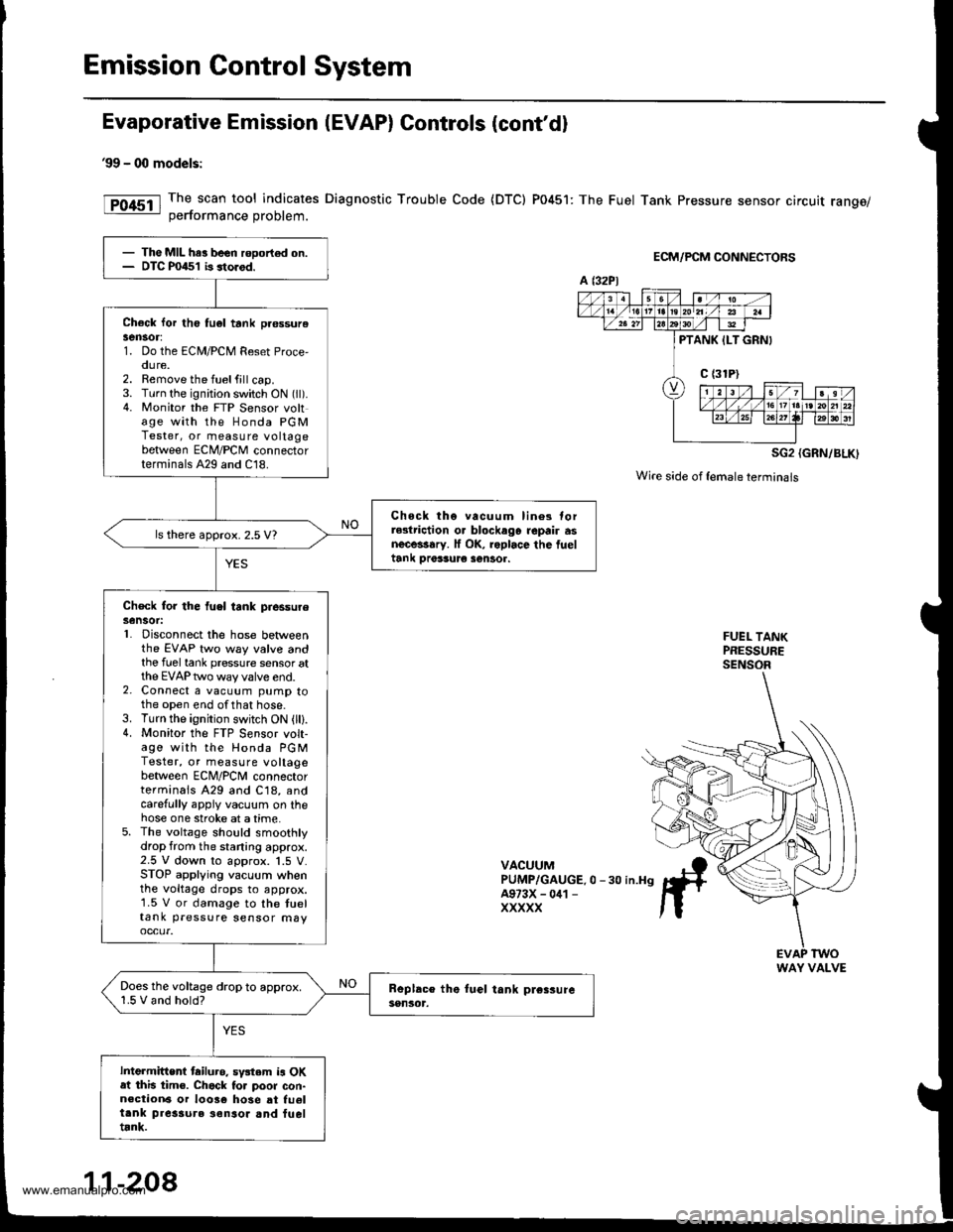
Evaporative Emission (EVAP) Controls (cont'd)
99 - 00 models:
The scan tool indicates Diagnostic Trouble Code {DTC) P0451: The Fuel Tank Pressure sensor circuit range/oerformance Droblem.
ECM/PCM CONNECTORS
SG2 {GRN/BLK)
Wire side of {emaleterminals
FUEL TANKPRESSURESENSOR
VACUUMPUMP/GAUGE.0 -30 in.H9A973X - 041 -
XXXXX
- The MIL har been rooort€d on.- DTC P0451 b storod.
Check lor th6 tu6l tank pr€ssurelen30r:1. Do the ECM/PCM Reset Proce,oure.2. Remove the fuelfill cap.3. Turn the ignition switch ON (ll).4. Monitor the FTP Sensor voltage with the Honda PGMTester, or measure voltagebetween ECM/PCM connectorterminals A29 and C18.
Chock tho vacuum lin6s torrGlriction o. blockago repair asnecessary. lf OK, roplace the fueltank Drer3ur€ sentor.
ls there approx. 2.5 V?
Check for the fuel tank piessureSensot:L Disconnect the hose betweenthe EVAP two way valve andthe fuel tank pressure sensor atthe EVAP two way valve end.2. Connect a vacuum pump tothe open end ofthat hose.3. Turn the ignition switch ON (lll.4. Monitor the FTP S€nsor volt-age with the Honda PGMTester, or measure voltagebetween ECNI/PCNI connectorterminals A29 and C18, andcarefully appiy vacuum on thehose one stroke at a time.5. The voltage should smoothlydrop from the staning approx.2.5 V down to approx. 1.5 V.STOP applying vacuum whenthe voltage drops to approx.1.5 V or damage to the tueltank pressure sensor may
Does the voltage drop to approx.1.5 V and hold?
Intermittent tailuro. sv3tem is OKat this tim€. Chack to. poor con-n€ction6 or 10036 hose at fu6ltank pres3ure ionsor and fueltrnk.
a t32Pl
PTANK ILT GRNI
WAY VALVE
11-208
www.emanualpro.com
Page 411 of 1395
'98 - 00 mod€ls:
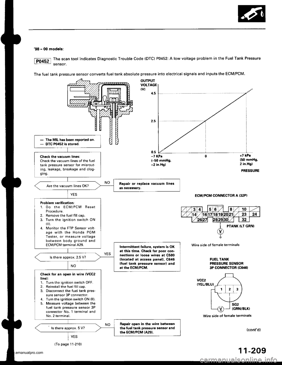
The scan tool indicates Diagnostic Trouble Code (DTC) P0452: A low voltage problem in the Fuel Tank Pressure
sensof.
The fuel tank Dressure sensor converts fuel tank absolute pressure into electrical signals and inputs the ECM/PCM.
OUTPUTVOLTAGEtvl{.5
0,5-? KPA(-50 mmHg,-2 in.Hgl
+7 kPr
l5O mmHg,2 in.Hgl
PRESSURE
ECM/PCM CONNECTOR A (32P)
Wire side ot female terminals
FUEL TANKPRESSURE SENSOR3P CONNECTOR tc6a6l
voc2(YEL/BLUI
Wire side ol fsmale terminals
(cont'd)
11-209
Th. MIL has been reoorted on.DTC m452 is stored.
Check the vacuum lin6:Check the vacuum lines of the fueltank pressure sensor for misrouting, leakage, breakage and clog-ging.
Are the vacuum lines OK?
Problem veriticstion:1. Do the ECM/PCM ResetProcedure-2. Remove the luelfillcap.3. Turn the ignition switch ONfl r).4. Monitor the FTP Sensor volt'age with the Honda PGMTester, or measure voltagebetween body ground andECM/PCM terminalA29.Intermittent failuro, system is OKat this lima. Chack lor Door con-nections or loose wi.es at C580llocrted rt access panell, C646lluel tank Daessure sensor) andat the ECM/PCM.
ls lhere approx. 2.5 V?
Check lor an open in wir€ lVeC2line):1. Turn the ignition switch OFF.2. Reinstallthe fuel fill cap.3. Disconnect the fuel tank pres-
sure sensor 3P connector,4. Turn the ignition switch ON (ll).
5- Measure voltage between thefLrel tank pressure sensor 3Pconnector No. 1 terminal andNo.2 terminal.
Replir opon in the wire b€tw€enth6 tuel tank pressure lensot andthe ECM/PCM {A29).ls there approx. 5 V?
YES
(To page 11-210)
www.emanualpro.com
Page 413 of 1395
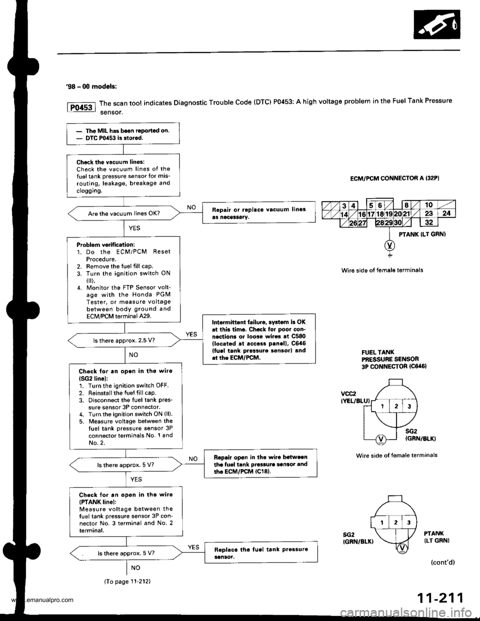
'98 - 00 modals:
The scan tool indicates Diagnostic Trouble Code (DTC) P0453: A high voltage problem in the Fuel Tank Pressure
sensor.
ECM/PCM CONNECTOR A {32PI
Wire sido ot fema16 t€rminals
FUEL TANXPf,ESSUBE SENSOR3p CONNECTOR {C6,a6l
vcc2IYEL/BLUI
sG2IGRN/BLKI
sG2(GRN/BLK}
Wire side ot female terminals
PTANKILT GRNI
(cont'd)
11-211
PTANK ILT GRN)
123
Thc MIL has b6on ropottcd on.DTC mia53 is dorcd.
Ch6ck tho vacuum linos:Check the vacuum lines of the
fuel tank pressure sensor lor mis-
routing, leakage, breakage and
cloggrng.
Are the vacuum lines OK?
Problorn verif ication:1. Do the ECM/PCM ResetProcedute.2. Remove the fuel fill cap.
3. Turn the ignition switch ON
{[).4. Monitor the FTP Sensor volt-age with the Honda PGM
Tester, or measure voltagebetween body ground and
ECM,PCM terminal429.Intarmittent tailuro, sv3iom b OKat this timo. Chock for poor con-nection3 or loo$ wire3 at C580(locstod .t .cc$r p.nell, C6a6(fucl tank pros3ure son3orl and.t the ECM/FCM.
ls there approx. 2.5 V?
Check lor an open in tho wiro
lSG2lin6l:1. Turn the ignition switch OFF.
2. R6installthe Iuel fill cap.3. Disconnect the Iu6l tank pres_
sure sensor 3P connector,4. Turn the ignition switch ON (ll).
5. M€asure voltago between thetuel tank pressure sensor 3P
connector terminals No. '! andNo.2.
Replir op€n in th. wi.c b€{weentha fuel tank Dio'sute sansot andtho EC|,/PCM {Cl8}.ls there approx. 5 V?
Ch€ck for an opon in tho wiro(PTANK linel:Measure voltage between thefuel tank pressure sensor 3P con-nector No. 3 terminal and No. 2terminal.
ls there approx. 5 V?
\To page 11-212)
www.emanualpro.com
Page 415 of 1395
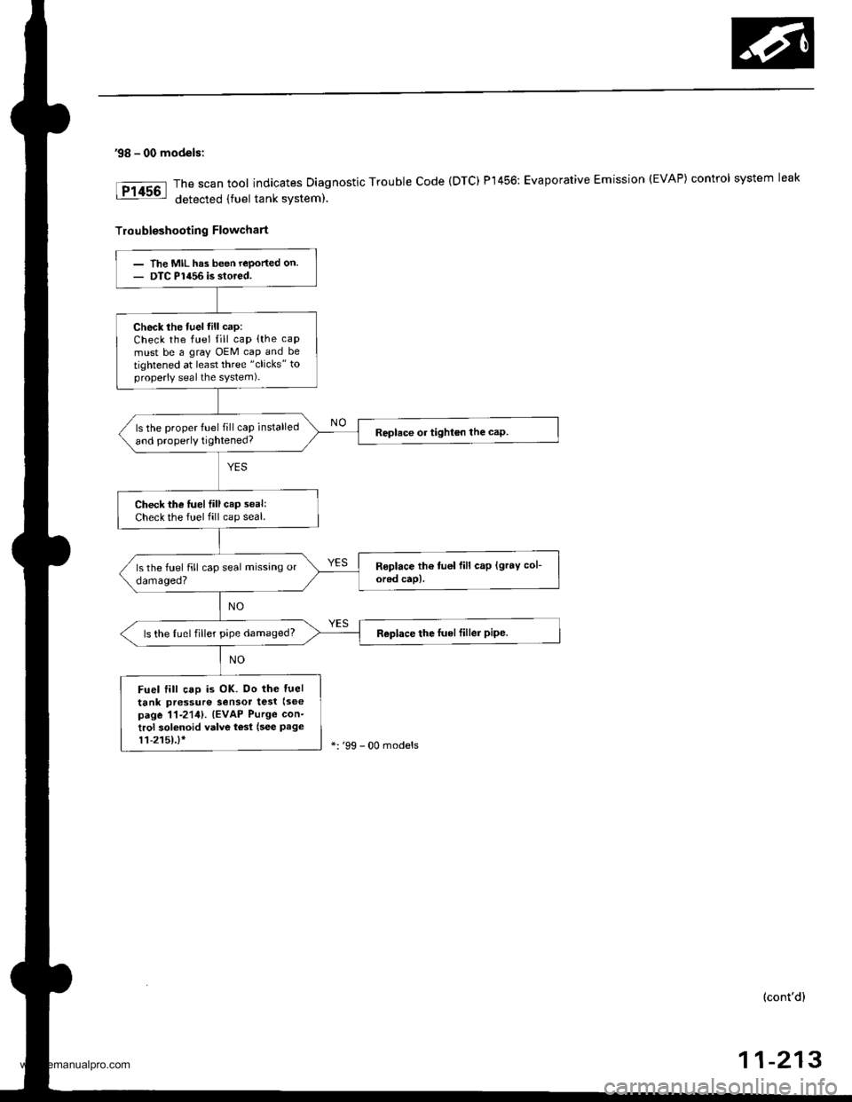
'98 - 00 models:
The scan tool indicates Diagnostic Trouble code (DTC) P1456: Evaporative Emission (EVAP) control system leak
detected {fuel tank system).
Troubleshooting Flowchart
- The MIL has been reported on.- DTC P1456 is stored.
Check the fuel fill cap:Check the fuel fill cap (the caP
must be a gray OEM cap and be
tightened at least three "clicks" toproperly seal the system)-
ls the proper fuel fill cap installed
and properly tightened?Replace or tighton the cap.
Check the lueltill cap seal:
Check the fuel fill cap seal.
Replace the luelfiller pipe.ls the tuel filler pipe damaged?
Fuel till caD is OK. Do the luel
tank pressure Sensor test (see
page 11-2111. (EVAP Purge con-
trol solenoid valve t€sl (see Page11-2151.1r':'99 - 00 models
(cont'd)
11-213
www.emanualpro.com
Page 421 of 1395
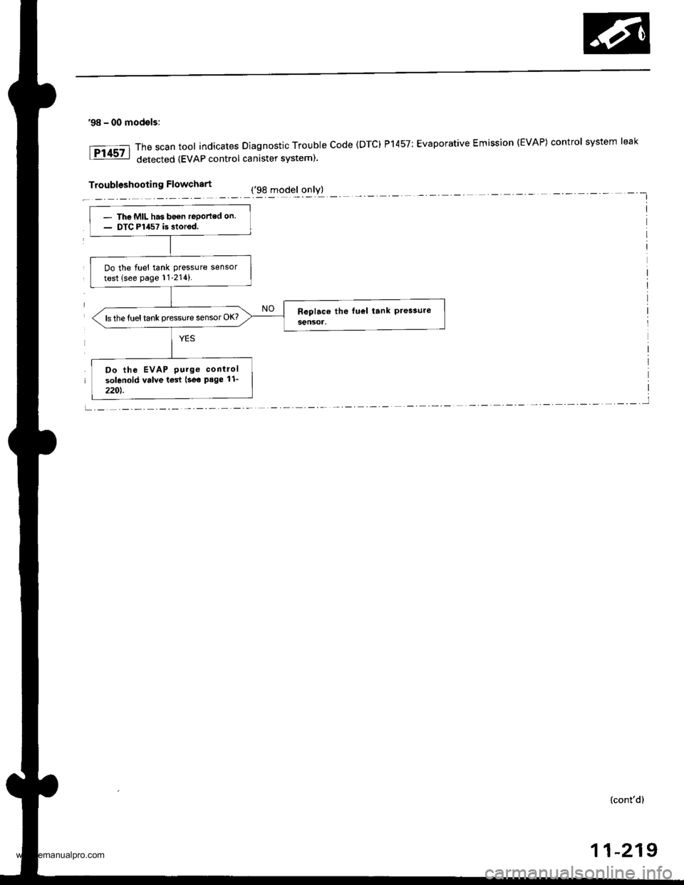
'98 - 00 mod€ls:
The scan tool indicates Diagnostic Trouble code (DTc) P1457: Evaporative Emission (EVAP) Control system leak
detected (EVAP control canister system).
Troubl6shooting Flowchart('98 model only)_]
I
- The MIL has been rePorted on.- DTC P1,157 is storod.
Do the fuel tank Pressure sensor
test {see page 11-214).
ls the {ueltank pressure sensor OK?
Do the EVAP Purge contlol
solenoid valve test lsea Page 1l_
220t.
(cont'dl
11-219
www.emanualpro.com
Page 572 of 1395
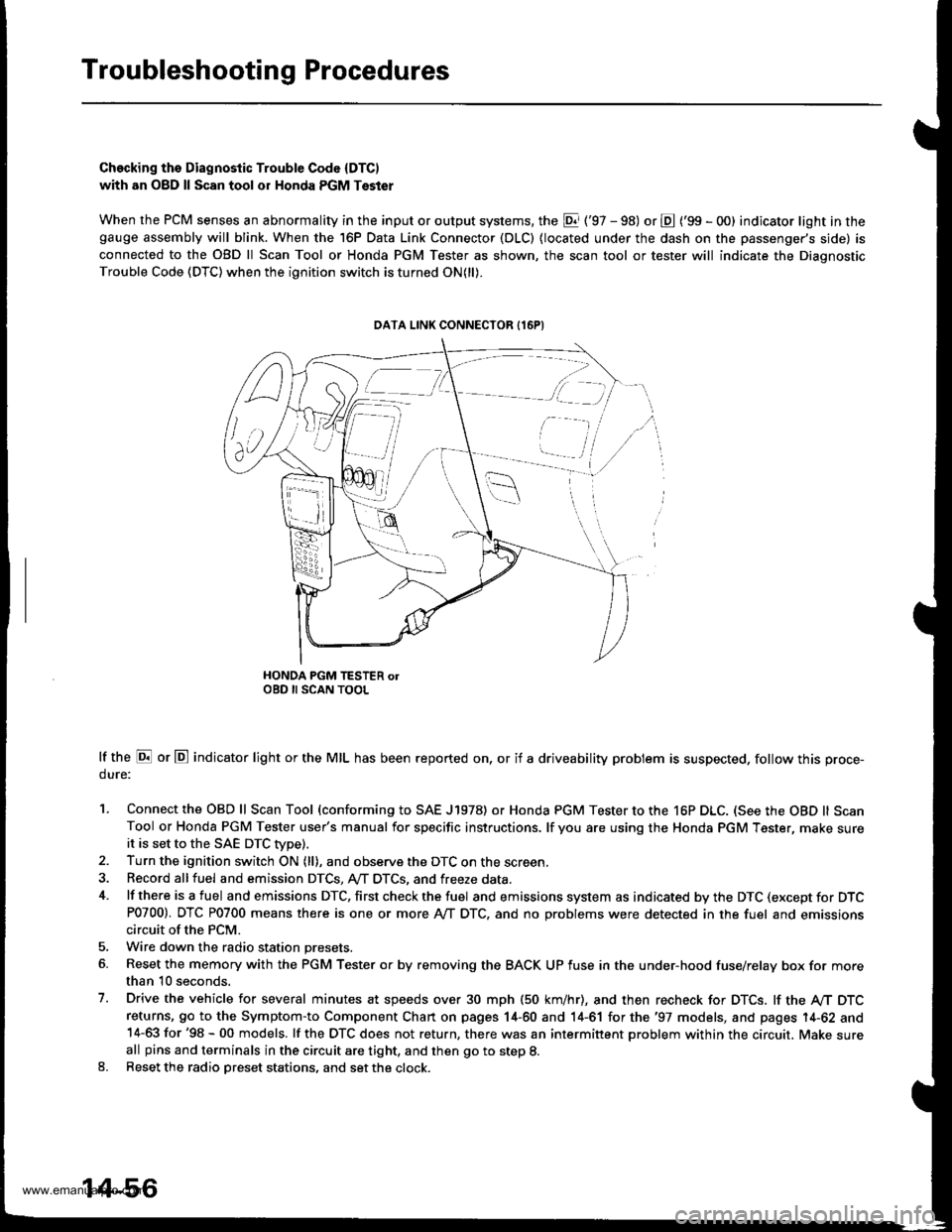
Troubleshooting Procedures
Checking ths Diagnostic Trouble Code (DTC)
with an O8D ll Scan tool or Honda PGM Tsster
When the PCM senses an abnormality in the input or output systems, the El ('97 - 98) or E ('99 - O0) indicator light in thegauge ass€mbly will blink. When the 16P Data Link Connector (DLC) {located under the dash on the passenger's side) is
connected to the OBD ll Scan Tool or Honda PGM Tester as shown, the scan tool or tester will indicate the Diagnostic
Trouble Code (DTC) when the ignition switch is turned ON(ll).
HONDA PGM TESTER olOBD II SCAN TOOL
lf the E or E indicator light or the MIL has been reported on, or if a driveability problem is suspected, follow this proce-
dure:
1. Connect the OBD ll Scan Tool (conforming to SAE J1978) or Honda PGM Tester to the 16P DLC. (See the OBD ll ScanTool or Honda PGM Tester user's manual for specific instructions. lf you are using the Honda PGM Tester, make sureit is set to the SAE DTC Wpe).2. Turn the ignition switch ON (ll), and observe the DTC on the screen
3. Record allfuel and emission DTCS, A,,/T DTCS, and freeze data.
4. lf there is a fuel and emissions DTC, first check the fuel and emissions system as indicated by the DTC (except for DTCP0700). DTC P0700 means there is one or more Ay'T DTC, and no Droblems were detected in the fuel and emissionscircuit of the PCM.
5. Wire down the radio station presets.
6. Reset the memory with the PGM Tester o. by removing the BACK UP fuse in the under-hood fuse/relay box for morethan 10 seconds.
7. Drive the vehicle for several minutes at speeds over 30 mph (50 km/hr), and then recheck for DTCS. lf the A/T DTCreturns, 9o to the Symptom-to Component Chart on pages 14-60 and 14-61 for the '97 models, and pages 14-62 and14-63 for '98 - 00 models. lf the OTC does not return, there was an intermittent problem within the circuit. Make sureall pins and terminals in the circuit are tight, and then go to step 8.8. Reset the radio Dreset stations, and set the clock.
DATA LINK CONNECTOR {16PI
[ -=.r,
ili,i /i,
v,., i
14-56
www.emanualpro.com
Page 575 of 1395
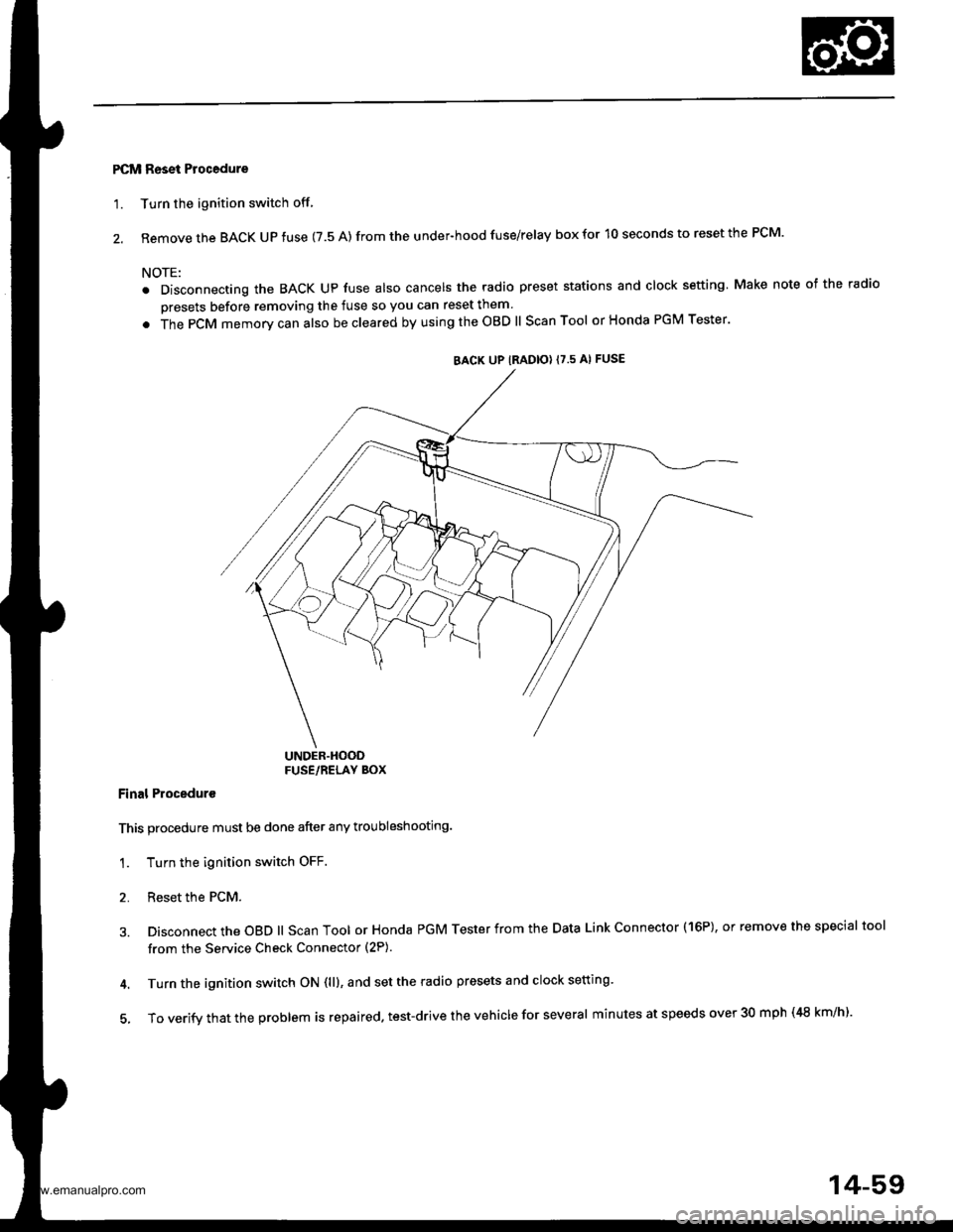
PCM Reset Procedure
'1. Turn the ignition switch off
2. Remove the BACK UP fuse (7.5 A) from the under-hood fuse/relay box for 10 seconds to reset the PCM.
NOTE:
. Disconnecting the BACK Up fuse also cancels the radio preset stations and clock setting Make note of the radio
presets before removing the fuse so you can reset them
. The PCM memorv can also be cleared by using the OBD ll Scan Tool or Honda PGM Tester'
UNDER.HOODFUSE/RELAY BOX
Final Proceduro
This procedure must be done after any troubleshooting.
1. Turn the ignition switch OFF.
2. Reset the PCM.
3. Disconnect the OBD ll Scan Tool or Honda PGM Tester from the Data Link Connector (16P), or remove the special tool
from the Service Check Connector (2P).
4. Turn the ignition switch ON (ll), and set the radio presets and clock setting'
5, To verify that the problem is repaired. test-drive the vehicle for several minutes at speeds over 30 mph (48 km/h).
BACK UP IRADIO} {7.5 AI FUSE
14-59
www.emanualpro.com