Brake line HONDA CR-V 1997 RD1-RD3 / 1.G Workshop Manual
[x] Cancel search | Manufacturer: HONDA, Model Year: 1997, Model line: CR-V, Model: HONDA CR-V 1997 RD1-RD3 / 1.GPages: 1395, PDF Size: 35.62 MB
Page 34 of 1395
2-9
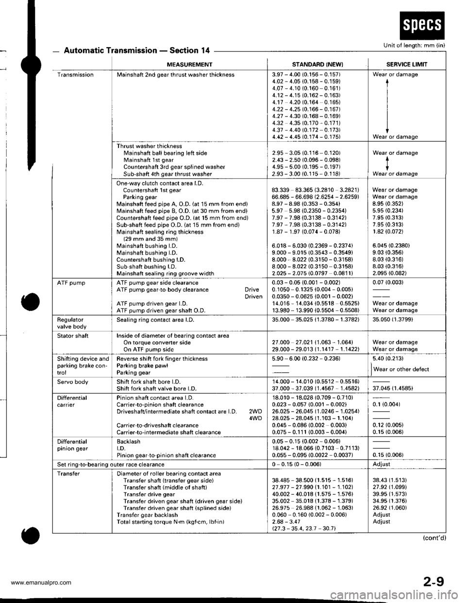
Automatic Transmission - Section 14
o
Unit of length: mm (in)
o
MEASUREMENTSTANDARD (NEWISERVICE LIMIT
TransmissionMainshaft 2nd gear thrust washer thickness3.97 - 4.00 10.156 - 0.157)4.02 - 4.05 {0.158 - 0.159)4.07 - 4.1010.160 0.161)4.12 - 4.15 (0.162 - 0.163)4.17 4.20 (0.164 0.165)4.22 - 4.25 10.166 - 0.167 )4.27 - 4.30 (0.168 - 0.169)4.32 4.35 (0.170-0.171)
4.37 - 4.40 (0.172 0.173)4.42 - 4.45 (0.174 - 0. r75)
I
I
IWear or damage
Thrust washer thicknessl'rainshaft ball bearing left sideMainshaft 1st gear
Countershaft 3rd gear splined washerSub-shaft 4th gear thrust washer
2.95 3.05 (0.116 0.120)2.43 - 2.50 (0.096 - 0.098)4.9s - 5.00 (0.195 - 0.197)2.93 - 3.00 (0.115 - 0.1181
Wear or damage
tIWear or damage
One-way clutch contact area LD.Countershaft 1st gearParking gearMainshaft feed pipe A, O.D. (at 15 mm trom end)Mainshaft feed pipe B, O.D. (at 30 mm from end)Countershaft teed pipe O.D. lat 15 mm from end)Sub-shaft feed pipe O.D. (at 15 mm from end)Mainshatt sealing ring thickness(29 mm and 35 mm)Mainshaft bushing I.D.Mainshaft bushing l.D.Countershaft bushing l.D.Sub shatt bushing LD.Mainshaft sealing ring groove width
83.339 83.365 (3.2810 3.2821)66.685 - 66.698 (2.6254 - 2.6259)8.97 - 8.98 (0.353 - 0.354)5.97 5.98 {0.2350 - 0.2354)7.97 - 7.98 (0.3138 - 0.3142)7.97 ,7.98 (0.3138 - 0.3142)1.87 - 1.97 (0.074-0.078)
6.018 - 6.030 (0.2369 - 0.2374)9.000 - 9.015 (0.3543 - 0.3549)8.000 - 8.022 (0.3150-0.3158)
8.000 - 8.022 (0.3150 0.3158)2.025 - 2.075 (0.0797 0.0811)
Wear or damageWear or damage8.95 (0.352)
5.95 (0.234)
7.95 (0.313)
7.95 {0.313)1 .42 $.O72)
5.045 (0.2380)
9.03 (0.356)
8.03 (0.316)
8.03 (0.316)
2.095 (0.082)
ATF pumpATF pump gear side clearanceATF pump gear'to body clearance DriveDrivenATF pump driven gear LD.ATF pump driven gear shaft O.D.
0.03 - 0.05 (0.001 - 0.002)0.1050 0.1325 (0.004, 0.005)0.0350 - 0.0625 10.001 - 0.002)14.016* 14.034 (0.5518 0.5525)13.980 - 13.990 {0.5504 0.5508)
0.0710.003)
Wear or damageWear or damage
Regulatorvalve bodySealing ring contact area l.D,35.000 35.025 {1.3780 - 1.3782)35.050 (1.3799)
Stator shaftInside of diameter oI bearing contact areaOn torque convener sideOn ATF pump side2't .o00 27 .021 I '1 .063 , 1 .064)29.000 - 29.01311.r417 1.1422)Wear or damageWear or damage
Shifting device andparking brake con'trol
Reverse shitt fork finger thicknessParking brake pawl
Parking gear
5.90 - 6.00 {0.232,0.236)5.40 (0.213)
lWear or other defect
Servo bodyShift fork shatt bore l.D.Shift fork shatt valve bore l.D.14.000 - 14.010 (0.55'�l2 - 0.5516)37.000 - 37.039 (1.4567 - 1.4582)37.045 (1.4585)
DifferentialcarrierPinion shaft contact area LD.Carrierto-pinion shaft clearanceDriveshafvintermediate shaft contact are l.D. 2WD4WDCarrier to driveshalt clearanceCarrier-to-intermediate shaft clearance
'18.010 - 18.028 10.709 - 0.710)0.023 - 0.057 {0.001 - 0.002}26.025 - 26.045 (1.0246 - 1.0254)28.025 - 28.045 (1.103 - 1.104)0.045 - 0.08610.002 0.003)0.075 - 0.111 10.003- 0.004)
0.r {0.004)
0.12 (0.005)
0.15 (0.006)
Differentialprnron gearBacklasht.D.Pinion gear'to-pinion shaft clearance
0.05 - 0.15 (0.002 - 0.006)18.062 - 18.066 (0.7103 - 0.7113)0.055 - 0.095 10.0022 - 0.0037)otu to.oout
Set ring-to-bearing outer race clearance0 0.15 (0 - 0.006)Adjust
TransferDiameter of roller bearing contact areaTransfer shaft (transfer gear side)Transfer shaft (middle of shaft)Transfer drive gearTransfer driven gear shaft {driven gear side)Transfer driven gear shaft {splined side)Transfer gear backlashTotalstarting torque N.m (kgf.cm, lbf.in)
38.485 38.500 (1.515 - 1.516)27 .917 - 21 .990 |.1.101 - 1.102)40.002 - 40.018 (1.575 - 1.576)35.002 35.018 (1.378 - 1.379)26.975 26.988 (1.062 -'�l.063)
0.060 0.160 (0.002 - 0.006)2.64 - 3.41127.3 - 35.4,23.1 30.71
38.43 (1.513)
27.92 (1.099)
39.95 (1.573)
34.95 (1.376)
26.92 (1.060)
AdiustAdiust
(cont'd)
www.emanualpro.com
Page 36 of 1395
to
l
SuspensionSection 18
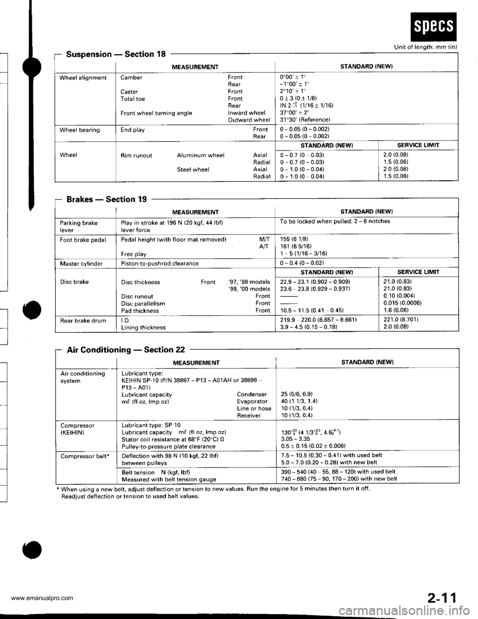
BrakesSec'tion 19
Air ConditioningSection 22
* When using a new belt, adjust deflection or tension to new values. Run the engine for 5 minutes then turn it off.
Readjust deflection or tension to used belt values.
o
Unit of length: mm {in)
MEASUREMENTSTANDARD {NEW)
WheelalignmentCamber FrontRearCaster FrontTotaltoe FrontnearFront wheel turning angle Inward wheelOutward wheel
0"00' 1 1'- 1"00' 1 1'2"10' ! 1"0J3(011/8)rN 2 ri (1/161 1/r6)37"00' ! 231'30'(Referencei
Wheel bearingEnd playFrontRear0 - 0.05 {0- 0.002}0 - 0.05 (0 0.002i
Rim runout Aluminum wheel AxialBadialSteelwheel AxialRadial
STANOARD (NEW)SERVICE LIMIT
0 - 0.7 (0 0.03)0,0.7 (0 - 0.03)0 1.0 (0 - 0.04)0 - 1.0 {0 - 0.04)
2.0 (0.08)'r.5 {0.06)2.0 {0.08)1.s (0.06)
MEASUREMENTSTANDARD INEWI
Parking brakeleverPlay in stroke at 196 N (20 kgf,44lbf)lever force
To be locked when Dulled: 2 - 6 notches
Foot brake pedalPedal height (with tloor mat removed)
Free playNT
155 (6 1/8)161 (6 5/16)1 5 (1/16 - 3/16)
Master cylinderPiston-to-pushrod clearance0 - 0.4 (0- 0.02)
Disc brakeDisc thickness Front '97, '98 models'99, '00 modelsDisc runoutDisc parallelismPad thickness
FrontFrontFront
STANDARD {NEW'SERVICE LIMIT
22.9 - 23.1 (0.902 - 0.909)23.6 23.8 (0.929 - 0.937)
10.5 - 11.5 (0.4'�t 0.45)
21.0 (0.83)
21.0 (0.83)
0.10 {0.004)0.015 (0.0006)
1.6 (0.06)
Rear brake drumLD.Lining thickness
2r9.9 220.0 (8.657 - 8.661)3.9 - 4.5 (0.15 - 0.18)221.O 8.70112.0 (0.08)
MEASUREMENTSTANDARD {NEWI
Air conditioningLubricant type:KEIHIN SP 10 (P/N 38897 - Pl3 - A01AH or 38899 -
Pl3 - A01)Lubricant capacity Condensermf {floz, lmp oz) EvaporatorLine or hoseReceiver
25 (5/6,0.9)
40 {1 1/3, 1.4)10 {1/3,0.4)10(.]/3,0.4)
Compressor(KEIHIN)Lubricant type: SP 10Lubricant capacity ml ({l 02, lmp oz}Stator coil resistance at 68'F (20"C) OPulley-to-pressuae plate clearance
130'3'{4 1fi'3o, 4.6;"}3.05 - 3.350.51 0.15 (0.02 1 0.006)
Compressor belt*Deflection with 98 N (10 kgl,22lblibetween pulleys7.5 - 10.5 {0.30 - 0.41) with used belt5.0 - 7.0 (0.20 - 0.28) with new belt
Belt tension N (kgf, lbf)Measured with belt tension gauge390 - 540 (40 55,88-120)withusedbelt740 - 880 {75 90, 170 - 200) with new belt
2-11
www.emanualpro.com
Page 41 of 1395

Lubrication Points
For the details of lubrication points and type of lubricants to be applied. refer to the illustrated index and various work pro-
cedures (such as Assembly/Reassembly, Replacement, Overhaul, Installation, etc.) contained in each section.
Recomm6nded Engine OilEngine oil viscosity for ambient temperature ranges
100'F
-30 -20 .10 0 10 20 30 40'c
r1: Always use Genuine Honda Manual Transmission Fluid {MTF). Using motor oil can cause stiffer shifting because it
does not contain the orooer additives.*2: Always use Genuine Honda Premium Formula Automatic Transmission Fluid (ATF). Using a non-Honda ATF can affect
shift qualitv.+3r Always use Genuine Honda DOT 3 Brake Fluid. Using a non-Honda brake fluid can cause corrosion and decrease the
life of the system.*4: Always use Genuine Honda Power Steering Fluid. Using any other type of power steering fluid or automatic transmis-
sion fluid can caused increased wear and poor steering in cold weather.
API SERVICE LABEL
/,.*-G\
/.'z-\e\t/6AE\ll-;-1 5w-30 /---l
w
API CERTIFICATION SEAL
ffi-20 0 20
NO.LUBRICATION POINTSLUBRICANT
EngineAPI Service Grade: Use SJ "Energy Conserving" grade oil. The oilcontainer may also display the API Certitication seal shownbelow. Make sure it says "For Gasoline Engines." SAE vjscosity:See chart below.
2
TransmissionManualGenuine Honda MTF*1
AutomaticGenuine Honda Premium Formula Automatic Transmission Fluid(ATF)*'
3Rear differentialGenuine Honda CVT Fluid
4Brake line (includes ABS line)Genuine Honda DOT 3 Brake Fluid*3
5Clutch LineBrake fluid DOT 3 or DOT 4*3
6Shift lever pivots (Manual transmission)Grease with molybdenum disultide
1Release fork (Manual transmission)LJrea Grease UM264 P/N 4'1211 - PYs - 305
IPower steering gearboxSteering grease P/N 08733 - B070E
Throttle cable end {Dashboard lower panel holelSilicone grease
10l112
14
Throttle cable end (Throttle link)Brake master cylinder pushrodPedal linkageBattery terminalsFuelfill lidClutch master cylinder pushrod
Multi purpose grease
1617181920
Hood hinges and hood lockTailgate hingesHatch glass hingesDoor hinges, upper and lowerDoor opening detent
Honda White Lithium Grease
21
22
Caliper Piston seal, Dust seal,Caliper pin, PistonShilt cable and select cable {Manual transmission)Silicone grease
23Brake line ioints (Front and rear wheelhouse)Rust preventives
24Power steering systemGenuine Honda Power Steering Fluid-.
25Air conditioning compressorCompressor oil: SP 10 lP/N 38897 - P13 - A0lAH or38899-P13-A01)For Refrigerant: HFC 134a (R,134a)
3-2
www.emanualpro.com
Page 204 of 1395

Fuel and Emissions
Special Tools ...................... 11-2
Component Locations
lndex ...................... ....,.... 11-3
Svstem Description
Vacuum Connections ...........,....,.,................. 1 1-9
Electrical Connections ................................... 1 1-15
System Connectors .,.,,.,............................,.,. 1 1-36
Troubleshooting
Troubleshooting Procedures,.,..................... 11-60
Engine Control Module/Powertrain ConttolModule Terminal Arrangement .............., 11-67
Diagnostic Trouble Code Chart .................... 1 t-75
How to Read Flowcharts .......,.....,.,............... I 1-79
PGM-Fl System
System Description .................,.,.,,,............... 1 1-80
Troubleshooting Flowcharts
Engine Control Module/PowertrainControl Module ........11-52
Manifold Absolute Pressure Sensor ............. 11-90
Intake Air Temperature Sensor .................... 1 1-95
Engine Coolant Temperature Sensor .,..,.,.... 1 1-99
Throttle Position Sensor ...........,.....,.,.,..,...... I 1'103
Primary Heated Orygen Sensor (Sensor 1) ... 11-110
Secondary Heated Oxygen Sensor{Sensor 2l .................. 1 1-117
Heated Oxygen Sensor Heater ..................... 11-121
Fuef Supply System ......11-124
Random Misfire ,....,.,..... 11-126
Mistire Detected in One Cylinder .....-........... 11-128
Knock Sensor ................ 11-130
CKP/TDC/CYP Sensor .................................... 1 1-131
Vehicle Speed Sensor ...............................,.... 1 1-135
Barometric Pressure Sensor .....,...,...,.,,........ 1 1-137
Electrical Load Detector ...,.,.......................... 1 1-138
CKF Sensor ................,.,, '11-112
ECM/PCM lnternaf Circuit ............................. 11'117
HO2S Replacement .,.,.,. 11-148
ldle Control System
System Description ............ 11-149
Troubleshooting Flowcharts
ldle Control System ...... 11-150
fdle Air Control Valve ......................,............. 11-152
Air Conditioning Signal ................................. I 1-155
Alternator FR Signal ...................................... 1 1-159
Starter Switch Si9na1 .................................... t l-161
Power Steering Pressure Switch Signal ...... 11-162
Brake Switch Si9na1 ...................................... 11-166
Fast ldle Thermo Valve .,.,.............................,.,.,. 11-168
ldle speed setting .............. 11-169
Fuel Supply System
Fuel Lines ............................ 11-171
Fuef Tube/Ouick-Conneci Fittings ..................... 11 -175
System Description ............ 11-178
Fuel Pressurg ...................... 11-178
Fuel Iniectors ................,..... 11-179
Fuel Pressure Re9u1ator .............................,.,...., f 1-181
Fuef Fifter ....,.,.,.,,,,.,............11-142
Fuel Pump ........................... 11-183
Fuel Gauge .......................... 11-184
Fuel Gauge Sending Unit ................................... I 1-185
Low Fuel Indicator System ...........,.,..,............... 1 1-185
PGM-FI Main Relay ............. 11-187
Fue|Tank................ ............. 11-191
Intake Air System
System Description ............ 11-193
Air Cleanel ,.,.,..................... 11-194
Throttle Cable ..................... 11-194
Throttle Body........ .............. 11-196
Emission Control System
System D$cription ...,....,.,. 11-199
Tailpipe Emission ............... 11-199
Three Way Catalytic Converter ..................,.,...,, 11-199
Positive Crankcase Ventilation System .,.,,,,.,.., 11-2O1
Evaporative Emission Controls .........,.,.,............ 11-203
www.emanualpro.com
Page 273 of 1395

Engine/Powertrain Control Module Terminal Arrangement - 38 - 00 Models
ECM/PCM CONNECTOR A (32P}
,/./5aIsca
,/ l,/t5ItsTs
n2ls!uCI
Wire side ot female terminalsECM/FCM CONNECTOR A {32P)NOTE: Standard baftery voltage is '12 V.
D93criptionSignal
3BLU2WBS {EVAP BYPASSSOLENOID VALVE)Drives EVAP bvoass solonoid valve.With ignirion switch ON {ll)r battery voltage
LT GRNMHTVSV {EVAP CONTROL CANISTEB VENT SHUT VALVE)D.ives EVAP controlcanisler vent shutWith ig^ition switch ON (ll): battery voltage
5',BLUCRS (CRUISE CONTROL SIG'NAL)Shift Oown signalinputfrcm cruise conWhen cruise control is used: pulses
6RED/YEL
PCS (EVAP PURGE CONTROLSOLENOID VALVE)Drives EVAP purge controlsolonoid valve.With engins running, engine coolant, below 154'F(68'C)r battery voltageWith engine running, engine coolant, above 154"F{6a'C}r duty conl.olled
8ELIOWHTSO2SHTC (SECONDARVHEATED OXYGEN SENSORHEATER CONTROL)
Drives sacondary heated oxygen sensorWith ignition switch ON (ll): banery voltageWith fully warmed up engine running: duty
10BRNSCS (SERVICE CHECX SIGNAL)Detects seNics check conneclor signal(he signalcausing a DTC indicatjon)with rhe lerminal connected:0 vWith the rerminaldisconnectedrabout 5 v or
l4'rGRN/8LKD4IND (D4INDICATOR)+3DIND (D INDICATORTIDrives D4*3. Dr'indicaior light.W,rh 04' , O" indrcator light turned O batter,
With D4*3, D*. indicator light turned OFFr0 V
16GRNI/ELFLR (FUEL PUMP RELAY)Drivss fusl pump relay.0 V for iwo seconds after ru'nin9 ign'lion swilchON lll), then banery voltage
17AL|(/REDACC (I/C CLUTCH RELAY}Drives l,/C clurch rclay.With compressor ONr0 VWith compressor OFF: battery voltage
18GRN/ORNMIL (MALFUNCTION INDICA.TOR LIGHT)Driv€s MlL.With MlLturned ON:0 VWith MIL turned OFF: battery voltage
19BLUNEP (ENGINE SPEED PULSE)Outputs engine spsed pulse.With sngine runnin9: pulses
20GRNFANC {RADIATOR FAN CONTROL)Drives r6diator fan rslay.With radaator fan running:0 VWith radaatorfan stopped: battery vollage
218LU/t/ELK-LINESends and receiv€s scan toolsignal.With ignition switch ON (ll): p'rlses
23WHT/REDSHO2S (SECONDARY HEATEDOXYGEN SENSOR. SENSOR 2iDetects secondary h€at€d oxygen sensorWith throttle fully opened from idle wilh fullywalmed up engine: above 0.6 Vwith rhrottle quickly closed: below 0-4 V
21BLU/WHTSTS (STARTER SWITCH SIG,NAL}Dotocts srarter switch signal.Whh staner switch ON (lll): batlery voltageWith srarter switch OFF: 0 V
26GBNPSPSW {P/S PsESSUFESWITCH SIGNAL)Detecrs PSP switch signal.At idle with steeing wh€el in stBighl ahead position: 0 VAt idls with nee ng wheel al full lockr banory voltage
2fBLU/BEOACS (Ir'C SWTCH SIGNAL}D€tects ly'C switch signal.With Ay'C switch ON:0 VWith l/C swil€h OFF: about 5 V
2A'\WHT/NEDSLU {INTERLOCK CONTROLUNIT)Orives interlock control unil.With ignilion switch ON (ll)and brake pedaldepressed: battery vohage
29LT GRNPTANK (FUEL TANK PRES'SURE SENSOR)Detocts fueltank pressure sensor signal.With agnition switch ON (ll) and fuel fill capopensd; about 2.5 v
GBN/FEDEL (ELD}Detects ELD signal.Wirh paaing rightstumed on at idle:about 2.5 - 3.5 VWith low beam headlights tumed on at idle:about 1.5-2.5V
GRN/WHTBKSW (BRAKE SWTTCH)Dst€cts brake switch signal.Wirh brake pedal released:0 VWith brake pedal depressed: battery vollage
13: '98 modsl
15: USA(cont'd)
11-71
www.emanualpro.com
Page 282 of 1395

PGM-FI System
System Description
INPUTS
CKP/TDC/CYP Sensor
CKF Sensor
MAP Sensor
ECT Sensor
IAT Sensor
TP Sensor
Primary HO2S
Secondary H02S
vss
KS*5
BARO Sensor
ELD*6
Starter Signal
ALT FR Signal
Air Conditioning Signal
Ay'T Gear Position Signal*1
Baftery Voltage (lGN.1)
Brake Switch Signal
PSP Switch Signal
Fuel Tank Pressuae Sensor*4. *5
Countershaft Speed Sensor*1
Mainshaft Speed Sensor*r
OVER-DRIVE Switch Signal*s
ENGINE CONTROL MODULE (ECM)/
POWERTRAIN CONTROL MODULE (PCM) OUTPUTS
|iuel 1"j""- Th,rhg ""d Drrafr";-l
Et*-.nt"tdt"cont.orl
to,r*,c;;trffi;]
l.----.---:. .Lrgnrnon |lmrng Lonrror I
Ecir/PcM B*k',p Fr""il]
m;"t-ll-r*'io*l
Fuel Injectors
PGM-Fl Main Relay (Fuel Pump)
MIL
IAC Valve
Ay'C Compressor Clutch Relay
Radiator Fan Relay
Condenser Fan Relay
ALT
tcM
EVAP Purge Control Solenoid
Valve
Primary HO2S Heater
Secondary H02S HeaterEVAP Bypass Solenoid Valve*a *5
EVAP Control Canister Vent Shut
DLC
Lock-up Control Solenoid Valve*l
Shift Control Solenoid Valve*1
Ay'T Clutch Pressure Control
Solenoid Valve*1
D4 Indicator Light'1 *3, *a
D Indicator Light,l *5
OVER-DRIVE OFF Indicator
Lighl*t *:
*1: A/T {3:'97 model'2: M/f +4:'98 model*5: '99 - 00 models"6: USA
PGM-Fl System
The PGM-Fl system on this model is a sequential multiport fuel injection system.
Fuel iniecior Timing and Duration
The ECM/PCM contains memories for the basic discharge durations at various engine speeds and manifold pressure. The
basic discharge duration, after being read out from the memory, is further modified by signals sent from various sensors
to obtain the final discharge duration.
ldle Air Control
ldle Air Control Valve (lAC Valve)
When the engine is cold, the Ay'C compressor is on, the transmission is in gear, the brake pedal is depressed, the P/S load
is high, or the alternator is charging, the ECM/PCM controls current to the IAC Valve to maintain the correct idle speed.
lgnition Timing Control
o The ECM/PCM contains memories for basic ionition timing at various engine speeds and manifold air flow rates.
lgnition timing is also adjusted for engine coolant temperature.
. A knock control system was adopted which sets the ideal ig nition timing for the octane rating of the gasoline used.*s
Other Control Funstions
1. Starting Control
When the engine is started. the ECM/PCM provides a rich mixture by increasing fuel injector duration.
2. Fuel Pump Control
. When the ignition switch is initially turned on (ll). the ECMiPCM suppli€s ground to the PGM-FI main relay that
supplies current to the fuel pump for two seconds to pressurize the fuel system.
. When the engine is running, the ECM/PCM supplies ground to the PGM-FI main relay that supplies current to the
fuel oumo.
. When the engine is not running and the ignition is on, the ECM/PCM cuts ground to the PGM-FI main relay which
cuts current to the fuel pump.
1 1-80
www.emanualpro.com
Page 368 of 1395
ldle Control System
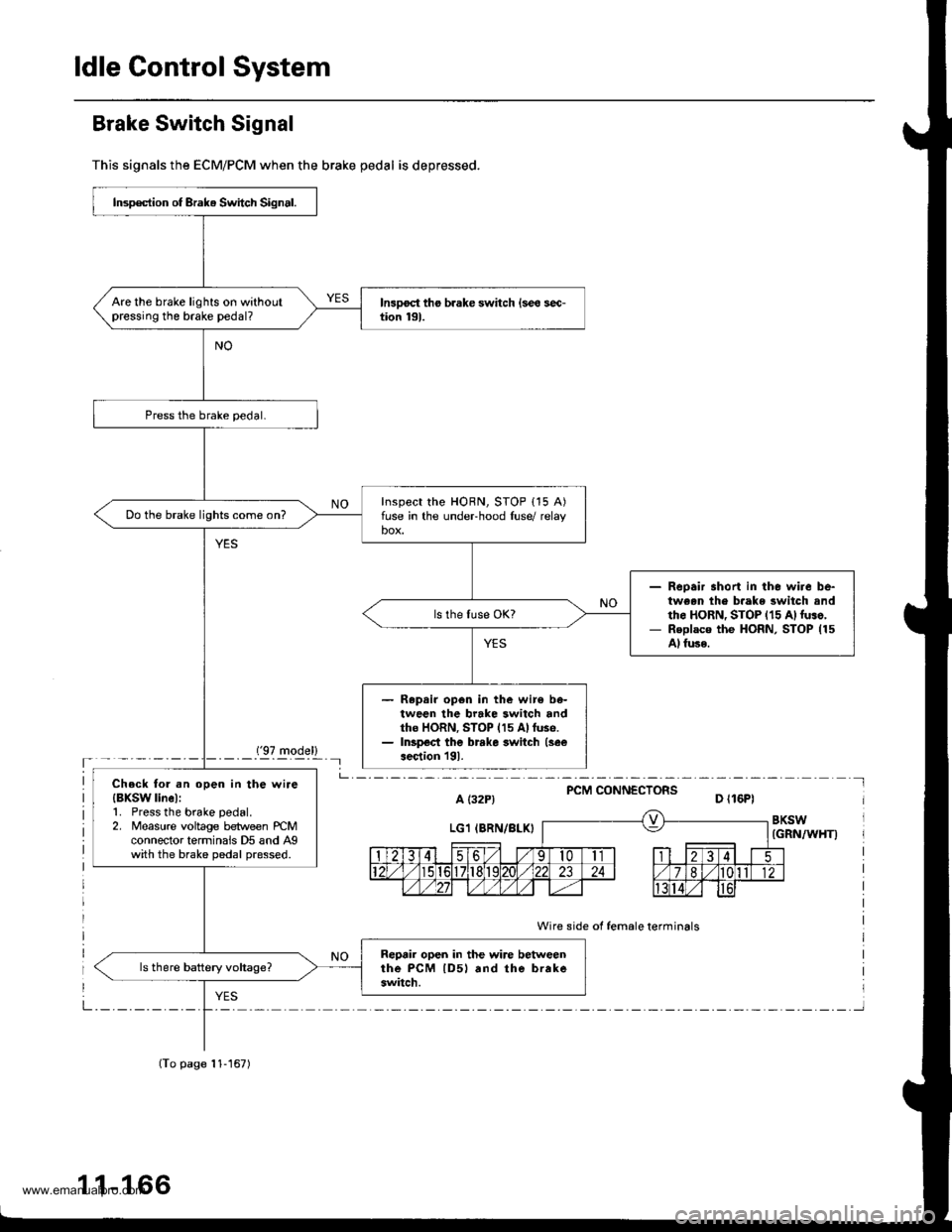
Brake Switch Signal
This signals the ECM/PCM when the brake pedal is depressed.
('97 model)'- - - - -_- Il
PCM CONNECTORSa t32P) D ll6Pl
BKSW(GRN/WHT)
Wire side of female terminals
Insp€ction of Brak. Switch Signal.
Are the brake lights on withoutpressing the brake pedal?
Inspect the HORN, STOP {15 A)fuse in the undeFhood luse/ relaybox.Do the brake lights come on?
Reoair short in the wire be-tween th€ b.ake switch andth6 HoRN, STOP {15 A)luso,Replaco the HoRN, STOP (15
Al fuse.
Repair op6n in the wir€ be-tween the brake switch andtho HORN, STOP (15 Allus6.Inspect the brrke switch (see
aection l9l.
Check tol .n open in the wire{BXSW linel:1. Press the brake pedal.2. Measure voltage between rcMconnector terminais D5 and Agwith the brake pedal pressed.
Reprir open in the wire betweenthe PcM lD5l rnd the brakeswitch.
(To page 11-167)
1 1-166
www.emanualpro.com
Page 369 of 1395
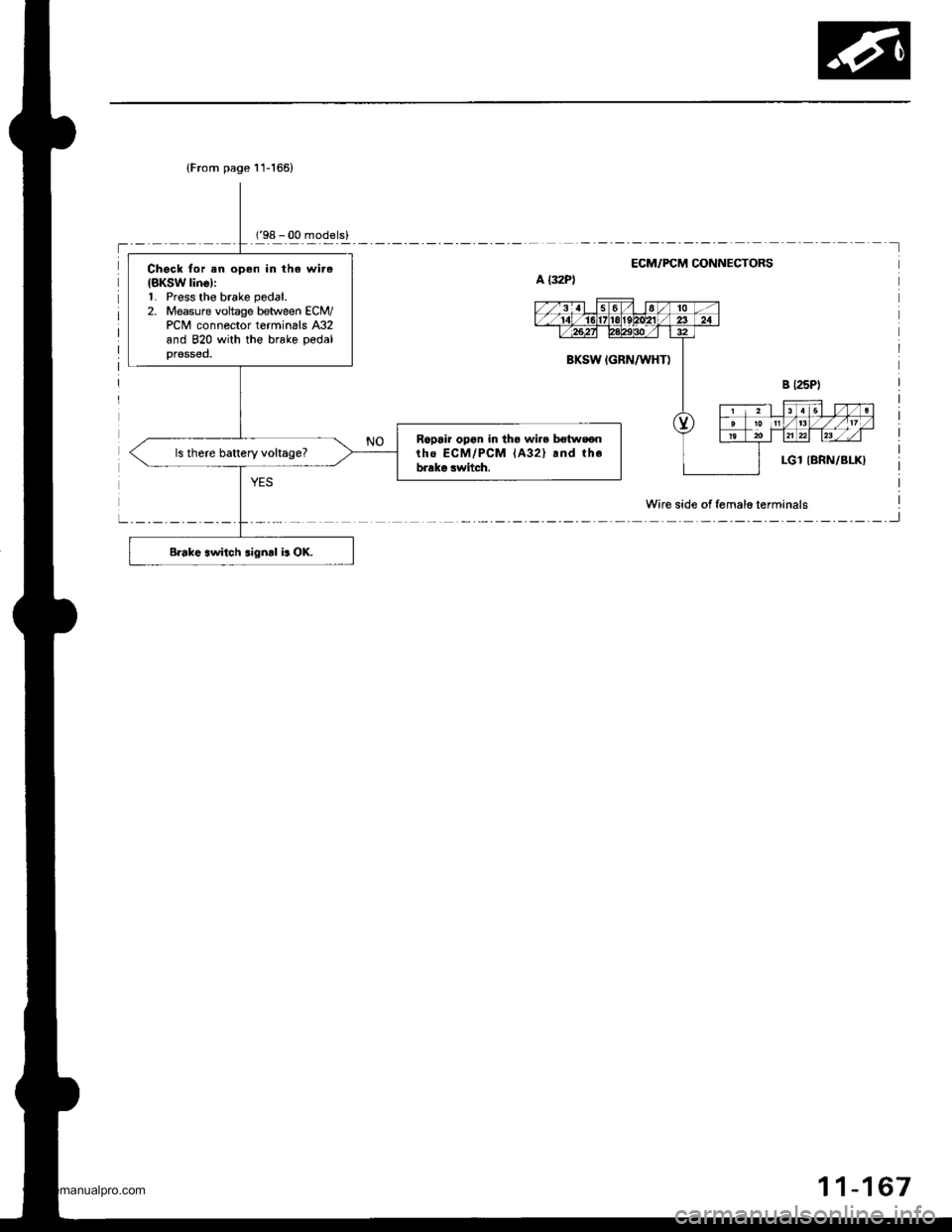
(From page 11-166)
Chock for en open in the wire(BKSW line):1. Press the brake pedal.
2. Measure vohage between ECM/PCM connector terminals A32and 820 with the brake pedalpressed.
Ropair opon in tha wire bstwsonrhe ECM/PCM lA32l rnd thebrako switch.
Brake switch signd b OK.
ECM/FCM OONNECTORS
Wire side of femalo terminals
11-167
www.emanualpro.com
Page 432 of 1395
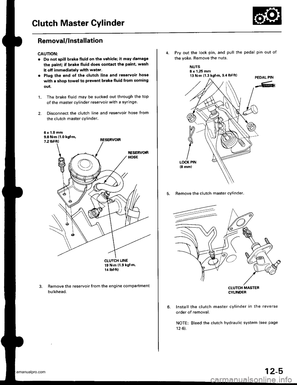
Glutch Master Cylinder
Removal/lnstallation
CAUTION:
. Do not spill brake fluid on the vehicle; it may damage
the paint; if brake tluid does contact the paint. wash
it off immediately with water.
. Plug the end ol the clutch line and leservoir hose
with a shop towel to prevent brake tluid trom coming
out.
The brake fluid may be sucked out through the top
of the master cylinder reservoir with a syringe.
Disconnect the clutch line and reservoir hose from
the clutch master cylinder,
't.
9.8 N.m 11.0 kst m,7.2 tbf.ftl
CLUTCH LINE
19 N'm 11 9 kgJ m'
14 lbf.frl
Remove the reservoir from the engine compartment
bulkhead.
13 N.m t1.3 kgt.m,g.il lbtft)
4. Prv out the lock pin, and pull the pedal pin out of
the voke. Remove the nuts.
NUTSI x 1.25 mm
5, Remove the clutch master cylinder.
CLUTCH MASTERCYLINDEF
Install the clutch master cylinder in the reverse
order of removal.
NOTE: Bleed the clutch hydraulic system {see page
12-61.
12-5
www.emanualpro.com
Page 433 of 1395
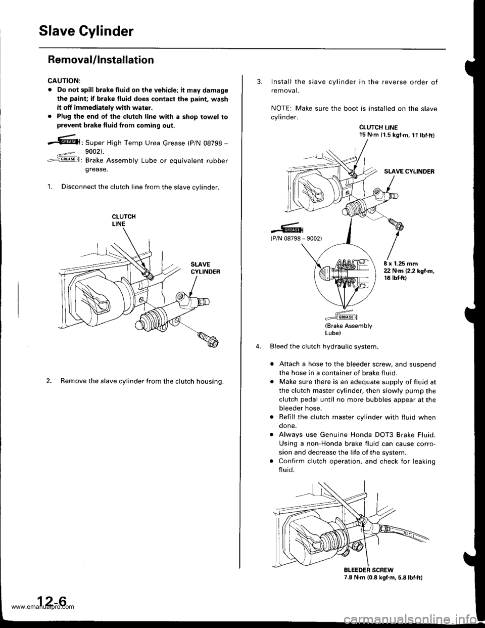
Slave Cylinder
RemovaUlnstallation
CAUTION:
. Do nol spill brake tluid on the vehicle; itmaydamage
the paint; if brake fluid do€s contast the paint, wash
it off immediately with water.. Plug the end of the clutch line with a shop towel toprevcnt brake tluid from coming out.
.6|l,Super High Temp Urea crease (p/N 08798 -
9002).
: Brake Assembly Lube or equivalent rubber
grease.
1. Disconnect the clutch line from the slave cvlinder.
2. Remove the slave cylinder from the clutch housing.
12-6
3. Install the slave cylinder in the reverse order ot
removal.
NOTEr Make sure the boot is installed on the slave
cylinder.
CLUTCH LINE15 N.m (i.S kgf.m, lt tbf.ftl
SLAVE CYLINDER
.-lG(P/N 08798 - 90021
E x 1.25 mm22 N.m (2.2 kgt.m,16 tbtft)
(Brake AssemblyLube)
Bleed the clutch hydraulic system.
Attach a hose to the bleeder screw, and suspend
the hose in a container of brake fluid.
Make sure there is an adequate supply of fluid at
the clutch master cylinder, then slowly pump the
clutch pedal until no more bubbles appear at the
bleeder hose.
Refill the clutch master cylinder with fluid whenqone.
Always use Genuine Honda DOT3 Brake Fluid.
Using a non Honda brake fluid can cause corro-
sion and decrease the life of the system.
Confirm clutch operation, and check for leaking
fluid.
7.8 N.m (0.8 kgf.m. 5.8 lbt.ft)BLEEDER SCREW
www.emanualpro.com