HONDA CR-V 1997 RD1-RD3 / 1.G Workshop Manual
CR-V 1997 RD1-RD3 / 1.G
HONDA
HONDA
https://www.carmanualsonline.info/img/13/5778/w960_5778-0.png
HONDA CR-V 1997 RD1-RD3 / 1.G Workshop Manual
Page 148 of 1395
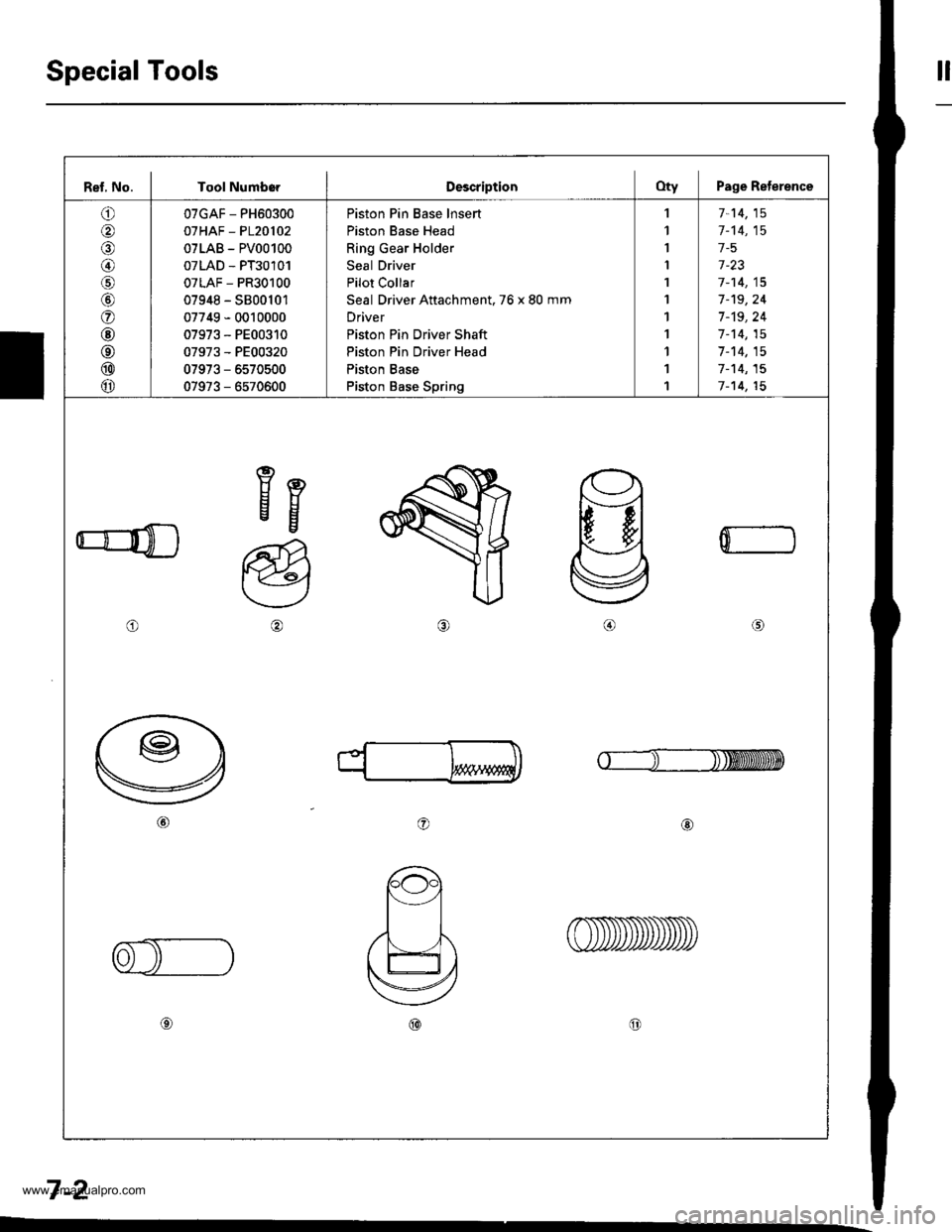
Special Toolstl
Ref, No. I Tool NumborDescriptionOty Page Reterence
o
@
@/6
@
o
@
@
@
@
07GAF - PH60300
07HAF - P120102
07LAB - PV00100
07LAD - PT30101
07LAF - PR30100
07948 - S800101
07749 - 0010000
07973 - PE00310
07973 - PE00320
07973 - 6570500
07973 - 6570600
Piston Pin Base lnsert
Piston Base Head
Ring Gear Holder
Seal Driver
Pilot Collar
Seal Driver Attachment. 76 x 80 mm
Driver
Piston Pin Driver Shaft
Piston Pin Driver Head
Piston Base
Piston Base Spring
,l
1
I
I
1
1
1
1
1
1
1
7-14,15
1-'t4,15
1-5
1-23
7-14,15
7-'t9,24
7 -'t9, 24
1-14,15
7-14,15
7-'t4,15
7-14,15
eEEg
o
a@
0
o@
7-2
www.emanualpro.com
Page 160 of 1395
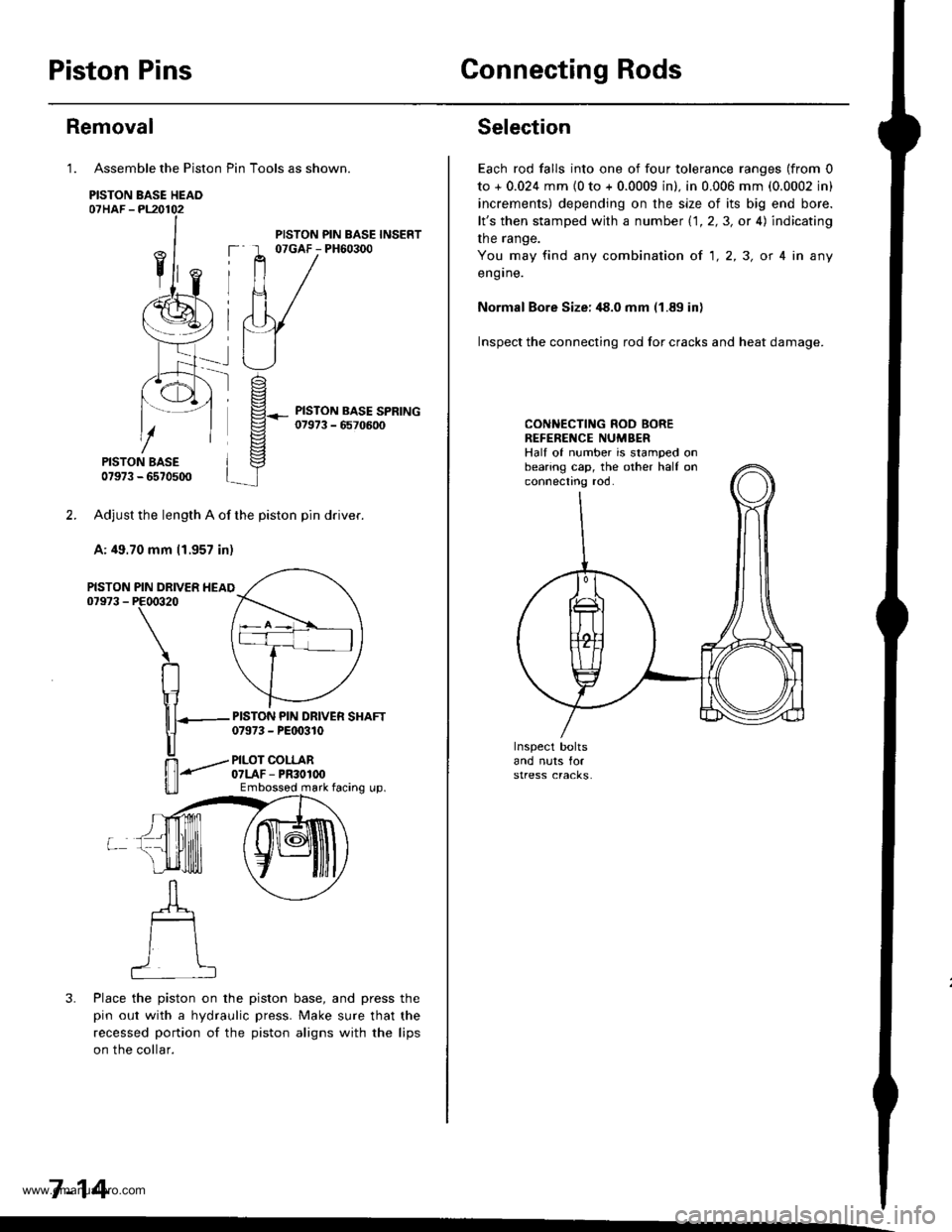
Piston PinsConnecting Rods
Assemble the Piston Pin Tools as shown.
PISTON BASE HEAO07HAF -PL20102
PISTON BASE07973 - 6570500
Adjust the length A of the piston pin dflver.
A: 49.70 mm 11.957 in)
PIN DRIVER HEAIPE00320
\
RIr1
nT---
u
ffi-"""-
u_ll
3. Place the piston on the piston base, and press the
pin out with a hydraulic press. Make sure that the
recessed portion of the piston aligns with the lips
on the collar.
7-14
Removal
1.
PISTON07973 -
PISTON PIN BASE INSERT07GAF - PH60300
PISTON PIN DRIVER SHAFT07973 - PEt 0310
PILOT COLLAR07LAF - PR30100Embossod mark facing up.
Selection
Each rod falls into one of four tolerance ranges (from 0
to + 0.024 mm {0 to + 0.0009 in). in 0.006 mm (0.0002 in)
increments) depending on the size of its big end bore.
lt's then stamped with a number 1.1.2,3, or 4) indicating
the range.
You may find any combination ot 1,2,3, or 4 in any
engrne.
Normal Bore Size: ,18.0 mm (1.89 in)
Inspect the connecting rod for cracks and heat damage.
CONNECTING ROD BOREREFENENCE NUMBERHalf of number is stamped onbearing cap, the other half onconnectno roo.
www.emanualpro.com
Page 792 of 1395
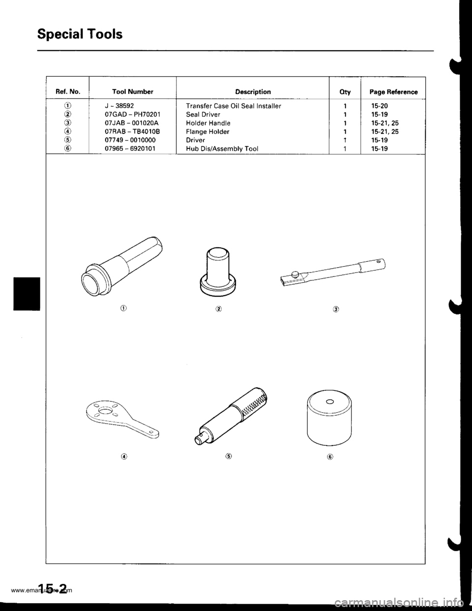
Special Tools
Ret. No.Tool NumberOescriptionotvPage Reler€nce
o
@aa
@/il
tol
J - 38592
07GAD - PH7020'1
07JAB - 0010204
OTRAB _TB40lOB
07749 - 0010000
07965 - 6920101
Transfer Case Oil Seal lnstaller
Seal Driver
Holder Handle
Flange Holder
Driver
Hub Dis/Assembly Tool
1
1
1
1
1
1
15-20
15-19
tc-zt, z9
15-21,25
15-19
15-19
6\
@
15-2
www.emanualpro.com
Page 809 of 1395
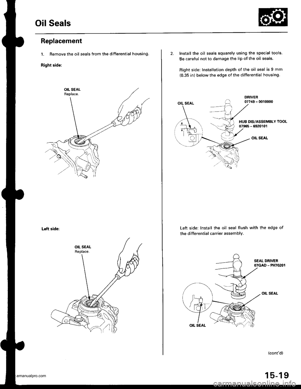
Oil Seals
Replacement
1. Remove the oil seals from the differential housing.
Right side:
Left side:
2. Install the oil seals squarely using the special tools.
Be carelul not to damage the lip ol the oil seals.
Right side: Installation depth of the oil seal is 9 mm
(0.35 in) below the edge of the differential housing.
OIL SEAL
OIL SEAL
Left side: Install the oil seal flush with the edge of
the differential carrier assembly.
OIL SEAL
HUB DIS/ASSEMBLY TOOL07965 - 6920101
(cont'd)
15-19
www.emanualpro.com
Page 1089 of 1395
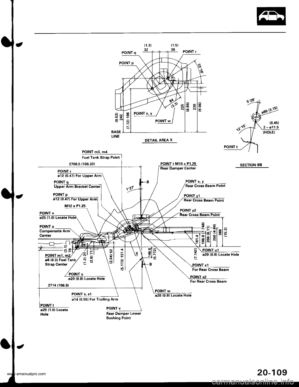
POlNTx.y / I
'sad
POINT m3, m4
Upper Arm
M12 x P1.25
Locate Hole
POINT 3, s1
o14 {0.551 For Trailing Aim
POINT v
Fuel Tank Strap Poinr
2700.5 (106.32)SECTION BBRear Damoer Center
POINT n
FOINT
rg (0.3) Fuel TStrap Center
271,1(10,6.9)
o2010.8| Locate Hole
For Rear Cros3 Beam
For Reer Cross Beam
POINT w
Bear Damper LowerBushing Point
I
\-
ql
ol
.df
20-109
www.emanualpro.com
